The article describes the design of a single-stage low-power tube UMZCH, used by the author in conjunction with speakers built on the basis of high-sensitivity broadband heads. The amplifier uses parallel connection of two 6P9 pentodes, characterized by high gain.
This made it possible to obtain an output power of up to 4 W when working with a signal source that provides a signal voltage of up to 1.5...2 V, i.e. from any CD player or smartphone.
The modern historical period, from a technology point of view, can be attributed to the digital era. Digital technologies in photography, sound recording, television, radio communications, navigation, in a “smart home”, etc. are the realities of our time. Along with computer communications and information transfer, they have provided opportunities that were previously unimaginable. In a certain sense, we can talk about the coverage of our entire life and production by this technology.
Recently, the number of lovers of good sound has begun to increase due to the generation born in the digital era and who have not seen either vinyl discs or tape recorders.
This is largely facilitated by the fact that modern people listen to most music through headphones from a multimedia player or smartphone, and in stationary conditions - through a simple speaker system of a TV or computer with simple single-chip UMZCH.
Nevertheless, with a claim to better sound reproduction, the well-known manufacturer of computer hardware, the Taiwanese company AOrep, in 2002 released the AX4B-533 Tube motherboard with a tube-based audio path and several “audiophile” MultiCap capacitors. Vishay resistors and Cardas wires. Moreover, the lamp was supplied by our Russian Sovtek 6922 (6N23P).
Then there was the AOrep AX4GE Tube-G design [1], with a three-tube preamplifier and simpler parts. And that’s all - this initiative was not taken up.
In fact, in order to radically influence sound reproduction, it is not enough to use only a buffer tube stage, and solving the problems of thermal conditions and lamp power supply immediately increases the cost of the product.
What can be done in this direction? The answer is to use a full-fledged tube amplifier. What requirements must the UMZCH meet? Of course, the amplifier must be built in accordance with certain rules that have developed as a result of centuries of practice in tube sound reproduction, taking into account modern technologies.
If possible, it should be uncomplicated, have sufficient power output and good parameters, reasonable dimensions and weight. The issue of thermal conditions and energy consumption may also be relevant. In general, a clear set of requirements, often in conflict with each other.
Unlike transistor circuitry, tube circuitry is traditional. It's difficult to come up with something breakthrough. The first thought when looking at the circuit diagram of a tube UMZCH is how simple it is!
But the secret of good sound, as a rule, is not in some unusual circuit design, but in careful design and the correct choice of elements used.
One of the principles of tube circuitry is that the audio path should be as short as possible, and the number of amplification stages should be minimal.
Although in practice not everything is so simple, nevertheless, all other things being equal, two amplification stages are preferable to three. Low cascade is one of the advantages of tube circuitry.
A large gain can be obtained from a tube stage, while the number of amplification stages is minimal. Hence the special sound panorama: musical instruments and voices are located throughout the acoustic space.
When listening to speakers with the “correct” tube amplifier, after a while you simply forget about the speakers, it’s as if they are not there, the sound dissolves in space, the brain stops associating them with the sound source (of course, with the appropriate recording quality of the original phonogram).
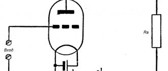
So, two cascades are better than three. Then one is better than two? But can an UMZCH have one amplification stage? In the middle of the last century, there were devices in which the UMZCH was built on just one lamp - the 6P9 pentode, for example, in the Record-12 and Yenisei TVs. It was also used in amateur amplifier designs.
Initially, this lamp was intended for the output stages of broadband amplifiers, in particular, in video amplifiers of television devices [2]. Nevertheless, lovers of tube sound successfully use this tube in the audio path in the pre-final and output stages. In addition, the lamp is still available and inexpensive.
The 6P9 pentode has an eight-pin (octal) base and a metal shock-resistant housing. Foreign analogues are 6L10 and 6AG7. In terms of the main parameters (but, alas, not in sound) the domestic finger lamp 6P15P is close to the 6P9 (and the power dissipation at the anode is up to 12 W).
Thanks to its high slope (10... 11 mA/V) and high internal resistance (80... 100 kOhm), the 6P9 pentode has a gain sufficient to build a single-stage power amplifier!
From one lamp with an input voltage of 1.5 Veff, you can get an output power of up to 2 W with a harmonic distortion of about 4%. But the problem is that the anode load should be approximately 10 kOhm. Making an output transformer for such an application is not an easy task.
But if you use two lamps connected in parallel, the sensitivity of the amplifier will not change, but the equivalent load resistance will be halved. The output power is, of course, twice as much.
It is already easier to make an output transformer for an equivalent load with a resistance of 5 kOhm. Apparently, the author of the design [3] reasoned in a similar way; The amplifier circuit shown there was taken as a basis.
Amplifier circuit
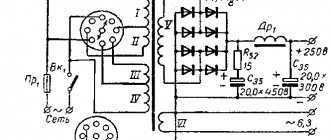
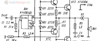
The diagram of one channel of a stereo amplifier with a power supply is shown in Fig. 1. This is a single-ended power amplifier with two pentodes connected in parallel, without feedback, with a fixed bias, providing an anode current of each lamp of 30 mA. You can also use automatic offset.
To do this, a resistor with a resistance of 68 ... 100 Ohms (selected for each lamp according to the anode current) with a power of 0.5 W should be included in the cathode circuit of each lamp, shunted by an oxide capacitor with a capacity of 500 ... 1000 μF for a rated voltage of 16 V.
The sound largely depends on the quality of this capacitor. In this case, the third grid is connected to the cathode, and the lower output of the VD7 zener diode according to the diagram must also be connected there.
The 6P9 pentode at the UMZCH output is a definite challenge to modern ideas, according to which it is believed that good sound can be obtained by using only triodes or pentodes and tetrodes in a triode connection.
Indeed, the triode is more linear and its internal resistance is lower (correspondingly, the inductance of the primary winding of the output transformer is lower).
But the maximum output power of such an amplifier on the 6P9 is reduced, and the sensitivity also decreases. On the other hand, there are many supporters of pentode amplifiers who claim that musical works of certain genres sound better with pentode amplifiers.
In addition, the main advantage of the described amplifier is that it is single-stage, and switching the lamps to triode mode will require a second amplification stage. And it’s difficult to say for sure what will sound better: a two- or three-stage UMZCH on a triode or a single-stage on a pentode [4].
It should be noted that when connecting lamps in parallel, their selection is required. After all, in such an amplifier the lamps work as if in a “duet”. And the result largely depends on how well they are selected; it’s not difficult to do this yourself, having the opportunity to choose them: 6P9 is not an expensive lamp.
The main difference between the amplifier circuit in Fig. 1 from that given in (3] is the presence of a voltage stabilizer for the second (screening) grid. Control listening showed that the introduction of a stabilizer noticeably improved the sound.
The fact is that the linearity of the pentode very much depends on the stability of the voltage on the second grid, and at large signal amplitudes the voltage on the second grid also begins to change. The filter capacitor between the grid and the common wire does not always cope with this phenomenon (at the lowest frequencies).
Rice. 1. Schematic diagram of a tube amplifier using 6P9 tubes.
This design uses a parametric stabilizer on six KS524G zener diodes and one KS512A for a total voltage of 150 V. The zener diode circuit is shunted by MBGO capacitors with a capacity of 4 μF and an oxide capacitor with a capacity of 100 μF for 160 V (Jamicon).
Instead of a zener diode circuit, you can use one KS650A. In this case, for two channels it is necessary to select two with the required stabilization voltage and install them on heat sinks (power dissipation - 1.5...2 W).
A stable voltage for the second grid can also be provided with a tube (on SPZP) or transistor stabilizer. Resistors R3, R4 in the anode circuits serve to control the anode current during setup. The voltage drop across them in millivolts is numerically equal to the anode current in milliamps. Once established, they can be eliminated.
Power switch SA1 is connected in series with the mains winding of the transformer. To increase the service life of the lamps, in order to protect them from the supply of anode voltage in an unheated state, another switch SA2 is installed directly in the anode voltage circuit.
Maximum permissible electrical values
| Highest filament voltage, V | 7 |
| Lowest filament voltage, V | 5.7 |
| Highest voltage at the anode, V | 330 |
| Highest voltage on the second grid, V | 330 |
| Maximum power dissipated at the anode, W | 9 |
| Maximum power dissipated on the second grid, W | 1.5 |
| The highest constant voltage between the cathode and the heater, V | 100 |
| Maximum leakage current between cathode and heater, μA | 40 |
| Maximum leakage resistance in the first grid circuit at a fixed bias, kOhm | 250 |
| The same, with automatic bias, MOhm | 1 |
Parts and components
Typically, to prevent possible excitations at high frequencies, the input signal is supplied to the control grids through “anti-ringing” resistors with a resistance of 1...3 kOhm. In this design, preference is given to the use of chokes in the grid circuit.
Comparative listening of the amplifier with BLP resistors, and then with DM2.4-20 chokes with an inductance of 20 μH in grid circuits revealed some advantage of the chokes. Similar chokes can be wound independently on ferrite rings, the number of turns is approximately 10-15.
Instead of a choke, you can use ferrite tubes with a diameter of 3 mm, which are placed on the signal wire going to the lamp. They can be found on old computer boards or switching power supplies. Such a tube can increase the inductance of a conductor (for example, an enameled winding wire) to 10...20 μH.
This design uses an imported variable resistor R1 (paired). It is better to install a dual variable resistor ALPS RK27 stereo (Blue Velvet) from the Japanese company ALPS Electric.
Fixed resistors can be used from any of the S2-23, S2-29, BC, BLP series. If you plan to use exclusively a computer as a signal source for this amplifier, then in this case you can do without a volume control at the amplifier input altogether, adjusting the input signal level directly from the computer, implementing the so-called “short path”.
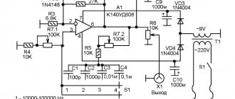
A special feature of the amplifier is the absence of interstage coupling capacitors. Here there is only a capacitor in the input circuit - polyethylene terephthalate K73-17. This design uses homemade output transformers (Fig. 2) on an armored tape magnetic core made of E310 steel, corresponding to the standard size ShL20x32, cross-sectional area - 6.4 cmg.
Rice. 2. Homemade output transformers.
It is closest to the industrially produced OSM 1-0.063 transformer. A winding wire with a diameter of 0.23 mm was used for the primary winding, and 1 mm for the secondary winding. For the operating mode indicated in the diagram, the load resistance reduced to the primary winding is slightly more than 4.8 kOhm.
The inductance of the primary winding for the calculated cutoff frequency fH = 40 Hz should be 19...20 H, which corresponds to approximately 5000 turns. Transformation coefficient l = 31 for a load with a resistance of 4 ohms and n = 22 for 8 ohms. In one layer of coil, up to 180 turns of the primary winding and up to 40 turns of the secondary winding can be laid.
Thus, 5040 turns of the primary winding can be wound in 22 layers, and 160 turns of the secondary (for a 4 Ohm load) can be wound in four layers. By adding another 69 turns to it, the transformer can be used for an 8 Ohm load. Considering that the additional winding is designed for a load of 8 ohms, it can be wound with a thinner wire.
To obtain sufficient bandwidth of the amplifier, the windings of the output transformer must be optimally sectioned.
Sectioning reduces the leakage inductance of the transformer, but excessive sectioning leads to an increase in interwinding capacitance, as well as limiting the bandwidth in the high frequency region.
Capacitance can be reduced by increasing the thickness of the interwinding insulation, but this reduces the fill factor and flux linkage between the windings.
The triode has low internal resistance; for him, the main problem is leakage inductance, so the primary winding of the triode is divided into 4-5 (or even more) sections, between which sections of the secondary winding are laid, which are usually connected in parallel.
The internal resistance of the pentode is high, the influence of leakage inductance is negligible. The main problem for it is the interwinding capacitance, so excessive sectioning, on the contrary, can limit the bandwidth. Unlike triode amplifiers, the transformers of pentode amplifiers are not subject to significant sectioning.
In many pentode amplifiers from the middle of the last century, the secondary winding was simply laid between the halves of the primary winding. For the same reason, if the anode voltage of the output lamp does not exceed several hundred volts, it is better to use paper as interwinding insulation rather than lavsan, fluoroplastic and other synthetic materials.
In this design, the following laying method is used: first, six layers of the primary winding are laid with 180 turns per layer (1080 turns), then two layers of the secondary winding (80 turns), then 11 layers of the primary winding (1980 turns), two more layers of the secondary and the remaining 11 layers of the primary winding. Then 69 turns were wound for a winding for a load of 8 ohms.
Not only the sections of the primary winding, but also the secondary winding are connected in series with each other. With this sectioning, it is more convenient to wind the secondary winding with pieces of wire of relatively short length.
In addition, the sections of the secondary winding cannot be made identical; the EMF induced in them is always slightly different. Connecting windings in series eliminates this problem.
Each subsequent section of the winding begins to be wound from the side where the previous one ended. Thus, the primary winding contains 5040 turns, the secondary winding contains 160 + 69 turns.
Winding is done turn to turn. Interlayer insulation is one layer of ordinary paper (for example, from a notebook), interwinding insulation is two or three layers. The insulation tapes should be 5 mm wider than the distance between the cheeks. Notches are made along their edges with scissors so that they fit between the cheeks without folds. This reliably isolates the layers and sections from each other.
To reduce the effect of direct current bias on the windings, the magnetic circuit of the transformer is assembled with a gap. For this purpose, paper inserts 0.1 mm thick are placed between its U-shaped parts.
Depending on the quality of the steel used in the transformer, the final thickness of the gasket can be selected at the final stage of setting up the amplifier to minimize distortion and maintain the signal level at the lowest frequencies, observed on the oscilloscope screen.
I-V characteristics in the triode Dynamic characteristics of the output power and Kg from the load resistance in the pentode connection This graph is given at anode voltage of 300V, second grid voltage of 150V, bias voltage of -3V, current of 30mA.
No, Mr. Elektrofil, you didn’t listen to 6P9 in a pentode with a high current and a small anode resistor. They wouldn't say so categorically. And 4P1L is inferior to it in this regard; a 6P9 driver in a pentode can only surpass 6P15P, especially if a high drive voltage is required. I also agree with 6S45P and that’s it (the latter requires a very high supply voltage). Believe me, when designing a single-ended amplifier based on double 6C4Cs, we tried all imaginable driver options - we wanted to get a two-stage amplifier. And the fours were driven into extreme modes, therefore, a large drive voltage was required, and a considerable current from the driver, and there would be distortion. appropriate. This problem was solved only by two types of DIM lamps
The voices of these drivers are completely different from each other. 6E5P plays bassistically, thoroughly, with soft, unobtrusive highs. 6Zh4, on the contrary, has excellent detail and resolution, but the bass is weaker and the dynamics and attack are softer. 6P9 combines to a certain extent the advantages of both 6Zh4 and 6E5P.
Listened to and averaged in many systems. Shalin
You, apparently, use 6P9 in a pentode connection, but I prefer a triode connection. In a triode, the gain of this lamp is 22–24, the slope is 11–12 mA/V. 6P15P, being an electrical analogue of 6P9, has a different electrode structure, and it sounds different: faster, sharper, less solid in the bass. In some systems this is a plus, in others it is a minus.
According to my observations, lamps in metal cylinders play better than their glass counterparts. For example, 6Zh4 beats 6Zh5P in a direct comparison. Alexei.
6P9 in a triode plays better than 6P15P - more articulated bass, cleaner highs.
In a pentode it can be used in almost the same modes as 6P15P.
But their electrode systems are completely different, this naturally affects the sound Shalin
I personally like the “voice” of the 6P9 in the pentode better than the “voice” of the 6P15P in the pentode. But that's just my personal preference. No more. LOki
Giblets 6P9 (Svetlana, ’73) “a fully-fledged third grid” is simply four L0ki traverses
For my 6P9 copies, I measured mu = 22 – 23, S = 12.7 – 14. Therefore, Ri is approximately 1.7 com.
The mode, if memory serves, was 200V, 50 mA, -4.5 V on the Shalin grid
Last night I listened to a new amp. At the input, I stupidly plugged the pentodes 6Zh8–6Zh4–6P9. Driver power supply 290V (shared with the output stage CLC filter 20μF - 12 H - 2500 μF with shunts), in the cathode 500 ohms with a 1000μF capacitor + film + mica, in the anode 30K, for 2 grids a 100k resistor + a 4μF capacitor with shunts... Modes 6Zh8–6Zh4 are close, only the latter has a smaller displacement and a higher gain. Both are good, but 6P9 leaves them no chance! Even without much warming up, the nine generally has a simply stupefying sound - super detailed, powerful and at the same time detailed low-frequency register, clarity and air in the shaft, in almost all recordings you can hear a kind of warm analog noise, which was previously less noticeable, but does not interfere at all. I didn’t even measure in what modes the 6P9 worked - I was so carried away by wiretapping, and the currents were even nonsense and the modes were far from optimal. We’ll have to play around with the modes, add 10 kilos in the anode... Yes, our luminaries were right when they talked about the excellent sound properties of the 6P9! Eduard Rusanov
High-linear mode for the 6P9 Cascade driver in pentode connection: Ua = 150 V; Uc2 = 150 V; Ia = 29 mA; Rн = 4.3 kOhm; Uc1 = -3 V; Upit = 278 V; Kg = 0.028% A. Nikitin
Dear Andrey! As it is written in textbooks, 6P9 is very critical in choosing a mode. I tried a lot of modes. At a very low Rн = 3.75 k and at a high Rн = 7.5 k, the sound is sharp with distortion, the current and Uc 2 are the same - 32 mA and 150 V. When Uc 2 is reduced to 125 V, the sound is softer and more pleasant to the ear. Now I have stopped (according to calculations) at the mode Rн = 5.6 k, 32 mA, Uc 2 140 V. Power supply 400v. Maybe I'm mistaken, but, unlike the modes recommended on the forum, Tsykin et al. recommend maximum modes to reduce distortion for pentodes. I selected a mode according to the current-voltage characteristics with a minimum Kg 3 = 2.1%, Kg 2 = 1% close to the curve of the maximum anode power approximately in the middle of the anode voltages. It turned out well. I don’t know what else you can get with 6P9. Mode Ua=230v, R=5.5k Uc 2=150v, Ia=40 mA, Upit=420v. This is based on the current-voltage characteristic. In reality, the power dropped to 417v. After warming up for 15 minutes, the mode was established: Ua=2225v, Uc 2= 140v, Ia=32 ma. There is no time yet to bring it to the design level. I’ll do it on the weekend. But it already sounds much better than the original one. Best regards, Mikhail Best regards, Mikhail 44
Mikhail, you can also turn on 6P9 with a triode - that will also be very good. I suspect even better than 6Zh4. But the gain will be half as much. Shalin
Practice has so far shown that the most harmonious (naturally, for me - all this is IMHO) mode was established at 8.2k in the anode (I haven’t tried less yet), 150 on the second grid, the cathode on the ground and a lithium battery in the grid. Anode about 192V. The second grid was powered by a separate small transformer. Initially, it was 9.1k in the anode, but then it was reduced to 8.2k. By ear - better! A few more auditory impressions. The battery in the grid was not impressive, I returned to 100 Ohms in the cathode (it was surprising myself, but my wife’s impressions were similar). The resistor in the cathode was nevertheless increased to 9.7k, because... There used to be a little annoying highs. I increased the cascade power supply, now at the anode 200V, on the grid the same 150V from a separate source. I’m listening to the difference between stabilizing the grid relative to the cathode and the ground... It’s still unclear. tried it. First of all, I started with the passport regime, i.e. 300V at the anode. There was some discomfort at the top, so I lowered it. In principle, I come to the option indicated in the post above, or rather almost to it. Oscillations occur between the modes Ua-k =192V, Uc 2 =150 and Ua-k=155, Uc 2=145. I indicate the voltages measured on the breadboard, so there is a difference of a couple of volts. The difference in sound is not very large, but still noticeable. I listened to the battery in both modes, but I still don’t like FEV
> Message from Mikhail 44
> In my experience, the less load the 6p9 has, the better it plays. It stopped at this current at 6.2 k.
I have about the same thing. On my own, I settled on 6.9 com. Started with 10 rooms. FAK
power unit
The power supply of the amplifier ultimately determines its power supply. A power supply transformer of sufficient power, a bridge semiconductor rectifier, chokes in the smoothing filter, filter capacitors - this is everything on which the sound quality directly depends.
The simplest option is to use a ready-made unified transformer. In this case, it turned out to be suitable and the anode-filament TAN43-220-50K was used. In addition to the mains winding, it contains four windings for a voltage of 56 V and a current of 150 mA, two windings for 12.6 V (current 150 mA) and two filament windings for 6.3 V (1.65 A).
To obtain the required anode voltage, the 56 V windings were connected in series (winding connections are shown in the diagram), and each filament winding powers a pair of lamps of the same channel.
One of the remaining windings is used as a source of negative bias to the control grids of the lamps. In addition to TAN43, TAN28, TAN29, TAN42 and any other network transformer with suitable winding voltages and an overall power of at least 60 W are also suitable.
Resistors R6-R9, traditionally connected in parallel with the filaments, form an artificial midpoint, reducing the background alternating current. An LED indicating that the amplifier is turned on is connected to one of the filament windings through a quenching resistor R13.
The anode rectifier uses MUR4100E diodes; you can also use any “fast” diodes for the appropriate voltage. Among the domestic ones, KD226V-KD226E are suitable.
In this case, it is useful to connect a 10 nF capacitor in parallel with each diode with a rated voltage of at least 400 V. Any rectifier diodes can be used in the bias rectifier.
Zener diode VD16 - any for stabilization voltage 5...6 V, for example KS156A.
Trimmer resistors R11, R12 - SP4-1 (SPO-0.15), very convenient multi-turn SP5-2, SP5-3 are suitable. Fixed resistors - MYAT, S2-23 or their analogues. It is advisable to use Jamicon or Samsung capacitors in the anode rectifier. Chokes L3, L4 in this design are equipped with ready-made imported ones for a current of 80 mA, a resistance of 180 Ohms, instead of which you can use chokes from old tube TVs, for example Dr5-0.08. Paired MTD-3 microswitches are used as switches.
Amplifier design
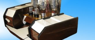
The amplifier is assembled on a U-shaped chassis with dimensions of 335x150x50 mm. Transformers and lamps are located on the upper part of the chassis, covered with a duralumin false panel. The network transformer is covered with a steel casing measuring 90x90x100 mm.
Rice. 3. Appearance of a tube amplifier.
Around the output transformers, in the corners, there are square racks, to which are attached duralumin plates covering the output transformers. The resulting box has external dimensions of 90x94x240 mm. The perimeter of the chassis is lined with a finishing laminated corner with external dimensions of 50x174x352 mm (Fig. 3).
The cladding - made of oak or birch planks, coated with varnish - will only add respectability to the product.
At the back of the case there are terminals for connecting cable wires to the speakers. On the front part of the chassis there is a volume control, anode and mains voltage switches, and an indicator LED. The front part is also covered with a duralumin false panel measuring 58x184 mm.
All metal surfaces are thermally powder coated. The inscriptions are laser engraved and blackened (Fig. 4).
Rice. 4. The inscriptions are applied using laser engraving.
The wiring and installation of the amplifier inside the chassis are shown in Fig. 5.
Rice. 5. Wiring and installation of the amplifier inside the chassis.
The assembly of the amplifier begins with the installation of lamp panels, network and output transformers, chokes, power supply boards and incandescent circuit wiring, which are carried out with thick (0.5 mmg cross-section) twisted wires.
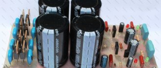
The filament circuits are located as far as possible from the input circuits of the amplifier. All parts of the power supply are mounted on three printed circuit boards (Fig. 6 - fig. 8.
Rice. 6. Power supply parts (board 1).
Rice. 7. Power supply parts (board 2).
Some of the small parts of the amplifier are mounted using hinged mounting. Some parts are soldered directly to the terminals of the lamp panels, and the main part is mounted on the petals of the circuit board.
Tinned copper wire is used as a common wire, installed on insulating posts between the circuit board and the lamp panels. The chassis is electrically connected to a common wire near the input connectors.
The circuits from the input connectors to the volume control and from the volume controls to the amplifier input are wired with a shielded wire of minimal length. Considering the level of the input signal, the input circuits can be routed using a regular twisted pair cable. In this case, the wires of the pair are used as signal and common.
Rice. 8. Power supply parts (board 3).
Setting up the amplifier
Setting up an amplifier involves installing and equalizing the quiescent current of the lamps. The anode current is monitored using a millivoltmeter, based on the voltage drop across resistors R3 and R4 (approximately 30 mV).
In this case, it is desirable to monitor the shape of the output signal using an oscilloscope at the load equivalent, at the low-frequency edge of the AF band and at a frequency of 1000 Hz, according to the maximum linearity of the output signal, especially at the maximum power of the amplifier, selecting more accurately the quiescent current by slightly changing the bias voltage using trimming resistors R11, R12.
The selection of lamps in pairs can be done directly in the amplifier. To do this, install all four lamps and set the bias voltage to -3 V on their control grids with resistors R11, R12 and fix their anode current. The lamps are rearranged so that their currents in pairs are closest.
Then, for one pair of lamps, the dependence of their anode current is determined, in the range of 10...50 mA in steps of 5...10 mA, on the bias voltage on their control grid. The results are recorded in tables (I* = f(Uc„)).
The resulting tables for all available lamps will allow you to more accurately select lamps in pairs within the operating range of their anode current. Naturally, all measurements must be carried out in the absence of an input signal. The lamps should first be warmed up for at least half an hour.
After selecting the lamps and finally setting their quiescent currents, it is possible to more accurately select the thickness of the non-magnetic gasket in the magnetic cores of the output transformers.
In this case, the optimal thickness of the gap is determined by visual inspection of the shape of the output signal on the oscilloscope screen as a compromise between the amplitude of the output signal and its shape at the low-frequency edge of the band.
It is impossible to give unambiguous recommendations here; it all depends on the quality of the transformer steel, the winding of the transformer, its shape and size. With a larger cross-section of the magnetic circuit, as a rule, it is possible to expand the range of amplified low frequencies.
Rated electrical data
| Filament voltage, V | 6.3 |
| Anode voltage, V | 300 |
| Voltage on the second grid, V | 150 |
| Bias voltage on the first grid, V | -3 |
| Filament current, mA | 650 +- 40 |
| Current in the anode circuit, mA | 30 +- 10 |
| Current in the second grid circuit, mA | 6.5 +- 2.5 |
| Characteristic slope, mA/V | 11.7 +- 2.5 |
| Output power at filament voltage 5.7 V, W | at least 2 |
| Internal resistance, kOhm | 130 |
| Nonlinear distortion factor, % | 7 |
About the measured parameters of the amplifier
The amplifier's parameters may seem modest by modern standards. The rated output power is 3 W, the maximum is 4 W (with an input voltage of 2 V), which is quite a bit by modern standards. But these are “tube” watts!
Due to a smooth, soft limitation of the amplitude of the output signal in lamps, compared to transistors. this power is equivalent to ten “transistor” watts, according to the subjective perception of sound. This phenomenon is well known to fans of tube sound. For comfortable listening to a tube amplifier in modern apartments with the “correct” speakers, as a rule, 1… 1.5 W is enough.
The operating frequency band at the -3 dB level is 20...20000 Hz. In Fig. Figure 9 shows the spectral composition of the output signal of one of the channels, with an output power of 1 W. In Fig.
10 - the same with an output power of 3 W. Harmonic distortion - THD in the English abbreviation, more precisely the coefficient of harmonic distortion, THD + N - the same plus amplifier noise, expressed as a percentage. The resulting distortion values (4%) are a good result for a tube amplifier.
Rice. 9. Spectral composition of the output signal of one of the channels, with an output power of 1 W.
Of course, modern transistor amplifiers have lower distortion, but their formal comparison, without taking into account the spectral composition of the signal, is meaningless.
Due to the peculiarities of push-pull circuits of modern transistor amplifiers, even harmonics are suppressed in them, which leads to a formal reduction in the value of the harmonic coefficient. But the predominance of odd harmonics, especially the third in the absence of the second, negatively affects the subjective perception of sound.
Experiments have shown that phonograms reproduced by amplifiers in the distortion spectrum of which harmonics smoothly fall off as their numbers are perceived more favorably by ear, but their spectrum should be short. Unlike transistor, this sound does not tire, enriching the sound of vocals and musical instruments.
Rice. 10. Spectral composition of the output signal of one of the channels, with an output power of 3 W.
Control listening to orchestral phonograms showed that the amplifier provides a good panorama of sound, each instrument is in its place, and their sound is localized not only in the horizontal plane, but also in depth and height. There is no connection of sound to the speakers. Of course, all this is only true if the recording quality is appropriate. All flaws in the phonogram immediately become noticeable.