A little history
The appearance of transistors in the middle of the 20th century seemed to lead to the complete displacement of the then dominant electronic tubes from radio technology.
One of the main disadvantages of radio tubes was their low efficiency. The heated cathode consumed significant energy and had a short service life. The electronic tube was criticized for the laboriousness of its manufacture; it was necessary to maintain the high-precision geometry of a large number of electrodes in the vacuum cylinder of the lamp.
The production of electronic equipment using lamps was gradually curtailed. In our country, the amount of equipment produced using radio tubes gradually decreased, but the factories for the production of tubes continued to operate. Oddly enough, this brought certain benefits to the domestic industry in the early 90s.
Music lovers played a major role in this. In the end, it turned out that audio amplifiers using vacuum tubes reproduce sound recordings better, more naturally, than those using semiconductor triodes.
Currently, the Hi-Fi equipment is filled with sound-reproducing equipment based on electronic tubes , mainly made in Russia.
From all this we can conclude that the design of radio equipment using vacuum tubes at the threshold of the beginning of the 21st century does not bring about a regression in radio electronics, but, on the contrary, allows us to take a new, more reasonable look at the field of application of vacuum tubes.
The operating principle of a radio-electronic lamp is based on the phenomenon of thermionic emission. The process of electrons escaping from the surface of solids or liquids is called electron emission.
Modern Applications
Air-cooled metal-ceramic generator triode GS-9B (USSR)
High frequency and high voltage power technology
- In high-power radio broadcast transmitters (from 100 W to several megawatts), powerful and ultra-powerful lamps with air or water anode cooling and high (more than 100 A) filament current are used in the output stages. Magnetrons, klystrons, so-called. Traveling wave radio tubes provide a combination of high frequencies, powers and reasonable cost (and often simply the fundamental possibility of existence) of the element base.
- The magnetron can be found not only in radar, but also in any microwave oven.
- If it is necessary to rectify or quickly switch several tens of kV, which cannot be accomplished with mechanical switches, it is necessary to use radio tubes. Thus, the kenotron provides acceptable dynamics at voltages up to a million volts.
Military industry
Due to the principle of operation, vacuum tubes are devices that are much more resistant to damaging factors such as electromagnetic pulses. A single device can contain several hundred lamps. In the USSR, for use in on-board military equipment in the 1950s, rod lamps were developed, which were distinguished by their small size and high mechanical strength.
Miniature lamp of the “acorn” type (pentode 6Zh1Zh, USSR, 1955).
Space technology
Radiation degradation of semiconductor materials and the presence of a natural vacuum in the interplanetary environment make the use of certain types of lamps a means of increasing the reliability and durability of spacecraft. The use of transistors in AMSLuna-3 was associated with great risk.
Increased environmental temperature and radiation
Tube equipment can be designed for a larger temperature and radiation range of conditions than semiconductor equipment.
Sound equipment
Tube sound
Electronic tubes are still used in audio engineering, both amateur and professional. The design of tube audio devices is one of the areas of the modern amateur radio movement.
Radio tube device
The design of a radio tube is ingeniously simple. The glass container contains metal electrodes arranged in a certain way, one of which is heated by electric current.
This electrode is called the cathode. The cathode is designed to create thermionic emission. In the lamp cylinder, under the influence of an electric field, electrons fly to another electrode - the anode.
The electron flow is controlled by other electrodes found in the lamp, called grids.
Operating principle
Vacuum vacuum tubes with heated cathode
- As a result of thermionic emission, electrons leave the cathode surface.
- Under the influence of the potential difference between the anode (+) and cathode (-), electrons reach the anode and form an anode current in the external circuit.
- With the help of additional electrodes (grids), the electron flow is controlled by applying an electric potential to these electrodes.
In vacuum tubes, the presence of gas degrades the tube's performance.
Gas-filled vacuum tubes
The main thing for this class of devices is the flow of ions and electrons in the gas filling the lamp. The flow can be created, as in vacuum devices, by thermionic emission, or it can be created by the formation of an electric discharge in the gas due to the electric field strength.
Microelectronic devices with field emission cathode
The process of miniaturization of electronic vacuum tubes led to the abandonment of heated cathodes and the transition to field emission from specially shaped cold cathodes made of specially selected materials. This makes it possible to bring device sizes down to micron sizes and use standard semiconductor industry technical processes in their manufacture. Currently, such structures are being actively researched.
Conventional graphic image of radio tubes
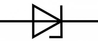
The simplest amplification tube is a triode . Its conventional graphic representation on radio-electronic circuits is presented in the form of a circle. Inside the circle, in its upper part, a vertical straight line is drawn with a perpendicular segment at the end, which symbolizes the anode; along the diameter of the circle, a grid is indicated in the form of strokes, and in the lower part, an arc with taps at the ends is a filament.
The bow above the filament indicates the cathode heater. Lamps with direct filament in their conventional graphic image do not have such a bow, for example, battery type 2K2P, as well as some other types of lamps. One lamp cylinder may contain a triode in combination with another type of lamp.
These are the so-called combination lamps. On the diagrams, next to the image of the lamp, its letter designation is placed (two Latin letters V and L) with a serial number according to the diagram (for example, VL1) and next to them the type of lamp used in the design (for example, VL1 6Н1П). A conventional graphic representation of various types of electronic tubes with letter designations is shown in Fig. 1.
In the figure, letters with numbers indicate: a - anode, C1 - control grid, k - cathode and n - filament. To generate, amplify and convert signals, currently used in amateur radio designs are mainly electronic tubes with an octal base, a finger series and a miniature series with flexible leads.
The last two types of lamps do not have a base; their leads are fused directly into the glass container. The cylinders of the listed series of lamps are mainly made of glass, but they are also made of metal (Fig. 2).
Rice. 1. Conventional graphic image and letter designation of electronic tubes of various types on radio-electronic circuits: a - triode; b, c - double triode; g - beam tetrode; d — setting indicator; e - pentode; g - heptode; h - double diode-triode; and - triode-pentode; k - triode-heptode; l - kenotron; m - double diode with separate indirectly heated cathodes.
Rice. 2. Options for the design of electronic tubes: a - glass cylinder, octal base; b — metal cylinder, octal base; c — glass cylinder with rigid leads (finger series); g - glass cylinder with flexible leads (baseless series).
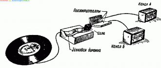
I. How a radio tube works
Getting acquainted with the history of the invention of the radio tube takes us back to 1881, when the famous inventor Thomas Edison discovered a phenomenon that later became the basis for the operation of almost every radio tube. While conducting experiments aimed at improving the first electric lamps, Edison introduced a metal plate inside the glass bulb of the lamp, placing it close to the heated carbon filament. This plate was not connected at all to the thread inside the flask (Fig. 1). The metal rod on which the plate was held passed through the glass to the outside. To prevent the filament from burning out, the air was pumped out of the lamp bulb. The inventor was quite surprised to notice the deviation of the needle of an electrical measuring instrument included in the conductor connecting the metal plate with the positive pole (plus) of the filament battery. Based on the concepts common at that time, one could not expect the appearance of current in the “plate - connecting wire - plus batteries” circuit, since this circuit was not closed. Nevertheless, current passed through the circuit. When the connecting wire was connected not to the plus, but to the minus of the battery, the current in the plate circuit stopped. Edison was unable to explain the phenomenon he discovered, which went down in the history of the radio tube under the name of the Edison effect.
An explanation for the Edison effect was given much later, after electrons, the smallest negative charges of electricity, were discovered in 1891 by Stoney and Thomson. In 1900 - 1903 Richardson undertook scientific research, the result of which was experimental and theoretical confirmation of Thomson's conclusion that the hot surface of conductors emits electrons. It turned out that the method of heating the conductor is indifferent: a nail heated on burning coals emits electrons (Fig. 2) in the same way as the filament of an electric lamp heated by electric current. The higher the temperature, the more intense the electron emission. Richardson deeply studied electron emission and proposed formulas for calculating the number of emitted electrons. He also found that, when heated to the same temperature, different conductors emit electrons to varying degrees, which was attributed to the structural properties of these conductors, i.e., the features of their internal structure. Cesium, sodium, thorium and some other metals have increased emissive properties. This was subsequently used in the design of intense electron emitters.
However, establishing the mere fact of the existence of electron emission from the surface of hot conductors (such emission is called thermionic or thermionic) does not yet explain the appearance of current in the circuit of the Edison lamp plate. But everything becomes completely clear if we remember two circumstances: 1) unlike electric charges tend to attract, and like ones tend to repel; 2) the flow of electrons forms an electric current of greater strength, the greater the number of electrons moving (Fig. 3). The plate connected to the positive of the lamp's incandescent battery is charged positively and therefore attracts electrons whose charge is negative. Thus, the apparent open circuit inside the lamp is closed and an electric current is established in the circuit, which passes through the electrical measuring device. The instrument needle deviates.
If the plate is charged negatively in relation to the filament (this is exactly what happens when it is connected to the minus of an incandescent battery), then it will repel electrons from itself. Although the hot filament will continue to emit electrons, they will not reach the plate. No current will arise in the plate circuit, and the arrow of the device will show zero (Fig. 4). The hot filament will be surrounded on all sides by a large number of electrons continuously emitted by the filament and returning to it again. This "electron cloud" around the filament creates a negative space charge, which prevents electrons from escaping from the filament. The space charge can be eliminated (“dissolve the electron cloud”) by the action of a positively charged plate. As the positive charge increases, the electron-attracting force of the plate increases, and more and more electrons leave the "cloud" towards the plate. The spatial negative charge around the thread decreases. The current in the plate circuit increases. The instrument needle deviates along the scale towards higher readings. Thus, the current in the plate circuit can be changed by changing the positive charge of the plate. This is the second possibility of increasing the current. We already know about the first possibility: the higher the temperature of the hot filament, the stronger the emission. However, the temperature of the filament can only be increased to certain limits, after which there is a danger of the filament burning out. But the increase in positive charge on the plate also has limits. The stronger this charge, the greater the speed of electrons flying towards the plate. This results in electronic bombardment of the record. Although the impact energy of each electron is small, there are many electrons, and the impacts can cause the plate to become very hot and even melt.
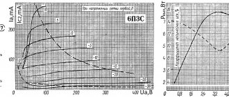
An increase in the positive charge of the plate is achieved by including a battery with a high voltage in its circuit, and the plus of the battery is connected to the plate, and the minus to the filament (to the positive pole of the incandescent battery, Fig. 5). By leaving the temperature of the filament unchanged, that is, maintaining the filament voltage unchanged, it is possible to determine the nature of the change in current in the plate circuit depending on the change in the voltage of the “plate” battery. This dependence is usually expressed graphically by constructing a line smoothly connecting the points corresponding to the instrument readings.
The horizontal axis from left to right usually shows increasing values of the positive voltage on the plate, and the vertical axis from bottom to top shows increasing values of the current in the plate circuit. The resulting graph (characteristic) indicates that the dependence of current on voltage is proportional only within limited limits. As the voltage across the plate increases, the current in its circuit increases, first slowly, then faster and then evenly (linear section of the graph). Finally, a moment comes when the increase in current stops. This is saturation: the current cannot increase: all the electrons emitted by the filament are completely used up. The "electronic cloud" has disappeared.
The lamp plate circuit has the property of one-way transmission of electric current. This one-sidedness is determined by the fact that electrons (“current carriers”) can pass in such a lamp only in one direction: from the hot filament to the plate. John Fleming, when he was conducting experiments on receiving wireless telegraph signals in 1904, needed a detector - a device with one-way current transmission. Fleming used an electron tube as a detector.
This is how the Edison effect was first practically applied in radio engineering. The technology was enriched with a new achievement - the “electric valve”. It is interesting to compare two circuits: the Fleming receiver circuit, published in 1905, and the modern circuit of a simple receiver with a crystal detector. These schemes are essentially not much different from one another. The role of the detector in Fleming’s circuit was performed by an “electric valve” (valve). It was this “valve” that was the first and simplest radio tube (Fig. 6). Since the “valve” passes current only when there is a positive voltage on the plate, and the electrodes connected to the positive current sources are called anodes, this is the name given to the plate, no matter what shape (cylindrical, prismatic, flat) it is given. The thread connected to the negative side of the anode battery ("plate battery" as we called it earlier) is called the cathode.
Fleming’s “valves” are still widely used today, but they go by different names. Every modern AC-powered radio contains a device that converts alternating current into the direct current required by the receiver. This conversion is carried out through "valves" called kenotrons. The design of the kenotron is, in principle, exactly the same as the device in which Edison first observed the phenomenon of thermionic emission: a flask from which air is pumped out, an anode and a cathode heated by electric current. The kenotron, passing current in only one direction, converts alternating current (i.e., a current that alternately changes the direction of its passage) into direct current, passing all the time in one direction. The process of converting alternating current into direct current by kenotrons is called rectification, which should apparently be explained by a formal feature: the alternating current graph usually has the shape of a wave (sinusoid), while the direct current graph is a straight line. It turns out that the wavy graph is “straightened” into a rectilinear one (Fig. 7). The complete device used for rectification is called a rectifier.
The general name for all radio tubes with two electrodes - an anode and a cathode (although the thread has two leads from the bulb, but represents one electrode) is a two-electrode lamp or - for short - a diode. Diodes are used not only in rectifiers, but also in radio receivers themselves, where they perform functions directly related to the reception of radio signals. Such a diode, in particular, is a 6X6 lamp, in which two diodes independent of each other are placed in a common bulb (such lamps are called double diodes or double diodes). Kenotrons often have not one, but two anodes, which is explained by the features of the rectifier circuit. The anodes are either located near a common cathode along the filament, or each anode surrounds a separate cathode. An example of a single-anode kenotron is a lamp of the VO-230 type, and two-anode ones are lamps 2-V-400, 5Ts4S, VO-188, etc. A graph expressing the dependence of the anode current of the diode on the voltage at the anode is called the diode characteristic.
In 1906, Lee de Forest placed a third electrode in the form of a wire mesh in the space between the cathode and anode. This is how a three-electrode lamp (triode) was created - the prototype of almost all modern radio lamps. The name “grid” has been retained for the third electrode to this day, although at present it does not always have the appearance of a grid. Inside the lamp, the grid is not connected to any other electrode. The conductor from the grid is brought out of the bulb to the outside. By connecting a grid battery between the output conductor of the grid and the terminal of the cathode (filament), you can charge the grid positively or negatively relative to the cathode, depending on the polarity of the battery.
When the positive pole (plus) of a grid battery is connected to the grid, and the negative pole (minus) to the cathode, the grid acquires a positive charge, and the greater the battery voltage, the greater the charge. When the battery is turned back on, the grid is charged negatively. If the grid conductor is directly connected to the cathode (with any terminal of the filament), then the grid acquires the same potential as the cathode (more precisely, what the point of the filament circuit to which the grid is connected has). We can assume that in this case the grid receives zero potential relative to the cathode, i.e. the grid charge is zero. Being under zero voltage, the grid has almost no effect on the flow of electrons rushing to the anode (Fig. 8). The bulk of them passes through the holes of the grid (the relationship between the sizes of electrons and the holes of the grid is approximately the same as between the sizes of a person and the distances between celestial bodies), but some of the electrons can still get onto the grid. From here, these electrons will travel through the conductor to the cathode, forming a grid current.
Having received a charge of one sign or another (plus or minus), the grid begins to actively interfere with the electronic processes inside the lamp. When the charge is negative, the grid tends to push away electrons that have a charge of the same sign. And since the grid is located on the path of electrons from the cathode to the anode, the grid will return electrons back to the cathode by repulsion (Fig. 9). If you gradually increase the negative charge of the grid, the repulsive effect will increase, as a result of which, with a constant positive
voltage at the anode and a constant filament voltage, the anode will receive fewer and fewer electrons. In other words, the anode current will decrease. At a certain value of negative charge on the grid, the anode current may even stop completely - all the electrons will be returned back to the cathode, despite the fact that the anode has a positive charge. The grid with its charge will overcome the action of the anode charge. And since the grid is closer to the cathode than the anode, its influence on the electron flow is much stronger. It is enough to change only a little voltage on the grid for the anode current to change very much. The same change in the anode current can, of course, be obtained by changing the anode voltage, leaving the voltage on the grid unchanged. However, to obtain exactly the same change in current in the anode circuit, a significant change in the anode voltage will be required. In modern triodes, a change in the grid voltage of one or two volts causes the same change in the anode current as a change in the anode voltage of tens or even hundreds of volts.
A positively charged grid does not repel, but attracts electrons, thereby accelerating their travel (Fig. 10). If you gradually increase the positive voltage on the grid, starting from zero, you can observe the following. At first, the grid will, as it were, help the anode: flying out of the hot cathode, the electrons will experience a stronger accelerating effect. The bulk of the electrons, heading towards the anode, will fly through the holes in the grid by inertia and end up in the “grid space” in the field of the amplified voltage of the anode. These electrons will go to the anode. But some of the electrons hit the grid directly and form a grid current. Then, as the positive charge of the grid increases, the grid current will increase, i.e., an increasing number of electrons from the total electron flow will be retained by the grid. But the anode current will also increase, as the electron speeds increase. Finally, all emission will be completely used up, the space charge around the cathode will be destroyed, and the anode current will stop increasing. Saturation will occur, the emitted electrons will be divided between the anode and the grid, with most of them falling on the anode. If you increase the positive voltage on the grid even more, this will lead to an increase in the grid current, but solely due to a decrease in the anode current: the grid will intercept an increasing number of electrons from the flow of them heading towards the anode.
At very high positive voltages on the grid (greater than the voltage at the anode), the grid current can even exceed the anode current; the grid can “intercept” all the electrons from the anode. The anode current will decrease to zero, and the grid current will increase to a maximum equal to the lamp saturation current. All electrons emitted by the filament land on the grid.
The characteristic properties of three-electrode lamps are clearly displayed by a graph of the dependence of the anode current on the grid voltage at a constant positive voltage at the anode. This graph is called the lamp characteristic (Fig. 11). At some negative voltage on the grid, the anode current completely stops; this moment is marked on the graph by merging the lower end of the characteristic with the horizontal axis along which the stress values on the grid are plotted. At this moment, the lamp is “locked”: all electrons are returned by the grid back to the cathode. The mesh overcomes the action of the anode. The anode current is zero.
When the negative charge of the grid decreases (movement along the horizontal axis to the right), the lamp “unlocks”: an anode current appears, weak at first, and then increasing more and more rapidly. The graph rushes upward, moving away from the horizontal axis. The moment when the grid charge is brought to zero is marked on the graph by the intersection of the characteristic with the vertical axis, along which the values of the anode current are plotted from zero upward. We begin to gradually increase the positive charge on the grid, as a result of which the anode current continues to increase and finally reaches a maximum value (saturation current), at which the characteristic bends and then becomes almost horizontal. All electron emission is completely used. A further increase in the positive charge of the grid will only lead to a redistribution of the electron flow: an increasing number of electrons will be retained by the grid and, accordingly, fewer of them will fall to the anode.
Typically, radio tubes do not operate at such high positive voltages on the grid, and therefore the dotted section of the anode current characteristic can be ignored. Note the characteristic starting at the point where the axes intersect. This is a characteristic of the grid current. A negatively charged grid does not attract electrons, and the grid current is zero. As the positive voltage on the grid increases, the current in its circuit, as the graph shows, increases.
Until now, we have assumed a constant voltage at the anode. But when this voltage increases, the anode current increases, and when it decreases, it decreases. This leads to the need to remove and, therefore, draw not one characteristic, but several - one for each selected value of the anode voltage. This results in a family of characteristics (Fig. 12), in which the characteristics corresponding to higher anode voltages are located higher, to the left. Over most of its length, the characteristics are parallel. So, there are two possibilities to influence the magnitude of the anode current: by changing the voltage on the grid and by changing the voltage on the anode. The first possibility requires fewer changes, since the grid is closer to the cathode than the anode, and therefore changes in its potential have a much greater effect on the electron current. The numerical coefficient indicating how many times the influence of the grid under exactly the same conditions is greater than the influence of the anode is called the lamp gain. Let's assume that a 20-volt increase in the plate voltage has the same effect on the plate current as a mere 1-volt change in the grid voltage. This means that the design of this lamp is such that the influence of the grid on the anode current is 20 times stronger than the influence of the anode, i.e., the gain of the lamp is 20. Knowing the value of the gain, you can estimate the amplification properties of the lamp, determine how many times stronger oscillations of the electric current will occur in the anode circuit if relatively weak electrical oscillations are applied to the grid. Only the introduction of a grid into the lamp made it possible to create a device that amplifies electrical oscillatory currents: the diodes we discussed earlier do not have amplifying properties. The steepness (slope) of the characteristic is of significant importance when assessing the properties of a lamp. A lamp with a high transconductance is very sensitive to changes in grid voltage: it is enough to change the grid voltage to a very small extent for the anode current to change within significant limits: The transconductance is quantified by the change in the anode current in milliamps when the grid voltage changes by 1 volt.
The cathode in a radio tube is a thin metal wire (thread) heated by current. If such a filament is heated with a direct current, then the emission of electrons will be strictly constant. But almost all modern radio broadcast receivers are designed to be powered by alternating current, and the filament cannot be heated with such current, since the emission of electrons will change and “pulse.” An AC hum will be heard from the loudspeaker - an unpleasant hum that makes it difficult to listen to the program.
Of course, it would be possible to first rectify the alternating current using a diode and turn it into direct current, as is done to power the anode circuits - we have already talked about this. But a much simpler and more effective method has been found that allows direct alternating current to be used to heat the cathode. A tungsten filament - a heater - is placed in the channels of a thin and long porcelain cylinder. The thread is heated by alternating current and its heat is transferred to a porcelain cylinder and a nickel “case” placed over it (Fig. 13), on the outer surface of which a thin layer of alkali metal oxides (strontium, barium, cesium, etc.) is applied. These oxides are distinguished by their high emissivity even at relatively low temperatures (about 600 degrees). It is this layer of oxides that is the source of electrons, i.e. the cathode itself. The conclusion is
The cathode from the flask is connected to a nickel “case”, and there is no electrical connection between the cathode and the filament. The entire heated device has a relatively large mass, which does not have time to lose heat during rapid changes in alternating current. Thanks to this, the emission is strictly constant and no background is heard in the receiver. But the thermal inertia of the cathode of the lamps in the receiver is the reason that the switched on receiver does not start working immediately, but only when the cathodes heat up.
The grids in modern lamps most often have the form of wire spirals: “dense grid” - the turns of the spirals are located closer to each other, “sparse grid” - the distances between the turns are increased. The denser the grid, the greater, other things being equal, its influence on the flow of electrons, the greater the gain of the lamp.
In 1913, Langmuir increased the number of electrodes in the lamp to four, proposing to introduce another grid into the space between the cathode and the grid (Fig. 14). This is how the first tetrode was created - a four-electrode lamp with two grids, an anode and a cathode. The grid that Langmuir placed closer to the cathode is called the cathode grid, and the “old” grid was called the control grid, since the cathode grid plays only an auxiliary role. With its small positive voltage received from part of the anode battery, the cathode grid accelerates the flow of electrons to the anode (hence another name for the grid - accelerating), “resolving” the electron cloud around the cathode. This made it possible to use the lamp even at relatively low voltages at the anode. At one time, our industry produced a two-grid lamp of the MDS type (or ST-6), the passport of which stated: operating anode voltage 8-20 V. The most common Micro (PT-2) lamps at that time usually operated at much higher voltages - on the order of 100 V. However, lamps with cathode grids did not become widespread, since even more advanced lamps were soon proposed instead. In addition, the “dual grids” had a significant drawback: the positively charged cathode grid took a very large number of electrons from the total flow, which amounted to a waste of them. Although the opportunity to work with low anode voltages was attractive, this was countered by a large waste of current - there was no tangible benefit. But the introduction of the second grid served as a signal for radio tube designers: the “era” of multi-electrode tubes had begun.
In 1916, Schottky, while conducting experiments with triodes and pursuing the task of increasing their gain, found it necessary to introduce a second grid into the space between the anode and the existing (control) grid (Fig. 15). By applying a positive voltage to this - anode - grid, approximately equal in value to half the anode voltage, Schottky to a certain extent achieved the required. But a decade passed before these works received widespread recognition and application. In 1926, Hall structurally modified the anode grid, giving it the appearance of an electrostatic screen, with which he separated the anode from all other electrodes. Why was this needed? In a triode, the anode and the grid form a kind of small capacitor, the capacitance of which, however, is sufficient for the anode circuit to be electrostatically connected to the grid circuit.
The presence of this parasitic connection is a sufficient condition for turning the amplifier stage into a generator of electrical oscillations. Instead of amplifying the electrical oscillations supplied to it from the outside, the lamp will begin to create its own oscillations, and no normal amplification is obtained. A receiver with self-exciting cascades whistles, howls, distorts wildly and generally stops working. To overcome the possibility of self-excitation, it is necessary to eliminate the parasitic connection between the anode and grid circuits, that is, reduce the capacitance between the anode and the grid to a negligible value. The anode grid, made in the form of a screen, serves precisely this task. It “intercepts” the electrical power lines and thereby separates the anode from the grid.
Typically, the shielding mesh is designed in such a way that only that part of it that faces the anode is made in the form of a spiral-wound wire mesh. The rest of this electrode, for better shielding, is made solid, without holes. In order not to noticeably weaken the anode current, a positive voltage is applied to the shielding grid (from the anode battery), equal in value to approximately half the anode voltage. Tubes with shielding grids differ favorably from triodes by their large gain: for triodes it usually does not exceed 20 - 100, and for shielded lamps it is measured in the hundreds, so instead of 2 triodes, you can use 1 shielded lamp.
I had to deal with one unpleasant phenomenon in shielded lamps. The fact is that electrons hitting the surface of the anode can knock out so-called secondary electrons from it. These are, by their nature, the same electrons, only released from the metal surface not by heating (as from the cathode), but by electron bombardment. One bombarding electron can knock out several secondary electrons. It turns out that the anode itself turns into a source of electrons (Fig. 16). Up close
There is a positively charged shielding grid located from the anode, and secondary electrons, escaping at low speeds, can be attracted to this grid if at any moment the voltage on the grid is greater than the voltage on the anode. This is exactly what happens when a shielded tube is used in the final low-frequency amplification stage. Rushing toward the shielding grid, the secondary electrons establish a reverse current in the lamp, and the operation of the lamp is completely disrupted. This unpleasant phenomenon is called the dynatron effect. But there is a way to combat this phenomenon. In 1929, the first lamps with five electrodes appeared, of which two were the anode and cathode, and the other three were grids. Based on the number of electrodes, these lamps are called pentodes. The third mesh is placed in the space between the shielding mesh and the anode, i.e. it is closest to the anode. It is connected directly to the cathode and therefore has the same potential as the cathode, i.e. negative with respect to the anode. Thanks to this, the grid returns secondary electrons back to the anode and thereby prevents the dynatron effect. Hence the name of this grid - protective or anti-dynatron. In many of their qualities, pentodes are superior to triodes. They are used to amplify high and low frequency voltages and work great in final stages.
The increase in the number of grids in the lamp did not stop at the pentode. The series "diode" - "triode" - "tetrode" - "pentode" was replenished with another representative of the tube family - the hexode. This is a lamp with six electrodes, four of which are grids (Fig. 17). It is used in high-frequency amplification and frequency conversion stages in superheterodyne receivers. Typically, the strength of radio signals arriving at the antenna, especially on short waves, varies within very significant limits. The signals either increase or quickly fade (fading phenomenon). The hexode is designed in such a way that it automatically quickly changes the gain: it amplifies weak signals to a greater extent, and strong signals to a lesser extent. As a result, audibility is leveled out and maintained at approximately the same level. Automaticity of action is achieved by changing the potentials on the grids in time with changes in the strength of the received signals. This hexode is called a fading hexode. In conventional receivers, such gain control also takes place, but is carried out using pentodes with an elongated lower part of the characteristic, where the slope has a smoothly varying value.
Such pentodes are called "varimu".
The second category of hexodes is mixing hexodes. In superheterodyne receivers, the received signal is first lowered in frequency and then amplified. This reduction or frequency conversion can also be accomplished using triodes, as was done previously. But mixing hexodes perform this function more efficiently. In our practice of broadcast reception, other lamps with even more grids are used to perform this function. These are pentagrids (five-grid lamps) or, as they are otherwise called, heptodes (seven-electrode lamps). Lamps of type 6A8 and 6L7 belong to this category of lamps. For frequency conversion in superheterodyne receivers it is used
also a six-grid lamp (eight electrodes) is an octode. Unlike a pentagrid, an octode is a combination of a triode and a pentode (while a pentagrid is a triode with a tetrode). Appearing later than the pentagrid, the octode is superior in quality to its predecessor.
But it is not only in the “grid direction” that lamps have developed in recent years. We have already talked about placing two “electric valves” in a common flask earlier, touching on the device of a double diode of the 6X6 type. Combinations such as diode-triode, double triodes, double diode-triodes (DDT), double diode-pentodes (DDP), triode-hexodes, etc. are now widely used. For the most part, such combination lamps have a common cathode. The work of one lamp is similar to the work of several simpler ones. For example, a 6N7 lamp is a double triode - two separate triodes in a common bulb, kind of twins. This lamp successfully replaces two triode lamps and can be used either in a two-stage resistor amplifier or in a push-pull circuit, for which it is actually intended. After detection, which is carried out in superheterodyne receivers, usually through diodes, amplification must be performed. For this purpose, an amplifying triode is now placed in a common flask with a detection diode; This is how diode-triodes appeared. In superheterodyne receivers, for automatic volume control (AVG), it is necessary to obtain a direct current, the value of which would change in time with the strength of the received signals. For these purposes, a separate diode could be used, but it turned out to be possible to place it in a diode-triode flask. So, three lamps were placed in one lamp: two diodes and a triode, and the lamp was called a double diode-triode. In the same way, the pentode diode, hexode triode, etc. arose.
The 6L6 type lamp stands somewhat apart from other lamps. This is a very interesting lamp: it does not have one electrode, but it is, as it were, implied. On the one hand, this lamp is an obvious tetrode, since it has only four electrodes: a cathode, an anode and two grids, one of which is control and the other is shielding. But, on the other hand, 6L6 is a pentode, because it has all its properties and very positive features. The role of the protective grid, mandatory for the pentode, in the 6L6 lamp is performed by ... empty space, an artificially created zone located between the anode and the shielding grid (Fig. 18).
A zero potential is created in this zone, exactly the same as what the protective grid would have if only it existed in this lamp. To create such a zone, design changes had to be made. In particular, the anode is located further from the protective grid. The “imaginary electrode” acts on secondary electrons in the same way as the protective grid and also prevents the occurrence of the dynatron effect. The electrons in this lamp go from the cathode to the anode as if in separate rays, passing in the spaces between the turns of the grids; hence the name of the lamp - beam. The turns of the grids are arranged in such a way that the shielding grid is in the “electronic shadow” created by the turns of the control grid closest to the cathode. Due to this, the shielding mesh attracts relatively few electrons to itself, and the emission current is almost completely spent on the anode circuit. On the side narrow sides of the cathode, the lamp has metal shields connected to the cathode, due to which electrons reach the anode only from certain sides where a uniform electric field is created. There are no “electronic swirls”, which is reflected in the absence of distortion in the operation of the lamp. Ray lamps have a high efficiency and are capable of delivering very high output power. Suffice it to say that two such lamps in a push-pull circuit, under certain conditions, can deliver up to 60 watts of useful power.
Lamps are being improved not only electrically, but also purely structurally. The first radio tubes were not much different in appearance from electric lamps and lit almost the same way. Many still remember the first radio tubes developed by our compatriots Prof. A. A. Chernyshev and prof. M. A. Bonch-Bruevich. In recent years, the appearance of the radio tube has changed a lot. Our domestic scientific thought made a great contribution to the creation of new types of lamps and improvement of previously produced ones. It is enough to point out the work of the team of the Stalin Prize laureate, order bearer prof. S. A. Vekshinsky. At first, the radio tube, to the great surprise of novice radio amateurs, stopped shining and was turned only to performing its direct duties. Then the configuration of the cylinder was repeatedly changed. Small-sized lamps appeared, a little more than half the size of a little finger. For laboratory-type radio equipment, lamps were made, the size and shape of which were similar to acorns. Currently, metal lamps are widespread, which are somehow inconvenient to call lamps, since they do not glow at all. Replacing a glass cylinder with a metal (steel) one is not an easy replacement: metal lamps compare favorably with glass lamps in their small dimensions (a 6X6 lamp, for example, is only the size of a walnut), durability, good electrical shielding (no need to put on bulky shields, as with glass lamps ), smaller interelectrode capacitances, etc. However, there are also disadvantages to metal lamps, the most significant of which is the strong heating of the metal bulb, especially in kenotrons.
Nowadays, many types of lamps are available in two versions: metal and glass. The use of a “key” on the lamp stem makes it easier to insert the lamp into the socket. If previously it was possible to carelessly touch the sockets of the socket with the wrong pins, as a result of which the lamp, flashing spectacularly for a moment, was permanently out of order due to the filament burning out, now it is impossible to insert the lamp until the pins are in the correct position. Errors leading to the destruction of the lamp are excluded.
Lamp technology is constantly being improved. Its level determines the progress of radio technology.
Electrical parameters of lamps
Modern high-quality audio amplifiers generally rely on three-electrode tubes called triodes. The general basic electrical parameters of receiving and amplifying tubes, which are usually given in reference books, are the following: gain μ, characteristic slope S and internal resistance Rj.
The so-called static characteristics of the lamp are important: anode-grid and anode characteristics, which are presented in graph form.
Having these two characteristics, you can graphically determine the three main parameters of lamps given above. For lamps for various purposes, special parameters characteristic of them are added to the listed characteristics.
Tubes used in audio amplifiers are also characterized by parameters that depend on one or another mode of operation of the output tube, in particular, output power and nonlinear distortion factor.
For high-frequency lamps, the characteristic parameters are :
- input capacitance,
- output capacity,
- passage capacity,
- broadband factor
- equivalent impedance of intra-lamp noise.
Moreover, the smaller the total value of the input and output interelectrode capacitances of the lamp and the greater the slope of its characteristic, the greater the gain it provides at higher frequencies.
The ratio of the slope of the lamp characteristic to its pass-through capacitance serves as an indicator of the stability of the amplification. Greater gain from a high-frequency lamp can be obtained at high frequencies, in the case when the total value of the input and output capacitances of the lamp is smaller and the slope of its characteristic is greater.
When choosing a tube for the first amplification stages, special attention should be paid to its equivalent resistance to intra-tube noise.
The operating efficiency of frequency-converting lamps is assessed by the conversion slope. The conversion slope is, as a rule, 3...4 times less than the slope of the lamp characteristic. Its value increases with increasing local oscillator voltage.
For kenotrons, the main parameter is the amplitude of the reverse voltage. The highest values of the reverse voltage amplitude are characteristic of high-voltage kenotrons.
Tube sound: fact or fiction?
Low frequency amplifiers or simply sound amplifiers are the most famous modern use of radio tubes, which also causes a lot of controversy.
It even goes as far as “holiwars” between adherents of tube and transistor sound. The tube sound is said to be more “soulful” and “soft” and pleasant to listen to. While transistor sound is “soulless” and “cold”.
To further better understand what is written here, we recommend reading the feature article about sounds and their effect on our brains.
Nothing happens for nothing, and it is unlikely that such disputes and opinions arose out of nowhere. At one time, scientists became interested in the question of whether tube sound is really more pleasant to the ear. Quite a lot of research has been done on the differences between a lamp and a transistor.
According to one of them, tube amplifiers add even harmonics to the signal, which are subjectively perceived by people as “warm,” “pleasant,” and “cozy.” True, there are so many people, so many opinions, which is why debates are still ongoing.
Arguing is often a waste of time. But the student service, on the contrary, will help save valuable man-hours. Contact our specialists for quality assistance in any field of knowledge.
Kenotrons and diodes
In Fig. 3 gives the main parameters, typical mode and pinout of some types of electronic tubes, widely used in radio-electronic designs at the present time and used in the past.
Rice. 3. Basic parameters, typical mode and pinouts of some types of widely used electronic tubes.
Rice. 3. Basic parameters, typical mode and pinouts of some types of widely used electronic tubes (continued).
Main types and classification
Small-sized (“finger”) radio tubes
Main types of electronic vacuum tubes:
- Diodes (easily made for high voltages, see kenotron)
- Triodes
- Tetrodes
- Pentodes
- Beam tetrodes and pentodes (as variations of these types)
- Hexodes
- Heptodes
- Octodes
- Nonodes
- Combination lamps (actually include 2 or more lamps in one cylinder)
- Lamps with secondary emission and special lamps with special characteristics (quadratic, hyperbolic) were created for analog computers, but were not widely used.
Rice. 4.1. Classification of vacuum electronics devices
Kenotrons and diodes
Conversion tubes and cathode ray tuning indicators
Rice. 3. Basic parameters, typical mode and pinouts of some types of widely used electronic tubes (continued)
Triodes
- S is the slope of the anode-grid characteristic;
- m is the gain;
- Rс is the highest resistance in the grid circuit;
- Svh - input capacitance of the lamp (grid cathode),
- Svyh - output capacitance of the lamp (cathode-anode),
- Spr—pass capacity of the lamp (grid-anode);
- Pa is the highest power dissipated by the anode of the lamp.
Rice. 3. Basic parameters, typical mode and pinouts of some types of widely used electronic tubes (continued).
Dual triodes
Rice. 3. Basic parameters, typical mode and pinouts of some types of widely used electronic tubes (continued).
Rice. 3. Basic parameters, typical mode and pinouts of some types of widely used electronic tubes (continued).
Tube intro
Lamps were previously widely used in circuit design; the first electronic devices were built using them. The golden age of radio tubes was in the first half of the 20th century. For our grandfathers and great-grandfathers, giant computers that occupied an entire room and basked like hell were much more familiar. You can't watch a TV series on a car like this.
Then there was a time when Soviet microcircuits became the largest in the world. But this is another story, which began after the advent of semiconductor devices. As you understand, this article is about the operation of a vacuum tube and its modern use.
Output pentodes
Rice. 3. Basic parameters, typical mode and pinouts of some types of widely used electronic tubes (continued).
Rice. 3. Basic parameters, typical mode and pinouts of some types of widely used electronic tubes (end).
Literature: V.M. Pestrikov. Encyclopedia of amateur radio.
Vacuum devices
Vacuum is the absence of matter. More precisely, its almost complete absence. In physics, there are high, medium and low vacuums. It is clear that there cannot be an electric current in a vacuum, since current is the directed movement (particles) of charge carriers, which in a vacuum have nowhere to come from.
But out of nowhere? Metals release electrons when heated. This is the so-called thermionic emission. The operation of electronic vacuum devices is based on it.
Thermionic emission was discovered by Thomas Edison. More precisely, the scientist found out that when the filament is heated and there is a second electrode in the vacuum flask, the vacuum conducts current. At that time, Edison did not fully appreciate the significance of his discovery, but just in case, he patented it. Conclusion: in any unclear situation, patent it!
Vacuum devices are hermetically sealed cylinders with electrodes inside. Cylinders are made of glass, metal or ceramics, after the air has been pumped out of them.
In addition to vacuum tubes, there are the following vacuum devices:
- microwave devices, magnetrons, klystrons;
- kinescopes, cathode ray tubes;
- X-ray tubes.