The 78L05 low-power positive polarity stabilizer is designed for use in DC power supplies. In addition, it can be used with power elements to make voltage regulators.
They have built-in protection against overcurrent and voltage, which makes them very reliable. If an appropriate heatsink is provided, they can provide an output current of up to 100 mA. Due to its low cost and ease of use, it has gained great popularity.
Operating principle of the element
From the outside and the type of pn junction, the device is very similar to a semiconductor diode. If you look at the schematic designation, there are no significant differences either.
The current flowing through the device has only one direction, but there are some nuances here. The diode promotes the movement of microparticles only according to the anode-cathode principle. If the opposite direction is given, this is already a critical unacceptable situation. Namely, it means a breakdown of the radio component.
For a zener diode, the reverse movement of current is the norm, or rather, its special task. When a certain voltage appears at the terminals, electrons begin to move in the cathode-anode direction. This results in a reverse-conducting element.
Voltage is the main parameter here. For example, if a zener diode has 12 V, the current flows in the opposite direction.
Let's give the most basic example. Let's say we have a water container with a certain location of the drain pipe.
When water reaches a certain level, it overflows from the drain pipe. More specifically, the container is filled only to a limited level. It persists at least until the pressure changes. If the liquid exceeds the drainage capacity of the pipe, the vessel may burst or overflow.
Now let's make an electronic analogy.
Instead of liquid pressure, we have the maximum current that a zener diode can have. There are no temperature damage here. And instead of the possible water level, we consider the voltage at which the zener diode can operate.
When the specified voltage is reached, it is maintained and the remaining current is sent back. It turns out that the device makes the voltage constant. Therefore, if the current is too high, the stabilizer may burn out.
The main task for determining the performance of the device is to understand what the stabilization voltage is on the zener diode.
Thus, the device in question is a part that maintains a constant voltage at its contacts. In this case, the voltage at the source should greatly exceed this figure directly at the zener diode. The current limits the resistance, and its value is always significantly less than the maximum possible power.
Marking 78L05
Designations contain a minimum amount of information about the characteristics of the device. The number 78 indicates polarity with a “+” sign, the letter L indicates a low current strength of no more than 0.1 A, and the numbers 05 indicate load voltage up to 5 V. The symbols located at the end show the level of stabilization accuracy, the temperature range acceptable for operation, body type.
Today, other companies have begun producing full-fledged copies of the 78L05. For example, a device with the same designations is manufactured by the Chinese manufacturer Wing Shing Computer Components (WS). There are others:
- Texas Instruments;
- Fairchild (LM78L05);
- STMicroelectronics (L78L05).
The second option is popular on the Russian market, which we will talk about.
Domestic analogues
There are also domestic analogues of this series of microcircuits - KR1157ENxx, KR1181ENxx. Thus, the 5 V stabilizer 78L05 has analogues KR1157EN5, KR1181EN5. The KR1181 series is made in a TO-92 package, and the KR1157EN5 is in a more powerful case that allows installation on a radiator and is therefore capable of delivering current up to 250 mA.
For more powerful stabilizers there are also analogs: one-amp microcircuits in a metal-ceramic case with gold-plated terminals of the 142ENxx series, and the KR142ENxx series in plastic cases KT-28-2 (TO-220).
500 mA stabilizers also have domestic analogues - the KR1332ENxx series.
It is also worth noting that even if there is no load at the 75L05 output, the stabilizer will still consume current, and for battery-powered devices it is quite decent - up to 5 mA.
16 thoughts on “Stabilizer 78L05, parameters 78L05, switching circuit 78L05”
But from Texas Instruments for 100mA series pdf datasheet LM78L05, LM78L09, LM78L12, LM78L15, LM78L62, LM78L82.
Despite the complex internal circuitry, it is very easy to integrate such a stabilizer into your own circuits.
Tell me if a radiator is needed, and if so, how to install it. Please tell me the approximate value of the filter capacitors.
for 78L05 in min.-0.33 µF out min -0.1 µF
Tell me whether a voltage stabilizer can be used as a current stabilizer, for example for an LED. If possible, how and how this applies to other microcircuits.
For example, you can use the circuit above as a current stabilizer. To do this, we connect our LEDs in series between the power source and the input, and connect the output to ground through a load resistance, which can be used to adjust the current. Any microcircuit described by the author is suitable, but to reduce losses, it is better to add a negative bias to the Gnd pin of powerful stabilizers.
100-amp units are not intended for installation on a radiator, except for the planar SOT-89; its radiator can be an enlarged contact pad of a printed circuit board, to which it is soldered with an additional ground pin. Moreover, the platform itself with the earth bus may not be electrically connected. More powerful ones have an additional “ear” with a hole; a radiator can be attached to it; as a rule, this is just an aluminum plate. The filter rating for 0.1 A is sufficient at 100 µF; RF protection may not be installed, but if reliability is more important, then 0.01-0.1 µF.
A radiator is absolutely not needed! Not planar, not any! This is a low-current part! Of course - it gets hot, of course - it’s scary that it will burn out) If it’s really scary, then there’s only one way out - change it to something more powerful, and then you might have to install a radiator there) And I put 220 µF capacitors.
Does anyone know if these microcircuits have protection against short circuits in the load. In my practice, if Uin differs from Uout by more than 5V, then the probability of failure in 3-5 years is quite high, and it gets hot at the same time.
There is built-in protection against short circuits by limiting the current, there is also protection against overheating, but there is no protection against polarity reversal of the input voltage.
I need a 2A car charger, what kind of microcircuit is needed?
The car needs a driver, not a regular roll stabilizer.
Tell me about the make-up of LS7805, what does the letter S mean?
When designing a power supply, it is necessary to keep in mind that for stable operation of the 78L05 stabilizer, the input voltage must be at least 7 and no more than 20 volts.
Tell me how to check if it is working properly?
I bought a car charger for 100 rubles for my phone. On the outside there is a 1000mA tag, and on the inside there is this stabilizer
Pinout 78L05
First of all, you need to know the pinout option of the smd type with 8 legs. But the standard version of this chip with a TO-92 package has only 3 pins (input, ground, output). The number of pins is quite normal, considering that some of them are not connected to anything or are connected to each other by electrical wires inside a plastic package.
For a better understanding of the pinout, take a look at the figure. It shows that it is not the same for all manufacturers.
Stabilizers from WS have a mirror pinout, which does not correspond to options from other companies. But Chinese manufacturers, on the contrary, adhere to WS standards. Always keep this point in mind, as it often causes the system to fail.
Manufacturers and datasheet
Below is a datasheet for 78L05 from the most common foreign companies. We list the ten largest of them:
- Texas Instruments;
- Microdiode Electronics (Jiangsu);
- ON Semiconductor;
- Guangdong Kexin Industrial;
- Continental Device India Limited;
- SEMTECH ELECTRONICS;
- STMicroelectronics;
- Nanjing International Group;
- GUANGDONG HOTTECH INDUSTRIAL;
- KIA Semiconductor Technology.
In domestic stores you can find most of their presented manufacturers.
Parameters allowed for operation
As a rule, the main task of the stabilizer in WS circuits is to constantly regulate the voltage so that it does not deviate from the 5 V level. To maintain its stable operation, it is necessary to supply a voltage 2-3 V higher than the output. With good heat dissipation, the device can withstand an output current of 100 A.
Maximum values
The microcircuit has several maximums allowed for operation:
- Input voltage - 30 V.
- Output current - 0.1 A.
- The heating temperature of the crystal is 125 degrees.
- Storage conditions: from -65 to 150 degrees.
- The dissipated power is controlled internally by the protection.
Thanks to constructive protection, the device will not overheat and short-circuit.
Permissible electrical characteristics
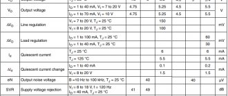
In the table you can see the electrical parameters for a typical test circuit. One of the columns shows the operating conditions of the device at no more than 25 degrees. Its limits are determined by the modification of the device. The given characteristics are often found in the L78L05 chip lines.
A typical test circuit contains capacitors with a capacity of 0.33 and 0.1 μF. It is supplied with a zero voltage of 10 V. Unless otherwise specified, the output current is 40 mA.
All the given data shows that all L78L05 are different in a number of values. You need to take a closer look at individual modification features. For example, if the designation of a device contains the letter B, this indicates its ability to function at low temperatures, up to -40 degrees. But the letter “A” at the end of the name is a sign of high accuracy in stabilizing the output voltage up to 4%. The symbol “C” indicates that for standard stabilizers this range is doubled.
There is nothing complicated in the classic circuit for switching on the device, in which testing is carried out. To create it you do not need to be a professional radio engineer or electronics engineer. It contains both the microcircuit itself and 2 smoothing capacitors. The input capacitance is always much higher than the output capacitance, since it suppresses external fluctuations from the electrical source. The output capacitance, in turn, is needed to suppress high-frequency ripples.
Smoothing capacitors, according to the manufacturer’s advice, are soldered close to the legs to reduce the level of interference and stability of operation.
Specifications
The first versions (as can be determined from various datasheets on the 78L05) were developed in the 1970s by the American Fairchild Semiconductor. Their appearance resembled a regular transistor, since it had three legs and that’s where the similarity ended. Inside the small case was a marvel of engineering, containing a whole range of electronic components.
Marking
The marking encrypts minimal information about electrical parameters. The numbers “78” indicate positive polarity, then “L” - a small current (up to 0.1 mA) and “05” - voltage (up to 5 V) in the connected load. At the end of the designation there are symbols that determine the accuracy of stabilization, the operating temperature range and the type of housing.
Currently, many companies have mastered the production of complete copies of 78L05. With this designation it is produced by the Chinese Wing Shing Computer Components (WS). Modifications of the American Texas Instruments, Fairchild (LM78L05) and STMicroelectronics (L78L05) are mainly common on the world market. In Russia, the most common versions are from STM, and we will consider them in this article.
Tsokolevka
Of particular interest is the pinout of 78l05 in smd version (SO-8), since it has 8 legs. At the same time, the classic version of this microcircuit in the TO-92 package is equipped with only three pins, with the following purposes: input, ground, output. However, their number should not be confusing, since some of them are not connected to anything or are electrically connected to each other inside the plastic packaging. To understand the pinout, it is better to look at the figure below, since for some manufacturers it does not coincide with the generally accepted one.
As you can see, the 78l05 (TO-92) pinout from WS is mirrored, which is why it differs from the STM and Texas Instruments standards. For many Chinese manufacturers it coincides with WS, for example Changjiang Electronics Tech (cj 78l05). It is worth considering this feature, as it may cause the circuit to fail.
Maximum parameters
In the vast majority of circuits, the L78L05 acts as a fixed voltage regulator of 5 V. Moreover, for its stable operation, 2-3 V more (from 7 V) must be supplied to the input than what is received at the output. If a good heat sink is provided, it can withstand an output current of up to 100 mA. Here is a list of the maximum parameters of this microcircuit.
- input voltage up to 30 V;
- output current up to 0.1 A;
- heating the crystal to +125°C;
- storage temperature -65 … +150С;
- power dissipation is limited by internal protection.
78l05 is structurally protected from overheating and short circuit.
Electrical parameters
Electrical ratings for the L78L05 are based on a typical test setup. The “Test conditions” column indicates testing conditions at normal crystal temperature (TJ) up to 25 °C. It must be within acceptable limits, depending on the modification of the device. Below is a summary table of electrical parameters of the most common L78L05 series microcircuits.
A typical testing circuit contains 0.33 µF and 0.1 µF capacitors. This uses a voltage of VO=10 V. Unless otherwise specified, the output current of IO is 40 mA.
As can be seen from the presented data, the L78L05 differ slightly from each other in individual values. There are some features of the modifications that are worth noting. For example, if the symbol “B” is present in the designation, then the device is capable of operating at low ambient temperatures (from -40°C). L78L05A, with an additional letter “A” at the end of the marking, have an increased output voltage stabilization accuracy of ±4%. And for ordinary “C” this spread is twice as large and amounts to ±8%.
How to test the 78L05 device using a multimeter
Before using the device, it must be checked with a multimeter. To do this, you need to ring the contacts to find out if there is a short circuit between them. If it is absent, the check continues.
The input voltage must be no less than 7 V, and no more than the maximum. For this, a regular crown with a voltage of 9 V is used. An additional load device, for example, a 1 Ohm resistor, is connected to the output.
When supplying power, observe polarity. The negative side is connected to the main terminal, and the “+” sign is connected to the input. The output voltage is disconnected from ground and is 5 V, according to the design of the chip.
Connection diagram
The classic connection circuit for L78l05 (aka test) is quite simple. Does not require professional knowledge in the field of electronics and circuit design. It contains the microcircuit itself and two smoothing capacitors of 0.33 and 0.1 µF. A larger capacity is always placed at the input than at the output. The first is to suppress oscillations from an external power source, and the second is to suppress high-frequency ripples.
The manufacturer recommends soldering smoothing capacitors as close to the legs as possible to reduce the level of interference and instability in operation.
Device analogues and manufacturers 78L05
In addition to the names already listed, there are several other types of device substitutes. Among them are foreign ones:
- TS78L05
- MC78L05
- TS78L05
- UA78L05
- MC78L05
Several high-quality accounts are also produced in Russia and Belarus, for example, KR1181EN5 and KR1157EN502.
Design of a laboratory source of electricity based on 78L05
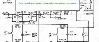
The design in question is original, since it uses an atypical TDA2030 microcircuit, but the source of electricity here is the 78L05 stabilizer. Since the maximum operating input voltage of this device is 20 V, so that it does not break, the work continues not without the participation of a parametric stabilizer.
To connect the TDA2030 device we use a non-inverting device. As a result, a specific gain indicator is created. As a result, the voltage at the output of the electricity source is adjusted from 0 to 30 V when the resistor value changes. If it is necessary to change the highest output voltage, a resistor of the appropriate level is selected for this.
Description of stabilizer 78L05
This stabilizer is not expensive () and is easy to use, which makes it easier to design radio-electronic circuits with a significant number of printed circuit boards to which an unstabilized DC voltage is supplied, and each board has its own stabilizer mounted separately.
The 78L05 (7805) stabilizer chip has thermal protection, as well as a built-in system that protects the stabilizer from overcurrent. However, for more reliable operation, it is advisable to use a diode to protect the stabilizer from a short circuit in the input circuit.
The only difference is the polarity of the output voltages. An adjustable voltage stabilizer is a type of regulator whose adjustable output voltage can vary within a range. There are two variations of the same thing; known as positive regulated voltage regulator and negative regulated voltage regulator.
There may be certain conditions where AC voltage may be required. The connection diagram is shown below. The required output voltage can be calculated using Eq. So the above equation can be rewritten as. Load regulation is 1 percent and linear regulation is 01% per volt. This means that the output voltage only changes by 01% for each input voltage voltage. The ripple hole is 80 dB, which is equivalent to 10.
5V power supply without transformer
The main distinguishing feature of this scheme is its high stability. Its elements do not heat up, and all of them are accessible to ordinary users.
The unit includes an LED on/off indicator. There is no usual transformer here; a damping circuit with certain capacitance and resistance values is used. The unit is equipped with a rectifier bridge based on diodes and capacitors to reduce vibrations, and has a 9 V zener diode. And of course, the circuit will not be able to work without a special voltage stabilization device - 78L05.
It is necessary since the output voltage of the bridge is approximately 100 V. Because of this, the stabilizer may break. The stabilization level is in the range from 8 to 15 V.
The design does not have isolation from the electrical network of galvanic elements, so you need to use the power supply more carefully.
Checking with a multimeter
Before using 78L05, it is better to check with a multimeter by ringing for a short circuit between the contacts. If there is no short circuit, then you can check further. At the input, you need to apply a voltage of at least 7 V or more, but within the maximum permissible. To do this, you can use a regular 9 V crown. It is advisable to connect a load to the output, for example a 1 kOhm resistor.
When supplying power, polarity must be observed. The negative should be connected to the common terminal (Gnd), and the positive to the input (VIN). The output voltage is taken from Gnd and VOUT. It should be 5 V (±8%), depending on the modification of the microcircuit.
78L05 Standard Power Supply
The spread of variable volts in the specified design takes limits of 5-20 V. The output voltage changes thanks to a resistor with variable values.
The maximum load current is 1.5 A. Here the device 78L05 is replaced with 7805 or its Russian version - KR142EN5A. Instead of VT1, another transistor, KT315, is also used. Possessing high power, VT2 is placed next to the radiator, which measures 150 cm2.
How charging works for different types of electronics
Let's look at a simple and widely used design. All possible lithium, nickel, and lead batteries used in uninterruptible devices are charged from the resulting device.
When the battery is being charged, the charger's amperage is of particular importance. Normally, it is approximately 1/10 of the battery capacity. The constancy of this value, in turn, is ensured by the 78L05 stabilizer.
There are 4 options for charging current spread, from 50 to 200 A. They depend on the resistance value.
With a stabilizer output voltage of 5 V, to obtain a current of 100 mA, you need to use a resistor with a resistance of 100 Ohms. And so - with each of the values.
In addition, the circuit has an indicator, which is based on 2 transistors and a light diode. The latter is extinguished when the charge runs out.
Technical parameters and pinout of stabilizer 78L05:
- Input voltage: 7 to 20 volts.
- Output voltage: 4.5 to 5.5 volts.
- Output current (maximum): 100 mA.
- Current consumption (stabilizer): 5.5 mA.
- Permissible input-output voltage difference: 1.7 volts.
- Operating temperature: -40 to +125 °C.
More circuits on adjustable voltage regulators
As shown in the block diagram above, there are built-in voltage references. There are many voltage amplification stages for the op amp used here. Thus, the current flowing through the potential divider can be written as. Thus, the output voltage can be written as: This increase in temperature may be mainly due to excessive external stress, ambient temperature, or even heat loss.
Pins 1, 2 and 3 are input, output and ground. Otherwise, it will stop regulating. In addition, there is a maximum input voltage due to excessive power dissipation. In switching regulators, the output voltage is regulated by controlling the switching time of the feedback circuit; that is, by adjusting the duty cycle. The regulators discussed above are linear voltage regulators that require a series transistor to regulate in the active region.
Non-DC power supply
The “negative” connection in the opposite direction goes through the load resistance. A certain number of volts are concentrated at the inversion input of the microcircuit (TDA2030). Under its influence, a current passes through the additional element. It does not depend on the load rating of the resistor.
It turns out that if you adjust the voltage that came from a device with variable resistance, with its constant value, the load current can be changed within 0.5 A. Using such a circuit, it is easy to charge any type of battery. Throughout the entire charging period, the current remains at the same level. It does not depend on whether the battery is discharged or how stable the electrical network is. The maximum charging current can be adjusted with a resistor by changing its resistance.
You can buy 78L05 and other devices of the 78Lxx type in China on the Aliexpress website using the link.