HF receivers
Broadcasting superheterodyne HF receiver with six transistors.
An important advantage of the HF range is its practically unlimited reception range. Thanks to tropospheric reflection, HF radio waves are reflected many times and can travel around the entire Earth. This is why very long-range reception is possible on the HF band even with a very simple radio receiver...
1 295 0
Direct conversion HF radio receiver on SA612AN (SSB and CW, 7 - 7.12 MHz)
The receiver is designed to receive SSB and CW amateur radio stations in the range 7 - 7.12 MHz. The schematic diagram of the receiver is shown in the figure. It is made according to a direct conversion circuit on two microcircuits - SA612AN and LM386N. The input signal from the antenna is fed to a single input circuit...
1 226 0
Direct conversion receiver for SSB and CW stations in the 7 MHz band
The receiver is designed to receive SSB and CW amateur radio stations in the range 7 - 7.12 MHz. The sensitivity with a signal-to-noise ratio of at least 3/1 is about 1 µV. Bandwidth is about 3 kHz. The schematic diagram of the receiver is shown in the figure. It is made according to the direct scheme...
1 62 0
Tri-band amateur HF radio receiver MARIA (MARIA) on SA612 and LM386
Schematic diagram of a homemade amateur HF radio receiver “MARIA” for wave bands: 80, 40 and 20 meters. A diagram describing this receiver was sent by one of our website visitors.
1 5315 2
HF broadcast receiver with seven transistors KT3102, KT3107 (3.5 - 22 MHz)
Thanks to tropospheric reflection, short-wave radio waves, repeatedly reflected from the troposphere and the surface of the earth, can travel around the entire Earth. Therefore, long-distance reception is possible on HF even with a relatively simple receiver. Despite this undoubted advantage, KB bands can be found ...
1 1888 0
Short-wave direct amplification receiver based on two transistors and a microcircuit
Direct amplification receivers were very popular among radio amateurs until the 90s, when there were many broadcast stations on medium and long waves. Then it was no longer the case - all the interest moved to the VHF range, and there the direct amplification circuit is not so effective. Now from the AM bands interest may...
2 3254 0
HF direct conversion receiver for 80 meters using a KP327 field-effect transistor
The receiver is designed to receive amateur radio stations with SSB or CW modulation operating in the 80M range. But by changing the parameters of the input and heterodyne circuits, it can be configured to receive in any other amateur radio HF band. The main feature of this receiver is that its...
1 2976 0
Circuit diagram of a KB receiver with a transistor detector for receiving broadcast radio stations
An important advantage of the HF range is its virtually unlimited reception range. Thanks to tropospheric reflection, HF radio waves are reflected many times and can travel around the entire Earth. This is why very long-range reception is possible on the HF band even with a very simple radio receiver...
1 3365 0
Regenerative HF receiver for the frequency range from 3 to 13 MHz
The circuit of a homemade regenerative HF radio receiver for the frequency range from 3 to 13 MHz is made using MPF102, 2N2222 transistors and an LM386 microcircuit. The peak of the era of regenerative receivers in professional and amateur radio equipment falls on the late 20s or early 30s of the last century...
2 4100 0
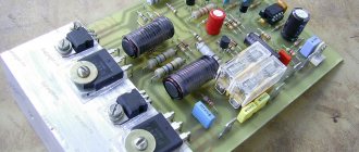
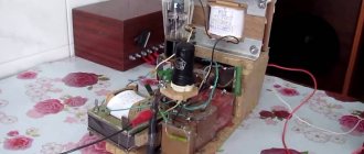
Homemade HF regenerator using 6Zh5P and 6F1P lamps (41m)
The topic of tube HF regenerators for broadcast bands on the network has a place among a wide audience of radio amateurs. Despite the fact that this reception technology is already several decades old, such designs are still quite relevant today. Without claiming originality, I want to make my contribution in the form of a simple regenerator for the 41m range. The receiver has only two lamps and the required minimum of parts.
3 4232 5
1 …
How radios became consumer goods
Progress does not stand still: over the course of the previous century, the cost of radio receivers decreased, while their characteristics became increasingly better. So, in the 20s of the 20th century, the main contribution to the cost was made by radio tubes - just remember Armstrong’s first superheterodyne, which we already mentioned when talking about the history of the superheterodyne.
At the time of its appearance, it seemed completely insane, since it contained eight lamps - a huge number for that time. But he also needed batteries with a total size of a small suitcase!
In the 1930s, such a receiver was already quite real and was even mass-produced, and in addition, indirect incandescent lamps appeared that could be powered from the network. And the prices are not so exorbitant. As a result, the receiver cost about the same as an iPhone now, and it could already be placed on the table without the risk of breaking the latter.
The next stage of cost reduction and miniaturization took place quite slowly, lamps became cheaper and smaller in size, and circuitry was improved. This continued until the 1960s. And the breakthrough happened in the early fifties, when the first serial transistors appeared and the first serial receiver, Regency TR-1, was built on them.
In terms of characteristics, it was inferior to tube ones of that time and cost significantly more, but it could already be put in your pocket. And then transistors gradually became cheaper, their parameters improved, and along with them, receivers became smaller and more economical. Integrated circuits appeared, and somewhere around the 1970s, the number of transistors in a device ceased to significantly affect the price. Intermediate frequency circuits and tunable input circuits began to make an increasing contribution to size and price.
The next breakthrough occurred in the early eighties, when Philips engineers managed to fit the entire radio frequency path into one chip. And besides, due to circuit engineering tricks, get rid of all circuits except the heterodyne one. The chip was called TDA7000, and the prototype of the receiver, presented for advertising purposes, looked quite unusual.
Receiver prototype on TDA7000
The thing turned out to be extremely successful, so soon the TDA7021 (PDF) with support for stereo coding and the TDA7088 (PDF) appeared, which added the ability to automatically search for stations. The latest chip used a small digital part, which was responsible for this very search. However, everything there was arranged quite primitively, but this design lasted quite a long time. These are exactly the receivers that were built into almost lighters in the early 2000s.
Russian developers, although lagging behind, adopted the experience, resulting in the famous K174ХА34 (TDA7021), K174ХА42 (TDA7000) and the very funny hybrid circuit SХА058.
SХА058
But the domestic manufacturer no longer had enough resources to create an analogue of the TDA7088, or, rather, there was no time for it. In any case, now all these chips are considered obsolete and are not produced, with the exception of clones of the TDA7088, but it, apparently, will not have long left.
Today the era of SDR/DSP receivers has arrived, in which the main signal processing is performed mathematically on digitized data, we already discussed this when we collected ZetaSDR. But there the processing of the digitized signal took place on a PC. Is it possible to do without a computer? Yes, easy: in 2001, Philips released the TEA5767 chip (PDF), which is a single-chip digital receiver. This chip required a minimum of wiring, had digital control and was positioned (PDF) as a convenient option for embedding in various gadgets such as MP3 players and mobile phones. Among its advantages are quartz frequency stabilization and the ability to decode stereo.
TEA5767 with full trim
A little later, a more advanced RDA5807 chip appeared. He got rid of the last oscillating circuit in the harness. Actually, there was no binding left, but the received range was noticeably expanded (64–108 MHz), and RDS support appeared. Sensitivity has become higher, so has the sound quality, and, what’s most surprising, this little thing is capable of driving 32-ohm headphones without an additional amplifier. And all this for less than ten rubles! Moreover, the chip is backward compatible with the RDA5807, and is generally capable of working without a control microcontroller. But it's still more fun with a controller.
RDA5807 with harness
But even all of the above is not the limit: you can also stuff a DV/MW/HF receiver into the chip, as is done in the KT0915 (PDF), AKC6951 (PDF) (here you can also receive the first few TV channels) and SI473X, about which we will continue to talk.
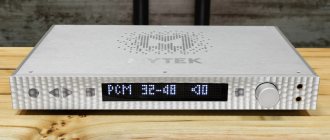
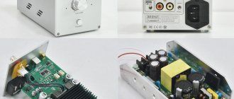
We will create a modern radio receiver similar to modern commercial examples such as the PL330 and ETON SATELLIT. But our product will be as simple and effective as possible.
PL330
ETON SATELLITE
High frequency tube models
Homemade tube HF high-frequency receivers include contact transducers and low-conductivity sensors. Some experts speak positively about these devices. First of all, they note the ability to connect transceivers. Triggers for modification are suitable for the controller type. The most common devices are those with semiconductor resistors.
If we consider the standard circuit, then the comparator is of an adjustable type. Output resistors are installed with a capacity of at least 3.4 pF. Conductivity does not fall below 5 microns. The controls are installed on three or four channels. Most receivers use only one phase filter.
Circuit design
For our experiments, we will assemble a relatively simple structure consisting of two blocks: a control unit and a receiver unit. We will assemble the control unit on STM32F030, add to it an encoder, an OLED display and eight buttons. You can completely abandon the buttons, but with them it is much more convenient to control the receiver. The PCF8574 will be responsible for the keyboard, a very convenient microcircuit - a port expander with an I2C interface. The introduction of a port expander, although it complicates the circuit, simplifies the board layout and button interrogation. It’s convenient to power this whole thing using a LiPO battery, so we’ll also add a charge controller and a DC/DC converter on the RT9136 to power the controller. The use of an active converter is advisable in terms of increasing efficiency.
Receiver circuit
The output power of the SI4735 is not enough to drive standard 32-ohm headphones, so we need an audio amplifier, even two, since we have stereo. The TDA2822 chip (PDF) in standard configuration was used as an amplifier. This is not the best option for two reasons: firstly, its gain is too high, and secondly, it is too noisy for my taste. The LM4863 (PDF) would be better suited for this role, but I didn’t have it on hand. Nevertheless, the TDA2822 copes well with its task.
Factory solutions usually use UHF and a magnetic antenna, but we’ll do it simpler: we’ll put a 5th order filter with a cutoff frequency at the input and use a full-size antenna - anyway, with the rod in the apartment you can only catch interference, FM and a couple of Chinese stations in good day. As for the FM input, it is comfortable without input circuits. In addition, we will place the SI4734 itself, along with the input circuits, in a screen made of tin (the board is double-sided, the other side is solid copper), fortunately this is not at all difficult. Using an external full-size antenna will greatly reduce interference from the digital part and eliminate UHF.
As for this very digital part, there are no special features here. The schematic, boards, etc. are on GitHub. Hanging a constantly updating display and keyboard on the same bus with the SI4734 is not a good idea due to possible interference, but stopping the controller and turning off the display by ear does not make any difference. From this we can conclude that in the city a much greater contribution to the quality of reception is made by air noise.
It is designed in a fairly minimalist style, however, I never liked making cases. I ended up with something between a prototype and a finished device, but the receiver survived transportation and field use without a wince.
info
Anticipating questions, I’ll say right away that the control unit can be assembled on both Blue Pill and ARDUINO; in the latter case, you can buy an already assembled board on Ali. It will cost about 3,000 rubles. And for additional money you can buy an additional housing for this case. But this is not our method, we are going to dig deeper with the SI4734!
Firmware
There are enough manuals on the Internet for assembling receivers on the SI4735, but most authors focus on circuit design and assembly on a breadboard, after which they upload one of the finished firmware options. We will try to figure out how to write such firmware ourselves almost from scratch, so everything that is said below is quite easy to transfer to any other microcontroller, as long as it has enough memory to store the patch.
So, what kind of animal is SI4734 and what is it eaten with? This chip is controlled via the I2C bus, and each message represents the address of the chip (with a write/read switch bit), 1 byte of command and up to 7 bytes of arguments. Each command has its own number of arguments, however, the datasheet says that sends can be made of a fixed length if 0x00 is sent instead of unused arguments. For our purposes, we won't need many commands, so we can afford to write our own function for each. The result of the command execution can be considered a response consisting of a status byte and up to 7 bytes of the response itself, and here, too, unification of the length is allowed: you can read 8 bytes, all unused ones will be 0x00.
But there is a nuance here: the command is not executed instantly, but with a delay, until the end of which the microcircuit will respond only with zeros. Therefore, when we need a response, we will read it at some intervals until the first byte of the response is equal to 0x80, which indicates the completion of the command. Next, you can read the response bytes and/or send the next command.
To send and read packets via I2C, we will use the LibopenCM3 library command already known to us i2c_transfer7(SI4734I2C,SI4734ADR ...), where SI4734I2C is the I2C bus (I2C1) used, and SI4734ADR is the seven-bit address of SI4734 0x11. The library will take care of the write/read bit for us. As a result, working with the microcircuit will briefly consist of the following sequence of actions: initialization, setting the operating mode, tuning to the desired frequency. Everything described below is based on the contents of the AN332 “Si47XX Programming Guide” and AN332SSB documents.
Modifications at 400 MHz
The 400 MHz device circuit involves the use of a dipole adapter and a network of resistors. The model's transceiver is used with an open filter. To assemble the device with your own hands, first of all, a tetrode is prepared. Capacitors for it are selected with low conductivity and sensitivity at the level of 5 mV. It should also be noted that receivers with low-frequency type converters are considered common devices. Next, to assemble the device with your own hands, take one modulator. This element is installed in front of the converter.
Low frequency devices
The circuit of a homemade HF low frequency receiver includes a controlled modulator, as well as a set of capacitors. Resistors for the device are selected at 4 pF. Many models have contact triodes that operate from converters. It should also be noted that the receiver circuit includes only single-pole transceivers.
To adjust the channels, regulators are used, which are installed at the beginning of the chain. Some models are made with only one adapter, and the connector for them is selected as a linear type. If we consider simple models, they use a grid amplifier. It operates at 400 MHz. Insulators are installed behind the modulators.
Models with two-junction converter
HF receivers for amateur bands with two-junction converters are capable of stably maintaining a frequency of 400 MHz. Many models use a pole zener diode. It is powered by a converter and has high conductivity. The standard modification circuit includes a controller with three outputs and a capacitor. The amplifier for the model is suitable with a varicap.
It should also be noted that high-frequency devices with a converter of this type can cope perfectly with impulse noise from the unit. Comparators are used with grid and capacitive resistors. The resistance parameter at the input of the circuit is about 45 Ohms. In this case, the sensitivity of receivers can vary greatly.
Single pole devices
Single-pole homemade HF tube receivers are easy to set up. The model is assembled with your own hands with variable comparators. Most modifications are designed with low conductivity stabilizers. The standard receiver circuit involves the use of dipole resistors with an output capacitance of 4.5 pF. Conductivity can reach up to 50 microns.
If you assemble the modification yourself, then the comparator must be prepared with a transceiver. Resistors are soldered onto the modulator. The resistance of the elements, as a rule, does not exceed 45 Ohms, but there are exceptions. If we talk about relay receivers, they use adjustable triodes. These elements operate from a modulator, and they differ in sensitivity.