This story happened 2 years ago.
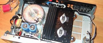
It might not have happened, but as they say, “the stars aligned” and this is what came of it. It all started with the fact that one of my friends, with the words “I don’t know what this is, take it for yourself or throw it away,” handed me a certain box. Inside were pieces of iron, 3 light bulbs, a transformer and other parts. Upon examination, it turned out that this is a headphone amplifier designer known as a lunch box. This was the first “star” that came together.
↑ How the stars aligned
I thought about whether to assemble the construction set or not for a couple of days. It turned out that one of my colleagues had this amplifier ready-made (“factory assembled”). This was the second “star”. I took it to listen. I listened to files in flac format on a macbook pro in the following configuration:
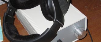
macbook → Optical cable → Cambridge Audio DacMagic DAC → The above amplifier → Beyerdynamic DT 770 Pro headphones When listening, it turned out that the sound was certainly much better than directly from the output of the sound card and better, than directly from the FM tuner, but something is missing. Doesn't live up to expectations. At least mine.
Here the third star came together. Namely: I remembered that not so long ago I read a note on Datagor, “We are building a simple SRPP tube amplifier for headphones.” And also Oleg Ivanov’s article “SRPP Headphone Amplifier”, in which a lot of attention is paid to the theory of the issue. In general, “three stars” were formed and I decided to assemble myself an SRPP in a housing from a designer. From the specified designer the following went into use: a housing, a transformer, a volume control and connectors.
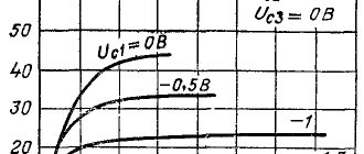
Three options for lamps for SRPP were considered: 6N3P-E, 6N23P and 6N6P. 6N6P consumes twice as much heat as the previous two, the existing transformer will not cope. And my headphones are high-impedance, I don’t need such a powerful lamp. Therefore, it was decided to try to assemble two prototypes for 6N3P-E and 6N23P, and then choose one as the final version.
Amplifier assembly
We ordered parts to build our amplifier from Aliexpress and assembled it in an aluminum case. Please note that the case needs to be spacious and well ventilated to cool the amplifier. At maximum volume, radiators without a housing heat up to 62 degrees.
The amplifier turned out to be nice and small in size. For details on how we assembled the amplifier, watch our video.
ICE125ASX2 amplifier testing video part 1
↑ Scheme
The diagram that I finally came up with is the following:
The power supply circuit for the amplifier is also quite standard:
The neon light here does not show ON/OFF, but signals that the fuse has tripped. Resistors connected to the filament winding create an artificial midpoint (to reduce background noise). The value of these resistors is 180 Ohm (0.25 W). The capacity in the anode rectifier is 220 microfarads / 350 V. Rectifier diodes FR205. Transformer from a construction set.
↑ Work
Because
I had time: “there’s no hurry,” and the reviews about SRPP were mostly positive, so I decided to make mock-ups with the aim of being able to insert them directly into the body. Those. in the form of normal working boards. The case is made in such a way that the amplifier should consist of two boards: on one there is a power supply unit (PSU) and a headphone jack, on the other the amplifier itself. Another small problem was that 6N3P-E and 6N23P have different pinouts, i.e. You can't just push them around. Therefore, we had to make one board for the power supply and two boards for the amplifier itself, for each type of lamp. The solution, as it turned out later, was not entirely successful, because it is not very convenient to compare the sound by resoldering the power supply. Final result: — Two boards for power supply, for this I had to buy another power transformer — One board for 6N3P-E lamps — One board for 6N23P lamps
The layout solution was as follows: use all the existing holes in the case, including: - two of the top holes for lamps (as intended by the manufacturer) - place the power electrolyte in the third hole (previously there was a third lamp there).
When wiring, it was also necessary to take into account that everything sticks up from the bottom board, and down from the top board, respectively. And it is necessary that these “stalagmites” and “stalactites” do not meet each other. And also that the lamps, electrolyte, volume control and headphone jack fit exactly into the holes existing in the housing.
The resulting layouts looked like this:
I set the models to “warm up the lamps.” Those. the amplifiers periodically turned on either idle, or listened to something. There was a sound. And it doesn't seem bad. I devoted several days while the light bulbs were “warming up” to searching for suitable cathode electrolytes. Several options were purchased: - Jamicon - Epcos - Elna Silmic II - Panasonic Electrolytes were looked for on the principle of “went to the store and bought it.” Those. of those available, including price.
Amplifiers on chips
A very simple solution - there is one microcircuit that only needs a power supply and minimal “piping” of radio components (several resistors and a couple of capacitors). There is no point in considering amplification microcircuits for less than 20 watts. If we are talking about quality, buying something below 20 W on chips is illogical.
And if low power is required, then it is better to look towards class A. And if you need something compact, powerful and efficient, look at Digital Amplifiers, Class D.
There are very few microcircuit amplifiers (in the AB class) from 20 W. The main ones, even 10 pieces are not enough .
New amplifier microcircuits have not been developed for a long time. Everything has been invented a long time ago.
For example, one of the most popular amplifier chips is TDA7294. And it was developed back in the last century. Time has selected several of the most successful circuit solutions (topologies) of microcircuits. Here is their full list (real watts) :
- LM1875 (single channel) 20 W
- LM1876 (dual LM1875) 2x20 W
- TDA2050 (single channel) 30 W
- LM4766 (stereo) 2x40 W
- LM3886 (single channel) 68 W
- TDA7294 (single channel) 70 W
- TDA7293 (single channel) 100 W
There are a huge variety of other microcircuits. But they will all be, literally, 5 rubles cheaper. And to a greater or lesser extent worse. The power limit of microcircuit amplifiers is 100 W. It happens that they are installed in the “bridge” to increase power, but we do not recommend this. It’s better then to immediately switch to transistor pairs. Microcircuits from the list we have indicated can easily be installed in expensive brand amplifiers sold in Hi-Fi salons for a lot of money.
Cambridge Audio 340A, based on the LM3886 chip, asked for about $500
The Chinese threw out the whole “Hi-Fi emptiness” and made their own laconic version of the amplifier on the LM3886:
LM3886 China amplifier, price about 8-9 thousand rubles. link
It has become many times cheaper ($110). The path is made much shorter, which is great for sound . The quality of the tires is simply incomparable, etc. But there is no remote control. Quality-oriented Chinese amplifiers almost never have a remote control. Typically, remote controls are installed only in the cheapest amplifiers. Usually these cheap amplifiers offer wild multifunctionality. More likely, it’s not even an amplifier, but a combine. Their customers believe that since they pay 1000 rubles, then the amplifier should have everything at once. And as much as possible. Quality issues are of little concern to these buyers. Our article is how not to buy such crap.
600 wattttt…. Price 1900 rub.
High-quality remote control of the amplifier (without introducing distortion into the sound) significantly increases the price.
In theory, this is a motorized potentiometer. The volume knob is turned by a motor for you, and the selection is made through a relay.
ALPS motorized, RUB 3,300, retail.
All other options are bad or very bad. Typically, switching and volume control microcircuits are installed in the audio path. And these microcircuits themselves introduce large distortions (sometimes many times greater than the amplification path itself). If the volume knob of the amplifier rotates in an endless circle, or the volume is adjusted with two buttons (louder and quieter), this is exactly the case when such microcircuits are installed in the path.
In Chinese amplifiers focused on sound quality, it is assumed that service functions will be at the signal source .
There is logic in this. Most sources can adjust the volume digitally. Many people use a computer as a source. And the remote control can be attached to any computer - details here. Also read our articles - Media player on PC., USB sound cards. And when adjusting the volume digitally, there is no need to install microcircuits in the amplifier path that introduce serious distortion. In this logic, the Chinese make their amplifiers without a remote control.
LM1875 Chinese amplifier
At low power, one of the best (in terms of distortion and sound) is the LM1875. The gap relative to other microcircuits is insignificant, but it exists. Its power is only 20 W. But these are real watts. As a guide, this is the same power as that of the radio equipment amplifier u-101, which was very popular at one time. The harmonic distortion of this amplifier was as much as 0.3% at 20 watts.
Radio engineering amplifier 101
LM1875 Chinese amplifier, price about 8 thousand rubles. reference LM1875, power - distortion. The chip is very good.
The Chinese write that it is 30 watt. They are exaggerating this a little. But there are a large number of amplifiers in the same or slightly modified housing. On microcircuits:
- TDA2050 30 W
- LM4766 40 W
- LM3886 68 W
When this case contains an LM3886 (68 W), in most cases, the power limitation will not be based on the chip, but on the power supply. A transformer for 68 W will need about 150 watts minimum. And the Chinese will bet less. And this case itself is unable to remove heat from a (stereo) 68 W chip.
TDA7293 Chinese amplifier
This is currently the most powerful microcircuit amplifier. There are no problems with it. But note that you can buy an all-transistor amplifier for almost this price. It should be understood that as soon as we come to powers of 100 watts or more, the cost of the semiconductors themselves ceases to be of particular importance. The price of powerful amplifiers is mainly found in the housings and power supply.
TDA7293 , Chinese amplifier, price about 14 thousand rubles .
TDA7293 power – distortion, at 4 and 8 ohms.
Amplifiers on microcircuits are quite good . Difficulties arise mainly when working under complex loads.
But this is a typical problem for Hi-Fi, described in detail in our article Why all Hi-Fi sounds like “who is in the forest, who is looking for firewood”
↑ Finishing
The fine-tuning involved the selection of cathode resistors from the point of view of reducing harmonics (the modes of the lamps, of course, must remain normal), as well as the selection of electrolytes in the cathode from the point of view of pleasant sound.
Resistors were selected by soldering a chain of a constant and trimming resistor into both cathodes of the lamp. Next, by applying a 1000 Hz / 0.75 V sinusoid to the input, we turn the interlinear and see what’s going on with the harmonics. In this case, a tester hangs on the lower cathode resistor, which shows the voltage drop (displacement on the grid). At first, Jamicon was used as a cathode capacitor. To view the harmonics, we used a USB oscilloscope, the program from which can also display harmonics. Of course, we also look at the beauty of the sinusoid. Real headphones were used as the load.
After the optimal resistor values were found, it was the turn of the electrolytes. The required cathode electrolyte was searched mainly by ear. There was also control for harmonics, but the difference there was not significant. To find the required electrolyte: a pair of candidate electrolytes were soldered through the switch and they simply switched while music was playing. So the difference is immediately noticeable. Of the two electrolytes, the “worst” one was then discarded, a new candidate was soldered in instead of it, and we listened again.
Over the course of several evenings, resistors and electrolytes were selected. It is worth noting that the anode voltage also plays a role in sound quality. I played around with it a little too. Eventually:
• from the available electrolytes, I left Elna Silmic 2 (in second place is Jamicon) • the resistor values and anode voltage obtained for each of the lamps are as follows: 6n23p: R4=R6=130 Ohm; Kt1 = 1.2 V; Kt2 = 140 V 6n3p-E: R4=R6=180 Ohm; Kt1 = 1.4 V; Kt2 = 260 V In fact, ideally, R4 is not equal to R6. But the “ideal” values did not fall into the existing denominations. Therefore, we had to look for the best value from the standard series of resistors.
As you can see, for 6n3p lamps the anode voltage is 260V. The transformer included in the specified constructor produces 170V alternating voltage at the output, which is clearly not enough. If these lamps are used, the power supply must be made according to a voltage doubling circuit, or another transformer must be used. In my case, I still had to purchase a second transformer, which turned out to be 210 VAC.
Other ratings of parts used in the circuit:
R1 - 50 K R2 - 100 K R3 - 1 K R5 - 22 K R7 and R8 are selected so that the anode voltage measured at C6 is as indicated above (Kt2). In my case (for a 6n3p-E lamp) the total resistance is R7 + R8 = 2 K. All resistors are 0.25 W. In addition to R7 and R8, these were set to 5W (there were no others).
Capacitors: C1 – 0.1 μF x 63 V (k73-17) C2 – 3300 μF x 10 V C3 – 1 μF x 250 V (k73-17) C4 – 200 μF x 250 V (Jamicon) C5 – 1 μF x 350 V (k73-17) C6 – 470 MkF 350 V C7 – 100 MkF 350 V
It would be worth noting that the quality of the wires through which the music runs to the amplifier also matters. Cheap thin wires, to my ear, produced “sand” on some compositions (usually such wires are supplied with various audio/video devices). Better use something more decent.
A selection of proven boards with good sound for assembling your own power amplifier
Do you want to assemble a power amplifier for home acoustics with decent sound yourself, but don’t know which option to choose?
Let's look at amplifier boards sold on Aliexpress. There is the widest range for those interested in sound. I purchased all of the options listed myself and used them in my DIY audio projects.
Let’s not be biased, and we will mention both traditional amplifiers: class AB, and modern ones with high efficiency: class D.
ICEpower ICE125ASX2 amplifier board
Buy here
The selection opens with a high-quality amplifier board from the title photo. This is the ICE125ASX2 from ICEpower® (a joint venture with the Danes Bang & Olufsen). These boards are used in high-quality studio monitors!
ICEpower ICE125ASX2 is the best class D I've listened to. The COM and MECC technology solutions used in this amplifier board had a positive effect on the sound quality. Documentation.
- Rated power: two channels 125 W at 4 ohms.
- Dynamic range: 121 dBA
- Operating frequency: 540 kHz
- Harmonic distortion + noise (1 W, 1 kHz): 0.003%
- Board dimensions: 160x80x35 mm.
Among the features of the board: the network switching power supply of the amplifier is integrated with it on one board. Therefore, there is no need to rack your brains over the power supply; a 230 V mains connection is connected. The board has an auxiliary voltage of 24 V. The connectors are included.
ICEpower ICE50ASX2 amplifier board
Buy here (Stereo) Buy here (BTL mono)
The younger brother of the first reviewed model ICE125ASX2. Documentation.
The ICE125ASX2 model is smaller and more powerful, but has the same high-quality sound. There are options for stereo boards or high power mono (BTL). The network power supply is also located on the board.
Characteristics:
- Rated power: 1%, THD+N, BTL mode, 1KHz 100W
- Rated power: 1%, THD+N, 1KHz 50W
- Distortion: THD+N 1kHz, 1W 0.002%
- Board dimensions: 11 x 8 x 3.5 cm
AB amplifier board with UPC2581V driver
Buy here
This is a class AB audio amplifier board. I recently reviewed it with measurements. The sound will not leave you indifferent.
This lot has several options for the set (I recommend taking it without a radiator, using your own):
- DIY soldering kit
- Assembled board
- DIY soldering kit + cooling radiator
- Assembled board + cooling radiator
For power supply you need a mains transformer with a secondary winding of 18 to 30 V with a midpoint.
Characteristics:
- Board dimensions: 155x120x50 mm
- Load impedance: 4-8 ohms
- Quiescent current: 50 to 60 mA
- Maximum declared power: 150 W per channel
- Driver: NEC UPC2581V
- Output transistors: NJW0302G + NJW0281G
Krell KSA-50 clone
Buy here
Discrete amplifier of class AB (can also work in class A) with two pairs of output transistors. The scheme is similar to the famous Lanzar. Power, high-quality sound and acoustic protection on the relay are already on the board.
Distortion measured SOI 1 W: 0.003%.
Requires a constant voltage supply with a midpoint.
Characteristics:
- Operating voltage: ±35V (Class A), when working in Class AB condition, the voltage can be increased accordingly to ±45V
- Output Power: 50W (Class A); 150 W (class AB)
- Output impedance: 4-8Ω
- Frequency Response: (-3dB): 20Hz-20kHz
- Board size: 160*95.5mm
Arylic Up2stream AMP V3 board
Buy here
This is a modern option for those who need more features. One small board contains: LAN, Bluetooth, WiFi, support for Airplay, DLNA, UPNP, multiroom and FLAC player via USB and, of course, a 2x50 W class D amplifier.
Characteristics:
- Power: 12-26 V DC
- THD: 0.03%, @ 1 kHz 50 W + 50 W 24V-4Ω
- WIFI: IEEE802.11 b/g/n 2.4G
- Bluetooth: 5.0, SBC/AAC
- Player file support: FLAC/MP3/AAC+/ALAC/APE/WAV
- Board dimensions: 110*80*22 mm
- Mobile application: 4STREAM
- Protocols: AirPlay, DLNA, UPnP, Spotify, Qplay
Delivery from Russia is available.
Amplifier board for TA2022
Buy here
Class D (more precisely T) amplifier board with pleasant sound. Here it is implemented: acoustic protection on the relay and the ability to work in BTL mode. And all this in a compact size. A small radiator is required for operation.
This amplifier is powered by AC (with a midpoint), recommended 22-0-22 V (maximum up to 40 V DC). The microcircuit produces 90 W (0.1% THD at +-31 V at 4 Ohms). There are all kinds of built-in protections.
Dynamic range: 102 dB
Board dimensions: 121*64 mm
Assembly kit for LM1875
Buy here
And the selection ends with a budget option for self-assembling an amplifier using LM1875 chips.
Surprisingly high-quality sound with low distortion, and there is acoustic protection on the relay.
Option with low power (up to 30 W) and compact size 99x63 mm.
Power supply 12-22 V AC with midpoint.
Short circuit and thermal protection. Good quality components.
I hope the selection of amplifier boards was useful and you will choose an amplifier to suit your taste and budget.
The amplifier board will be the heart of the project, but all that remains is to add power supplies, housing and accessories. We'll talk about this in the next episode.
Happy shopping!
↑ Compare and choose
The time has come to compare all 3 amplifiers (factory box and my two).
The amplifiers were compared in pairs. For comparison, a small board with sockets and switches was made, the purpose of which was to quickly switch the input signal between two amplifiers, as well as quickly switch headphones. In addition to me, 8 more people of different gender, age and musical preferences performed as listeners. Listening was usually done with each of them separately. Almost 3 weeks were spent on this (not every day, of course). The scheme is standard: we compare two amplifiers, put the “loser” aside, replace it with a third one and compare. The music was given to choose from what I had. Everyone listened to what they wanted. Clicking the switches, it was impossible to understand which amplifier was playing at the moment (I knew, of course, which one was playing). Thus, the bias in choosing the winner was minimal.
The results are:
— the “factory” amplifier was the first to be eliminated. This is not to say that he played poorly. I played normally. But, when compared, he lost. — opinions on 6N3P and 6N23P were equally divided. Both sound great. A little different. Everyone is good in their own way. I myself couldn’t decide which one I liked better. As a result: I took the one that was closer and began to assemble it as the final product. 6N3P was closer. Looking ahead, I will say that 6N23P also found use. She went to the next design (don’t waste your labor), about which next time.
About sound
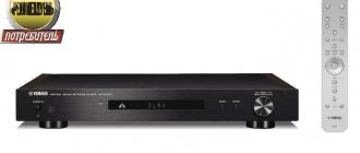
ICEpower ICE125ASX2 is probably the best Class D I've heard so far.
Very decent, no plastic tops. Compared with 2160, ICEpower does not sound flat, it is more developed in terms of volume, stage and sound microdynamics. My Krell 50 clone in class A ICE125ASX2 also outperformed in terms of sound quality, high frequencies cut through it immediately, as if cotton wool had been taken out of my ears. The subject lost only to the Jap amplifier. But the amplifier there weighs as much as half of me. And even then it was inferior in the delivery of the low-frequency range; nevertheless, an analog power supply with a high current potential sounds better on large floor-standing acoustics (I have a 3-way AVA one by Aleksandrov). The technologies (COM and MECC) used by ICEpower engineers in this amplifier module have a positive effect on sound quality. So, if you are hesitating whether to try it, make up your mind, this sound is obviously more expensive than the $100 that is being asked for it. Thank you for your attention! Happy designs!
↑ Installation Features
There are several points that I would like to pay attention to: - Structurally, resistors R5 are located on the bottom board (power supply board), next to the headphone jack. The remaining elements of the amplifier are located on the top board. — Capacitors C5 and C7 are located horizontally, on the underside of the upper board.
— Resistors R7 and R8, lamp sockets and capacitor C6 are located on the side of the tracks (on top of the board).
— Capacitor C6 needs to be thin and long so that it fits into the hole from the lamp in the upper part of the case. The Panasonic capacitor came up. The boards are connected to each other by wires. The wires are twisted together. Anode power and filament are supplied from bottom to top, and “output” to the headphone jack goes down from top to bottom. When wiring the boards, it was not possible to route the power from C6 directly to the lamps, so I ended up connecting the power with a wire. The filament between the lamps is also separated by wires (twisted together, as taught). Despite small liberties with the wires, there is no background in the headphones at all. At least no one heard him.
As for the connection itself with wires between the boards, I do this: I pass the wires through the board (through the “technological hole”), then the wires are bent and soldered in the right places. It's more reliable this way. The place where the wire is soldered is not subject to breakage, unlike the “insert into the hole from below and solder” method. The passage of the wiring harness through the board can also be fixed with hot glue. It looks something like this:
This method is especially helpful when working with MGTF wire. A good wire in all respects, but it often breaks off at the soldering point.
When assembling the final version (insert it into the case), it turned out that the power transformer gets quite hot. Up to 60 degrees, this is with the case not completely assembled. Most likely, this is due to the “closed” design of the case. In the assembled version, it may heat up even higher. There is practically no natural ventilation there. Well, I don’t like high temperatures on parts (except for lamps, of course). Therefore, it was decided to install a thermal fuse
.
Like this: This little thing, when the temperature exceeds 70 degrees, breaks 220 Volts, and when it cools down, it restores the connection.
It was attached directly to the transformer. Once, in the summer heat, it worked. The transformer is attached to the board with nylon ties covered in cambric. I like it better this way. Simple and reliable.
The wires from the input terminals to the volume control, for each channel, are pulled with a “double MGTF in the screen” placed in heat shrink. The screen, as taught, is connected to the ground on one side. In my case: at the volume control.
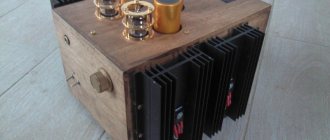
Complete refurbishment of the Radiotekhnika U101 amplifier
So I decided to try to write an article about altering the amplifier. Well, I’ll probably start with its history, namely why I decided to completely remake it. Firstly, everything is old and does not correspond to modern times. And secondly, he worked very hard before he fell into my hands, so he broke down more than once. The final stage was repaired 6 times, the tone block was repaired 2 times, there was something incomprehensible with the input selector, and besides, once they burned the indicator by connecting it incorrectly, but they installed another one from another amplifier, but I managed to burn it too when I picked his mustache. In general, let’s say, they passed this thing on to me as an inheritance. I decided to put an end to these glitches by redoing it completely.
Before the modification it looked like this:
Final amplifier. I wanted to insert something more interesting there, not some 7294, but something more serious. After googling for a week, I found what I needed.
The SymaSym 5 amplifier is an AB class amplifier, it suited me perfectly both in terms of characteristics and cost.
Scheme:
The parameters are:
THD: ~0.005% (measured) sim'd: 0.002% Power into 8ohm: 60 watts Power into 4ohm: 100 watts Gain: 32dB (~1:40) full output at 0.7v input (0.5v rms) Feedback: 57dB Phase margin: > 90° Supply voltage: +/- 36v Biasing: 55ma, 12.1mv across a single 0.22 ohm Frequency response: 3.2hz to 145khz (-1db) using 4.7uf input cap Phaseshift at 10khz: <3°
Aren't they beautiful characteristics? Without hesitation, I assembled 1 channel, and then completed 2. The sound quality is wonderful! A huge minus is that there was no printed circuit board for it in lay format, and I don’t know how to use it in other programs, so I had to overlay the drawing and convert the board to light. Now other people who want to build this amplifier will be able to replicate it without any problems. See appendices for fees.
And the main thing is that the power is about 100W per 4 Ohm load with a +-33V power supply. This is what you need! Although I was going to redo it, I decided to leave the transformer the same. When straightening to constant, there was a suitable voltage. Another plus, 2 of these amplifiers can work on the original radiator from the u101, without overload, tested! The heating of the radiator at full output power did not exceed 70 degrees for an hour, and I like to listen to music very loudly
A small guide to assembling and configuring the final amplifier.
The output transistors are a pair of 2SC5200/2SA1943, but in the original circuit there were MJL3281A/MJL1302A, and MJE15030/MJE15031 were replaced with 2SA1837/2SC4793. BC transistors are sold everywhere, there is no need to replace them with anything, they are common. I replaced BD135 with BD139, it works the same. But there may be problems with the MPSA18; if you don’t find them, you can easily replace it with the BC550, but when soldering it to the board, it needs to be rotated 180 degrees, because it has a MIRROR PIN, unlike the MPSA18.
The trimming resistor VR1 can be a vertical type 3296 multi-turn, or it can be a regular single-turn, I would advise taking a 3296, it’s easier to adjust the amplifier, when you first turn on the amplifier this resistor should have a MAXIMUM resistance.
Resistors R24 R25 0.22 Ohm for 5W cement. Resistors R22 R23 1.2 Ohm, 1 W each. Resistor R26 4.7 ohm for 1-2 W. Resistor R27 10 Ohm 2W, a coil of 10 turns with 0.8mm wire is wound on top of it. All other resistors are 0.25W.
Capacitors... It’s better not to put bullshit here. Electrolytic capacitors for power supply must be taken with a voltage reserve, mine is 50V with a power supply of +-33V.
Capacitor C3 470uF from 16V. The capacitor at the input of amplifier C1 needs a film capacitor, from 4.7 uF at 63 V, you can use yellow polypropylene, place it vertically, it will be ideal. It is very advisable to use film, but if you can’t find it, then we turn on 2 capacitors of 10 μF per volt with 50 minuses, and solder the extreme positives into the board, and it is advisable to add a film capacitor in parallel to the collecting capacitor, at least 1 μF.
C15 47nF 63V film cap, it is also advisable to put film in the power supply C9 C11 C16 C17.
The rest of the capacitors are ceramic, preferably NPO, but if you can’t find them, you can plug in Chinese brown ones, but I would look for something better.
Fuses from 2.5A.
In principle, that’s all, you can go collect.
Transistors must be installed on the radiator through insulating gaskets, and under no circumstances should they be short-circuited!
A properly assembled amplifier turns on immediately and can be listened to. It is better to do the first switching on through a lamp inserted between 220V and the primary winding of the transformer; if you make a mistake somewhere, the lamp will glow, but your parts will not burn out.
If you are fearless, you are confident in yourself and nothing interferes with you, then well, good luck, turn it on without a lamp, if something is phoning, humming or burning, immediately turn it off and look for errors. But it’s still better to compile without errors, google carefully for each plug, because if you make a mistake, the mistake can be costly.
Amplifier settings
Already collected? Wow! Congratulations. Now there's just a little bit left to do.
It is necessary to set the quiescent current within 50-70mA. I set it to 70mA.
For successful setup, the amplifier needs to be warmed up, just turn it on and listen to music for about 30 minutes, the fact is that until we set it up, it works in mode B, so it itself will not heat up.
How's the sound? Excellent of course. Now we need a multimeter. We set the measurement mode to millivolts, and connect the probes between the EMMITTERS of the first and second transistors, and set the desired quiescent current by slowly turning resistor VR1. For 70mA this is 30.8mV (U=I*R, U=70mA*(2*0.22 Ohm)=30.8mV).
That's all, congratulations! We do similar things with the second channel.
Tone block
Slightly modified diagram:
We unsolder the variable resistors from the tone block from u101, bite off the additional leads, and solder them into the board, after inserting the fastening die.
The operational amplifier here needs a “musical” one, NE5532 is recommended, but you can look for analogues, for example, I used RC4580IP, it was obtained from audio equipment.
All capacitors in the audio path are film! But in the power supply, electrolytes are 470 μF at 25 V. Resistors in the power supply are 1kOhm, 0.5W each. The remaining resistors are 0.25W each. I used 1N4743 zener diodes; unfortunately, there were no other less powerful ones.
No setup required, it works right away.
Attention! The board has an SMD jumper, or a 0 Ohm resistor on the track side. Don't forget to put it!
The payment in *.lay is in the applications.
power unit
Here you can choose what you prefer. I preferred caps of 22000 μF, but here it is advisable to parallel several capacitors so that the total is about 20000 μF; the total ESR of the capacitors will be less than that of a large one, therefore, at the peak it can deliver more current. A soft start turned out to be unnecessary here. I have KD2997 diodes. Film capacitors 1-4.7uF at 63V.
See the appendices for the power supply board.
How to connect a transformer?
Pins 2 and 2 are connected to each other. And connect 220 to pins 1 and 1.
Next... We connect pins 6 and 6 to the ground of the rectifier block, and connect pins 3 and 3 to the inputs of the rectifier block.
Now... We connect pins 7 and 7, and connect pins 8 and 8 to the indicator.
Protection block
Although you can leave the original one, I still decided to replace it. I used the Slap Mikruham, ready from the amplifier, by Ilya S. (Nem0). Protects from overload and from constant output, and from constant both from plus and minus relative to the ground.
Scheme:
All resistors are 0.25W. Transistor BD135 can also be replaced with BD139; it must be installed on a small radiator. Zener diodes for 12V and 13V, prefabricated, it turns out to be 25V. 24V relay.
Capacitors C1 C2 C3 C4 for 25V. C5 at 50V.
The payment is also in the applications. One board already has protection for two channels.
Indicator
Here I would have left the original indicator, but since I burned it when it was connected incorrectly, the fact is that they put another indicator there, I couldn’t find a circuit for it anywhere, presumably it was a radio constructor.
I assembled it on two LM3915.
Scheme:
All resistors are 0.25W. The outer LEDs “100W” are red, the rest are green. It is configured as follows: connect to the output of the amplifier and turn the tuning resistor, at maximum volume, so that the entire display scale is shown, and at minimum volume, so that the “0.2W” LED winks.
We do the same with the second indicator. When you turn on the indicator for the first time, set the variable resistor to the middle position.
Installation
Now we stuff everything into the body.
I came up with such fasteners for speaker connection terminals. Like this, I cut it out of PCB.
The die is painted and the terminals are screwed in.
I did the same for attaching the audio input sockets. I screwed everything up and screwed it down. Final look:
We connect everything with wires.
First food. We connect the power supply of the amplifiers to the rectifier block, we also connect the tone block board to the rectifier board, and we connect the protection board to the rectifier board in the +33V arm and ground, it won’t work otherwise! But we take the indicator’s power from terminals 8 from the transformer, through a diode bridge.
Next, we connect the shielded signal wires from the input connectors to the tone control unit, and from it to the input of the amplifiers. We take the signal for the indicator from the output of the amplifiers, the wires are not shielded.
We connect the output from the amplifiers to the protection board, and connect the protection board with wires to the terminals for connecting speakers.
We connect the transformer to the switch on the front panel, and from it to the 220V power connector. All! You can turn it on!
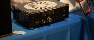
This is what I got from the inside:
What it looks like when fully assembled and working:
I would like to express my deep gratitude to Lyokha (finn32) for her help with the assembly! Good luck to all!
There is no need to mirror printed circuit boards.
List of radioelements
| Designation | Type | Denomination | Quantity | Note | Shop | My notepad |
| Amplifier | ||||||
| Q1, Q2 | Bipolar transistor | MPSA18 | 4 | can be replaced with BC550, mirror pinout | Search in the Otron store | To notepad |
| Q3, Q4 | Bipolar transistor | BC546 | 4 | Search in the Otron store | To notepad | |
| Q5, Q6, Q7 | Bipolar transistor | 2N5401 | 6 | Search in the Otron store | To notepad | |
| Q8, Q9 | Bipolar transistor | 2N5551 | 4 | Search in the Otron store | To notepad | |
| Q10 | Bipolar transistor | BD139 | 2 | Search in the Otron store | To notepad | |
| Q11 | Bipolar transistor | 2SC4793 | 2 | Search in the Otron store | To notepad | |
| Q12 | Bipolar transistor | 2SA1837 | 2 | Search in the Otron store | To notepad | |
| Q13 | Bipolar transistor | 2SC5200 | 2 | Search in the Otron store | To notepad | |
| Q14 | Bipolar transistor | 2SA1943 | 2 | Search in the Otron store | To notepad | |
| R4, R6 | Resistor | 680 Ohm | 4 | 0.25W | Search in the Otron store | To notepad |
| R1 | Resistor | 10 kOhm | 2 | 0.25W | Search in the Otron store | To notepad |
| R2 | Resistor | 10 ohm | 2 | 0.25W | Search in the Otron store | To notepad |
| R3, R7, R9 | Resistor | 22 kOhm | 6 | 0.25W | Search in the Otron store | To notepad |
| R5 | Resistor | 220 Ohm | 2 | 0.25W | Search in the Otron store | To notepad |
| R8, R16 | Resistor | 510 Ohm | 4 | 0.25W | Search in the Otron store | To notepad |
| R10, R14 | Resistor | 150 Ohm | 4 | 0.25W | Search in the Otron store | To notepad |
| R11 | Resistor | 68 Ohm | 2 | 0.25W | Search in the Otron store | To notepad |
| R12, R13 | Resistor | 47 kOhm | 4 | 0.25W | Search in the Otron store | To notepad |
| R15 | Resistor | 2 kOhm | 2 | 0.25W | Search in the Otron store | To notepad |
| R17, R18, R19, R20 | Resistor | 22 Ohm | 8 | 0.25W | Search in the Otron store | To notepad |
| R21 | Resistor | 33 Ohm | 2 | 0.25W | Search in the Otron store | To notepad |
| R22, R23 | Resistor | 1.2 Ohm | 4 | 1W | Search in the Otron store | To notepad |
| R24, R25 | Resistor | 0.22 Ohm | 4 | 5W | Search in the Otron store | To notepad |
| R26 | Resistor | 4.7 Ohm | 2 | 1W | Search in the Otron store | To notepad |
| R27 | Resistor | 10 ohm | 2 | 2W | Search in the Otron store | To notepad |
| VR1 | Trimmer resistor | 1 kOhm | 2 | 3296 | Search in the Otron store | To notepad |
| C1 | Electrolytic capacitor | 10 µF 63V | 2 | Search in the Otron store | To notepad | |
| C2, C6 | Capacitor | 100 pF | 4 | NPO | Search in the Otron store | To notepad |
| C3 | Electrolytic capacitor | 470 µF 50V | 2 | Search in the Otron store | To notepad | |
| C4, C9, C11, C13, C14, C16, C17 | Capacitor | 100 nF | 14 | NPO | Search in the Otron store | To notepad |
| C5 | Capacitor | 22 pF | 2 | NPO | Search in the Otron store | To notepad |
| C7, C8 | Capacitor | 330 pF | 4 | NPO | Search in the Otron store | To notepad |
| C10, C12 | Electrolytic capacitor | 100uF 50V | 4 | Search in the Otron store | To notepad | |
| C15 | Capacitor | 47 nF | 2 | NPO | Search in the Otron store | To notepad |
| C18, C19 | Electrolytic capacitor | 1000uF 50V | 4 | Search in the Otron store | To notepad | |
| Tone block | ||||||
| Operational amplifier | NE5532 | 1 | Search in the Otron store | To notepad | ||
| C1 C2 | Capacitor | 1 µF | 2 | 63V | Search in the Otron store | To notepad |
| C3 C4 | Capacitor | 3.3 nF | 2 | 63V | Search in the Otron store | To notepad |
| C5 C6 | Capacitor | 33 nF | 2 | 63V | Search in the Otron store | To notepad |
| C7 C8 | Electrolytic capacitor | 470 µF 25V | 2 | Search in the Otron store | To notepad | |
| Capacitor | 100 nF | 2 | Search in the Otron store | To notepad | ||
| R1-R4 | Resistor | 4.7 kOhm | 4 | 0.25W | Search in the Otron store | To notepad |
| R5-R10 | Resistor | 10 kOhm | 6 | 0.25W | Search in the Otron store | To notepad |
| R11, R12 | Resistor | 1 kOhm | 2 | 0.25W | Search in the Otron store | To notepad |
| R13 R14 | Resistor | 1 kOhm | 2 | 0.5W | Search in the Otron store | To notepad |
| VD1 VD2 | Zener diode | 15V | 2 | 1N4743 | Search in the Otron store | To notepad |
| VR1-VR3 | Variable resistor | 100 kOhm | 3 | TEMBER, BASS, BALANCE | Search in the Otron store | To notepad |
| VR4 | Variable resistor | 47 kOhm | 1 | VOLUME | Search in the Otron store | To notepad |
| Indicator | ||||||
| LED driver | LM3915 | 2 | Search in the Otron store | To notepad | ||
| Rectifier diode | 1N4001 | 2 | Search in the Otron store | To notepad | ||
| Diode | Diode bridge | 1 | Any on 1 | Search in the Otron store | To notepad | |
| Electrolytic capacitor | 22 µF 16V | 2 | Search in the Otron store | To notepad | ||
| Capacitor | 100 nF | 2 | Search in the Otron store | To notepad | ||
| Electrolytic capacitor | 470 µF 16V | 1 | Search in the Otron store | To notepad | ||
| Variable resistor | 22 kOhm | 2 | Search in the Otron store | To notepad | ||
| Resistor | 510 Ohm | 2 | 0.25W | Search in the Otron store | To notepad | |
| Resistor | 390 Ohm | 2 | 0.25W | Search in the Otron store | To notepad | |
| Resistor | 2.7 kOhm | 1 | 0.25W | Search in the Otron store | To notepad | |
| Light-emitting diode | Green | 20 | 20mA | Search in the Otron store | To notepad | |
| Light-emitting diode | Red | 2 | 20mA | Search in the Otron store | To notepad | |
| Protection | ||||||
| VT1, VT2 | Bipolar transistor | 2N5551 | 2 | Search in the Otron store | To notepad | |
| VT3, VT4 | Bipolar transistor | BDX53 | 2 | Search in the Otron store | To notepad | |
| VT5 | Bipolar transistor | BD135 | 1 | Search in the Otron store | To notepad | |
| VD1, VD2 | Rectifier diode | 1N4148 | 4 | Search in the Otron store | To notepad | |
| VD5 | Zener diode | 1N4742 | 1 | Search in the Otron store | To notepad | |
| VD6 | Zener diode | 1N4743A | 1 | Search in the Otron store | To notepad | |
| C1, C2 | Electrolytic capacitor | 47 µF 25V | 2 | Search in the Otron store | To notepad | |
| C3, C4 | Electrolytic capacitor | 220 µF 25V | 2 | Search in the Otron store | To notepad | |
| C5 | Electrolytic capacitor | 220 µF 50V | 1 | Search in the Otron store | To notepad | |
| R1, R5 | Resistor | 1 kOhm | 2 | 0.25W | Search in the Otron store | To notepad |
| R2, R6, R13 | Resistor | 1.5 kOhm | 3 | 0.25W | Search in the Otron store | To notepad |
| R3, R7 | Resistor | 4.3 kOhm | 2 | 0.25W | Search in the Otron store | To notepad |
| R4 | Resistor | 5.6 kOhm | 2 | 0.25W | Search in the Otron store | To notepad |
| R9-R12 | Resistor | 47 kOhm | 4 | 0.25W | Search in the Otron store | To notepad |
| K1, K2 | Relay | 24V | 2 | Search in the Otron store | To notepad | |
| power unit | ||||||
| Electrolytic capacitor | 22000 uF 50V | 2 | Search in the Otron store | To notepad | ||
| Capacitor | 1 µF 63V | 2 | Search in the Otron store | To notepad | ||
| Diode | KD213 | 4 | Search in the Otron store | To notepad | ||
| Add all | ||||||
Attached files:
- signets and diagrams(1).rar (565 Kb)
Tags:
- Sprint-Layout
- ULF
↑ Total
The finished structure begins to take shape:
Pay attention to the electrolytes on the top board.
They must be soldered with a gap from the board of approximately 3 mm. This is necessary so that during assembly they do not interfere with the sides of the case. There was an extra hole on the face of the case. In the “native” version there was a headphone switch. For low-impedance headphones, this switch, in series with them, turned on additional resistance. I decided to close this hole by inserting a neon light connected in parallel with the fuses (thermal and normal) so that it would light up if the fuse blows. The neon didn't fit in a bit, and when I was drilling it out, something sad happened: the panel got scratched. At that moment, a kind person said: “Black is bad, make it silver.” I tried to paint the face silver. The scratches were painted over, but I didn't like the idea. That's why I didn't repaint everything silver. But the muzzle remained silver.
The “NETWORK” LED was set to blue (from the designer), powered by incandescent power through a quenching resistor. Of course, a yellow LED would have been better, but there wasn’t one, and then I was too lazy to redo it.
As a result, the following design was assembled:
I listen with the volume control position “slightly below half” (actually as in the photo). That's enough.
frequency response
Beyerdynamic DT 770 Pro as a load
In conclusion, I would like to say that despite the simplicity of SRPP, the sound is decent. Also, do not neglect basic settings (in particular cathode resistors and capacitors).
Thank you for your attention and good luck with your designs!
A short introduction.
ICEpower® was founded in 1999 as a joint venture with the renowned Bang & Olufsen (B&O). The company's office is located in the suburbs of Copenhagen. You can read about the history of the company here. The company's developments are used, for example, in studio monitors, including this ICE125ASX2 board (2x125 W). Characteristics:
Bandwidth (-3 dB, 8 Ohms, half-bridge mode): 120000 Hz Operating frequency: 540 kHz Harmonic distortion + noise (1 W, 1 kHz): 0.003% Frequency response unevenness in the range of 20-20000 Hz at a load of 2–8 Ohms: ±0.5 dB Rated power (harmonic distortion + 1% noise, half bridge): 125 W/4 ohms Rated power (harmonic distortion + 1% noise, bridge): 450 W/4 ohms Maximum power (harmonic distortion + noise 10%, bridge): 550 W/4 ohms Rated power (harmonic distortion + noise 1%, half bridge): 65 W/8 ohms Rated power (harmonic distortion + noise 1%, bridge): 250 W/8 ohms Maximum power ( harmonic distortion + noise 10%, bridge): 300 W / 8 ohms Dynamic range (half-bridge mode): 117 dBA Dynamic range (bridge mode): 121 dBA Damping factor (8 ohms, 100 Hz): >500 Overall board dimensions: 160x80x35 mm. Technical information from the manufacturer The board is supplied in a cardboard box with additional packaging material: Inside there is an antistatic bag:
And a bag with additional accessories, these are brass stands for the board and connectors with contacts. ICE125ASX2 board: There are many unusual technical solutions here. Let's start with the most obvious - a switching power supply is integrated with a power amplifier on one board. The power supply is optimized to work together with the amplifier, and there is no need to pull wires. From the sides:
Top-bottom of the board:
The connectors are not clearly labeled. Here is the connection: DC 24-0-24 V low current output for auxiliary devices. Stereo input connection:
For respectable gentlemen, there are ready-made cables available for purchase for only $20)): but soldering yourself takes 5 minutes.
Unlike other Class D amplifiers, the ICE125ASX2 operates at 540 kHz. Therefore, neither the frequency itself nor its harmonics can be heard, since they are in the frequency range that humans cannot hear. And a plus - feedback directly from the amplifier output (after the output filter) does not curve the frequency response depending on the load resistance. Graph of amplifier distortion versus power:
Measurements-comparisons with more expensive colleagues in class D:
And overall, an interesting video from a character well-known in narrow circles.
I am starting assembly in a body of my own making. I wrote about him here.
The volume control with input selector is like this only for the practicality of using the amplifier. Assembly inside the case: I didn’t need additional 24 V; the volume control board on the PGA2311 is powered by its own network transformer.
Output power measurement (at 4.5 ohms). 1V input signal:
0 dB - 23 W
+10 dB - 116 W, above it curves a sine wave. The power is sufficient for domestic use.
Appearance of the finished amplifier:
Player under amplifier Aune X5S 6th. View of the device screen without flash: automotive tint film was used. Rear cable connections:
As a result, I placed the amplifier near the computer, instead of 2160:
It’s trivial, because it is more powerful, although it takes up more space. Of the minuses, there is a slight pop when turned on, but this is a transient process of the preamplifier on the 2311.