Many motorists are interested in the process of choosing a high-quality acoustic system, while simultaneously clarifying how it is possible to make a bandpass with their own hands. Most often, the acoustic system is connected according to several schemes, namely, using a closed box, a bass reflex, and bandpasses of various orders.
At the same time, it is possible to clarify that it is quite possible to make high-quality acoustics with your own hands according to the drawings of specialists, including that they can be made not only of 2 orders, but also of a maximum of 12 orders.
It is worth noting that correct calculation of the order of a hand-made bandpass, as well as equipping it with a subwoofer, can significantly reduce the noise of a vehicle, and at the same time enjoy high-quality and crystal clear sound.
Characteristics and calculation of bandpass orders
Many motorists are interested in the process of choosing a high-quality acoustic system, while simultaneously clarifying how it is possible to make a bandpass with their own hands. Most often, the acoustic system is connected according to several schemes, namely, using a closed box, a bass reflex, and bandpasses of various orders.
At the same time, it is possible to clarify that it is quite possible to make high-quality acoustics with your own hands according to the drawings of specialists, including that they can be made not only of 2 orders, but also of a maximum of 12 orders.
It is worth noting that correct calculation of the order of a hand-made bandpass, as well as equipping it with a subwoofer, can significantly reduce the noise of a vehicle, and at the same time enjoy high-quality and crystal clear sound.
Characteristics of 4th order bandpass
It is worth immediately clarifying that a 4th order bandpass (Qts≈0.4) is the most effective among similar bandpasses. If the device contains 4th order, then it is capable of using a subwoofer, which has an expanded bandwidth. However, even in this case, according to numerous drawings, it can be understood that the output will be slightly limited, since the band itself will be narrow and characterized by increased efficiency, but the bell will have low tones.
Three-chamber subwoofer BP-4
At the same time, a 4th order bandpass is an unusual thing, since it is almost impossible to make an accurate calculation without the appropriate professional skills. By the way, making an acoustic system with your own hands, the orders of which are limited to four, will be labor-intensive and capricious.
A high-quality box allows you to hide the speaker in it as deeply as possible, so it is impossible to damage this object and there is absolutely no need to install filters.
Bandpass 4 orders
How to calculate a subwoofer?
- Banshee
Wrong and correct ways to measure the equivalent volume of a loudspeaker head
Measurement data to calculate the total quality factor according to clause 1.1.2.1 in the source must be taken in a specially prepared room, see above.
- According to clause 1.1.2.3, it is unacceptable to measure the equivalent volume of the GG by radiation into a box with a slot (pipe?) as shown there in the figure. Get a price for firewood in Tiksi Bay at the height of female polar bears' heat. The tested GG must radiate into a sealed non-resonating box, see Fig. on right. At home it is easy and inexpensive to glue it together using PVA foam from 20 mm. There will be a slight waste of material on the seams during disassembly and the sheets will still be used for insulation or something else.
- With all due respect to the author, upholstering the inside of a sub with batting is not even yesterday. Batting, neither today, nor yesterday, and in general has never been a good sound- and vibration-absorbing material. For information on the internal anti-acoustic lining of the subwoofer, see above.
And still…
Making a subwoofer yourself is a fascinating task, useful for the development of intelligence and skill, and besides, a good bass speaker costs one and a half times less than a pair of a lower class. However, during control auditions, both seasoned experts and casual listeners “from the street”, all other things being equal, clearly prefer sound systems with full channel separation. So first think about it: won’t you still have to deal with a couple of separate speakers on your hands and your wallet?
Advantages and disadvantages of 6th order bandpass
The branded 6th order bandpass, enclosed in a high-quality and reliable box, has a number of main advantages:
- excellent reproduction of maximum low frequencies;
- reduction of mechanical loads;
- damping of diffuser vibrations occurs;
- increased response in the upper bass and reduced distortion;
- the ability to provide high-quality cooling of the magnetic system;
- easy installation;
- the simplest design of an acoustic system bandpass;
- the ability to reliably protect the 6th order bandpass diffuser from any external damage.
6th order bandpass
At the same time, the 6th order bandpass also has several disadvantages:
- increased sizes;
- complexity of design, since if installed incorrectly, low-quality and slightly unpleasant sound immediately occurs;
- complexity and labor-intensive manufacturing, which is beyond the capabilities of beginners;
- the presence of filtering properties allows you to mask all distortions if the device limits the signal;
- it is impossible to notice in time that the amplifier is overloaded and understand that the sixth-order bandpass has completely failed;
- the need to replace one of the mid-bass links;
- all technical characteristics will depend on the nature of the settings.
6th order bandpass
Materials used in production
Currently, several materials are used to make speakers, each of which has its own specific advantages:
- Multilayer plywood. It has a low cost, but is easy to process;
Plywood subwoofer
- Chipboard consists of natural materials, due to which its properties are significantly increased;
- Fiberboard has a fairly dense structure, so it is highly resistant to moisture.
About computer calculations
Color music
Do not think that JBL SpeakerShop or other acoustics calculation program will give you the only possible, most correct option. Computer programs are written using established, proven algorithms, but non-trivial solutions are impossible only in theology. “Everyone knows that you can’t do this. There is a fool who doesn't know this. It is he who makes the invention” - Thomas Alva Edison.
SpeakerShop appeared not so long ago, this application was developed very thoroughly and the fact that it is used very actively is an absolute plus for both developers and amateurs. But in some ways the current situation with him is similar to the story with the first photoshops. Who else used Windows 3.11, remember? - back then they just went crazy with image processing. And then it turned out that in order to take a good picture, you still need to know how to take photographs.
Amplifier connection diagram
Connecting a two-channel and four-channel amplifier
Bosch GS-10 vacuum cleaner review: guarding order
We have combined this section because these amplifiers have a very similar connection diagram, one might even say more simply, a four-channel amplifier is two two-channel ones. We will not consider connecting a two-channel amplifier, but if you figure out how to connect a four-channel amplifier, then you will not have any problems connecting a two-channel amplifier. Most car enthusiasts choose this option for their installations, since this amplifier can connect 4 speakers, or 2 speakers and a subwoofer. Let's look at connecting a four-channel amplifier using the first and second options.
Connecting a 4-channel amplifier to a battery is recommended using a thick cable. How to choose the right power wires and connect the interconnects, we discussed all this above. Amplifier connections are usually indicated in the manufacturer's instructions. When an amplifier is connected to an acoustic system, it operates in stereo mode; in this mode, this type of amplifier can operate under a load of 4 to 2 ohms. Below is a diagram of connecting a four-channel amplifier to speakers.
Now let's look at the second option, when speakers and a subwoofer are connected to a four-channel amplifier. In this case, the amplifier operates in mono mode, it takes voltage from two channels at once, so try to select a subwoofer with a resistance of 4 ohms, this will save the amplifier from overheating and going into protection. Connecting a subwoofer will not be a problem; as a rule, the manufacturer indicates on the amplifier where to get the plus to connect the subwoofer, and where to get the minus. Take a look at the diagram of how to bridge a 4-channel amplifier.
Connecting a monoblock (Single channel amplifier)
Single-channel amplifiers are used for only one purpose - connecting to a subwoofer. A notable characteristic of amplifiers of this type is increased power. Monoblocks are also capable of operating with resistances below 4 ohms, which is called a low-impedance load. Monoblocks are classified as class D amplifiers, and they have a special filter for cutting frequencies.
Installing a single-channel amplifier will not require much effort, since its connection diagrams are very simple. There are only two outputs - “plus” and “minus”, and if the speaker has only one coil, then you just need to connect it to it. If we are talking about connecting two speakers, then they can be connected either in parallel or in series. Of course, you don’t have to limit yourself to just two speakers, but before you connect the amplifier and subwoofer to the radio, will the latter cope with a high level of resistance?
Problems with subwoofers
Most problems can be solved by simply adjusting the frequency and phase. If such manipulations are not provided initially or you are using a passive subwoofer, you will have to try to place it in the room in order to find that very “point” of correct location. If you need high-quality sound from your speakers, then BandPass is certainly the best choice. This is one of the most effective subwoofers with various design variations and combinations of different types of designs. In addition, you can install such a device without any problems with your own hands. This can be done even at home. However, in the process of work it is necessary to view photos on this topic. Detailed instructions recorded on video may also be needed. The price of the device depends mainly on which company manufactured it. However, you need to look not only at the cost, but also at the technical data.
Peculiarities
The main feature of the bandpass is that it has a natural low-pass filter, which made it popular in the past when “natural” filters were the usual way to separate frequency bands. But after the advent and spread of specialized bass amplifiers with active filters, this factor became insignificant. In addition to their features, bandpasses also have bright advantages, which is why they are used in car audio, although not as often compared to other types of design.
Pros:
- High quality low bass
- Efficiency higher than that of ZYa and FI
- The subwoofer is protected from external influences
Minuses:
- Relatively narrow frequency range
- Complexity of calculation and manufacturing
- The required volume is greater than that of ZY and FI
Bandpasses are found in the 4th and 6th orders. The order is the slope of the filter.
n - filter order
Bandpass subwoofer - the best design
The bandpass subwoofer is a device that is increasingly used by modern drivers in cars. The bandpass subwoofer has a number of specific advantages over other models, which makes it indispensable for many car owners. Many companies well known in the car audio world produce subwoofers of this design.
CV, Bandpass 4 or 6? — Daewoo Nexia, 1.5 l., 2006 on DRIVE2
In short, I tried to collect all types of boxes. Results:
The 4th order power supply is assembled using the program for calculating boxes:
BP 4
— When the trunk is open, the bass disappears in the cabin, and you can’t hear the bass on the street.
6th order power supply unit (made in a box from a power supply unit 4 with minor modifications)
BP 6
I just refused to play, on any songs it plays like a speaker, on subwoofer tests it buzzes unpleasantly
CV (assembled with my eyes closed, just for testing, I’ll redo it later, also in the same box from under BP4)
CHV
CHV
(And in my case, the build quality is poor, I did it for fun and not for quality, so there are places where it misses a little)
RESULT: The box has a huge impact on the sound quality, this is why I bothered with all the boxes.
The CV turned out to be the loudest and most useful box.
↑ Now on technology
Since we require maximum rigidity from a low-frequency box, I have long abandoned corner blocks in the manufacture of such structures; moreover, I don’t like the fact that they steal volume from a carefully calculated system. Only tenon assembly will provide us with maximum rigidity. A spike of 10-15 cm is sufficient. How this happens is clear from the sketches and photos.
In addition, we use wooden pins, there are plenty of them in construction stores of different diameters, but only 6 mm is suitable for us - the optimal ratio for a standard 16 mm chipboard sheet (preferably, veneered, of course). For each tenon there are at least two pins, mutually perpendicular. They drill, fill the hole with epoxy, hammer the pins (you need to let the resin soak in for about 10 minutes and, under no circumstances, heat it before gluing - it will set too quickly). When the epoxy comes out, cover it with polyethylene so that you don’t wipe it off your face; you can leave the polyethylene until it dries so that it doesn’t spread. I don’t like self-tapping screws; they can be used as a temporary connection during assembly, then we turn them out and drill a hole for the pin.
↑ Collecting
We assemble it so that it is smooth - when done beautifully, it ALWAYS works better, tested not only on speakers.
To do this, we use the speaker cover, it must be made to zero in two copies, sanded and the edges adjusted. First, we assemble the head shield + side panels + bottom panel + frame. We put the covers on both sides and fix them with clamps or just a rope (tight). We check that everything is level, fix two screws on each side, check again and drill for the pins. When it dries, you can assemble the rest except the top panel. Then we cover all the corners with tape and fill each seam with resin from the inside. To do this, we place it at an angle of 45 - the seam will be smooth, and the tape will prevent the resin from leaking out and getting dirty. If there were any mistakes, the resin will fill everything and fix it, and also give it solidity. And so each seam dries, trying to ensure that the resin saturates everything as deeply as possible (it is not possible to close the seams of the head shield with tape, here you will have to use plasticine, but not a lot so that you can clean it later).
The top is placed last, also covered with tape and poured through the hole under the speaker. If everything is dry, peel off the tape and sand the corners from the outside. Now you can see how much the tape made the task easier. Next we putty and finish to your taste. I use auto putty and cover it with leatherette (black) with metal corners. I didn’t cover the inside with anything, just stuff it with padding polyester or cotton wool, sew it well into a large mesh bag, then it definitely won’t come out.
How to make bandpasses with your own hands
It is quite possible not to spend money on purchasing a high-quality, reliable and branded bandpass subwoofer. At the same time, on the Internet it is possible to find high-quality drawings of bandpasses, which will in no way be inferior to the most expensive gadgets produced by the Pride company.
Drawing of a 6th order bandpass subwoofer
When making your own bandpass, you should pay attention to high-quality drawings that have already been tested in practice by real professionals. It is worth noting that the entire design of a hand-made bandpass depends on what kind of loudspeaker was chosen
The fact is that the case is reliable, however, it is quite sensitive, since the narrowness of the frequency band directly depends on such an indicator as Qts
It is worth noting that the entire design of a DIY bandpass depends on which speaker was chosen. The fact is that the case is reliable, however, it is quite sensitive, since the narrowness of the frequency band directly depends on such an indicator as Qts.
Bandpass housing design
The lower this indicator is, the wider the frequency band will be, however, other characteristics will be incredibly unstable. That is why all calculations should be made as carefully as possible and ideally with the help of professionals.
In this case, the deformation coefficient of the loudspeaker will not have any influence on the complete design of the bandpass.
Calculation of the required volume, type of housing
Making a cabinet for a woofer begins with determining the type of cabinet we need. The boxes are:
- with open body;
- with a closed body;
- with bass reflex;
- bandpass housing.
The type and volume of the case is quite easy to determine. To do this, you will need to know three speaker characteristics (the optimal speaker size for a car subwoofer is 12 inches), they are indicated on the subwoofer box or in the instructions, you can also find these characteristics on the manufacturer’s website:
- Fs – natural resonance frequency;
- Qts – total quality factor of the speaker;
- Vas is the equivalent volume of the speaker.
The housing type is determined by dividing the resonance frequency Fs by the speaker quality factor Qts:
- Fs/Qts>30 – open case;
- Fs/Qts>50 – closed housing;
- Fs/Qts>85 – bass reflex;
- Fs/Qts>105 – bandpass.
So, we have decided on the type of case, how to calculate the required dimensions based on the given volume Vas? It is best to calculate the subwoofer enclosure using special programs such as Perfect Box 4.5, Blaubox, VASCalc. Using such programs, you can calculate boxes of any geometric complexity. These programs are shareware, so no problems with the law. To ensure that the subwoofer fits well in the trunk and does not take up useful space, approach the measurement process with all seriousness; the future box should fit where you intended.
Car subwoofers
Car subwoofers are usually placed either in the cargo compartment, or under the driver’s seat, or behind the back of the rear seat, pos. 1-3 in Fig. In the first case, the box takes up useful volume, in the second, the sub works in difficult conditions and can be damaged by feet, in the third, not every passenger will be able to tolerate powerful bass right next to their ears.
Car subwoofers
Recently, car subwoofers are increasingly being made of the stealth type, built into the rear fender niche, pos. 4 and 5. Sufficient sub-bass power is achieved by using special auto speakers with a diameter of 12” with a rigid diffuser, which is little susceptible to the membrane effect, pos. 5. How to make a subwoofer for a car by molding a wing niche, see next. video.
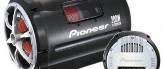
Review of the Mystery MBP-2500 model
For example, let's take the first BandPass subwoofer we came across - the Mystery MBP-2500.
| Construction type | Bandpass4 |
| Coating | Made from MDF (plywood) |
| Frequency range that this subwoofer can reproduce | 30 to 150 Hz |
Note. Typically, numbers like “speakers.subwoofers” are used for designation. For example, in a multi-channel system with five speakers and one subwoofer, the designation will look like this - “5.1”.
Mystery bandpass subwoofer
Subwoofer BaundPass 6 order
I offer all lovers of good, solid bass a closed-type subwoofer design.
Nowadays, all audiophiles lack conventional stereo sound; they want at least a 2.1 system. And for such a system, in addition to the left and right speakers, a third one is needed - a subwoofer.
Normally, the design of a subwoofer should begin with the selection of a low-frequency speaker (size, power), then having the parameters of the speaker and using one of a number of well-known programs for calculating subwoofers, obtain a drawing of the box.
I had a low-frequency head, 8 inches in size. According to the design, the execution decision was made - BaundPass 6th order. This design has the highest efficiency in terms of low-frequency sound, plus the speaker is completely protected from external mechanical damage.
I took a risk, took as a basis the drawing of the box from a 10-inch speaker and proportionally reduced it to fit my 8 inches. In parallel, I drew everything in SPlan 7.0, with all dimensions.
The material for making the subwoofer housing is better to use MDF or chipboard, at least 16-18mm. I was lucky, I had an old, two-bedroom desk. Material thickness – 17mm. If someone repeats the design, then take into account your material thickness in the drawing.
To make it I needed the following tool:
– An electric jigsaw and files for it for a clean cut; – A hand-held electric router and a set of cutters; – An electric drill, a screwdriver, wood drills; – Files, sanding paper; – A scriber or marker for discs (thin); – Wide clamps;
Materials:
– Sealant; – Glue for rubber No. 88; – Sheet rubber, 2 mm thick; – Liquid nails or similar material; – Felt or similar material, 15-20 mm thick; – Epoxy glue;
Fastening and installation elements:
– Wood screws, countersunk; – Hardware, for fastening the speaker, terminal block; – Terminal block, PVC pipes of the required diameter (phase inverters);
Well, checking that I had everything I needed, I started marking the parts of the case and cutting out a hole for the terminal block.
Free subwoofer box calculator online.
Fs(Hz) Wrong number format(must be number like 35; 35.0; 35.2; 35.0; 35.2)
Vas(l.) Wrong number format(must be number like 35; 35.0; 35.2; 35.0; 35.2)
Qts Wrong number format(must be number like 35; 35.0; 35.2; 35.0; 35.2)
X-Max(mm.) Wrong number format(must be number like 35; 35.0; 35.2; 35.0; 35.2)
Pe(W) Wrong number format(must be number like 35; 35.0; 35.2; 35.0; 35.2)
Speakers count Wrong number format(must be number like 35; 35.0; 35.2; 35.0; 35.2)
At the moment for the isobaric system only support volume and port calculations
Closed Vented
4th Order Bandpass 6th Order Bandpass
4th Order Bandpass 6th Order Bandpass Default LF Chamber IN LF Chamber OUT
Ql(Box losses) Change only if you know what is this(default value is 7 consider for most cases)
Vb(l.) Wrong number format(must be number like 35; 35.0; 35.2; 35.0; 35.2)
Fb(Hz) Wrong number format(must be number like 35; 35.0; 35.2; 35.0; 35.2)
Vbr(l.) Wrong number format(must be number like 35; 35.0; 35.2; 35.0; 35.2)
Fbr(Hz) Wrong number format(must be number like 35; 35.0; 35.2; 35.0; 35.2)
Qtc Wrong number format(must be number like 35; 35.0; 35.2; 35.0; 35.2)
F3(Hz)
F3high(Hz)
Bandwidth(Hz)
Narrow bandwidth Medium bandwidth Wide bandwidth Front chamber Rear chamber Port cutset type Flush ends count Number of ports
Lock FB
Fb(Hz)
* — suggest dimensions for a minimum port area to prevent noises, which arise as a consequence of too high air velocity in the port. Because the noise generated depends on factors other than velocity (eg edge roughness), and because the annoyance caused by vent noise is subjective, this result should be regarded as a general guide only, not as a rigid rule.
Port cutset type Flush ends count Number of ports
Lock FB
Fb(Hz)
* — suggest dimensions for a minimum port area to prevent noises, which arise as a consequence of too high air velocity in the port. Because the noise generated depends on factors other than velocity (eg edge roughness), and because the annoyance caused by vent noise is subjective, this result should be regarded as a general guide only, not as a rigid rule.
The basket inside the box
Cutout diameter(mm.) Wrong number format(must be number like 35; 35.0; 35.2; 35.0; 35.2)
Mounting depth(mm.) Wrong number format(must be number like 35; 35.0; 35.2; 35.0; 35.2)
Magnet diameter(mm.) Wrong number format(must be number like 35; 35.0; 35.2; 35.0; 35.2)
Rectangle
Lock VB
| Total volume(l.) | 45 |
| Material volume(l.) | 10 |
| Useful volume(l.) | 35 |
Computed side*
* — the side which will be calculated when other change
Material thickness(mm.) Wrong number format(must be number like 35; 35.0; 35.2; 35.0; 35.2)
Width(mm.) Wrong number format(must be number like 35; 35.0; 35.2; 35.0; 35.2)
Height(mm.) Wrong number format(must be number like 35; 35.0; 35.2; 35.0; 35.2)
Length(mm.) Wrong number format(must be number like 35; 35.0; 35.2; 35.0; 35.2)
DW0(mm.) Wrong number format(must be number like 35; 35.0; 35.2; 35.0; 35.2)
DW1(mm.) Wrong number format(must be number like 35; 35.0; 35.2; 35.0; 35.2)
Soundtracks
From the movie Spotlight From the movie Van Helsing From the TV series The Vampire Diaries From the movie Scouts vs. Zombies From the Mission: Impossible movies From the movie The Hunger Games: Mockingjay. Part 2OST 'The Light in the Ocean'OST 'The BFG' from the film 'New Year's Party' from the film 'Schindler's List' OST 'The Transporter' From the film The Jungle Book from the series 'Method' From the film Bodyguard From the series Betrayal from the film Mysterium. Darkness in a Bottle from the film 'Passengers' from the film Silence From the TV series Kitchen. Season 6 from the film 'Reckoning' From the film Ant-Man from the film The Invitation From the film The Maze Runner 2 from the film 'Hammer' From the film 'Incarnation' From the film Savva. Heart of a Warrior From the series Is It Easy to Be Young from the series 'Olga' From the series The Chronicles of Shannara From the film The Best Day From the film Neighbors. On the WarpathMusic from the series "Island"From the movie YoganutsFrom the movie CriminalFrom the series SupernaturalFrom the series La Dolce VitaFrom the movie A Hologram for the KingFrom the movie The First Avenger: Civil WarFrom the movie BonesFrom the movie A Love Out of SizeOST 'Deepwater Horizon'From the movie Correspondence from the movie 'Phantom Beauty'The meeting place cannot be changedOST "Genius" from the movie 'Pretty Woman' From the movie Alice Through the Looking Glass From the movie 1+1 (The Untouchables) From the movie Me Before You From the movie 'Hidden Figures' From the movie The Calling From the series 'Westworld' From the games in the 'Bioshock' series Music from the anime " Black Butler" from the film 'American Pastoral' From the film Tarzan. LegendFrom the movie Beauty and the Beast 'Artificial Intelligence. Unlimited access"Men in Black 3" from the movie 'Planetarium'From the movie The WalkFrom the series OutlanderFrom the series Elementaryfrom the series 'The Dark Side of the Moon'From the movie WarcraftFrom the movie Louder Than Bombsfrom the cartoon 'Beast Boy'From the movie BrooklynFrom the movie The Big ShortFrom the movie Enchantedfrom the movie DestructionOST " A complete mess"OST "Free State of Jones"OST The Lights Go OutFrom the series SoldiersFrom the series Roof of the WorldFrom the movie The Neon DemonFrom the movie Moscow Never SleepsFrom the movie Jane Gets a GunFrom the movie Guardians of the Galaxyfrom the movie 'Sos, Santa Claus or It'll Come True'OST 'Miss Peregrine's Home for Peculiar Children 'From the game Contact WarsFrom the Movie AmelieFrom the movie Now You See Me 2OST Ice Age 5: Collision is inevitableFrom the movie Out of the DarkFrom the movie Colony Dignidadiz from the movie 'Wonderland'Music from the series 'The Color of the Bird Cherry'From the movie Zoolander 2 from the Harry Potter movies From the movie Divergent, Chapter 3 : Behind the wall from the cartoon 'Monster in Paris' from the cartoon 'Storks'From the film The BoxFrom the film SomniaFrom the series The Walking DeadFrom the film The ChoiceFrom the series The Wren is a songbirdIndependence Day 2: ResurgenceFrom the series Magnificent Centuryfrom the film 'A Spy and a Half'from the film High LifeFrom the series Peaky Blinders
↑ Files
Hello, reader! My name is Igor, I'm 45, I'm a Siberian and an avid amateur electronics engineer. I came up with, created and have been maintaining this wonderful site since 2006. For more than 10 years, our magazine has existed only at my expense.
- Thank you for your attention! Igor Kotov, editor-in-chief of Datagor magazine
System structure
Have you tried it on? Is the speaker suitable? Take your time to choose a design. First you need to choose a block diagram of the entire sound system, because its electronic part may account for as much of the cost as a good bass speaker. A sound system with a subwoofer can be built according to one of the following. diagrams, see fig.
Block diagrams of sound systems with subwoofers
Pos. 1 – system with passive power filtering. Plus – you don’t need a separate bass amplifier; it connects to any UMZCH. Huge disadvantages, first, mutual electrical leakage of channels in the subwoofer along the midrange: for LC filters that reduce it to an acceptable value, you will need a decent case, which in order to purchase their components will first have to be filled by about a third with money (in 100 ruble bills). Secondly, the output resistances of the low-pass filters of the low-pass filter together with the input GG of the speaker form a tee, and each channel of the UMZCH will theoretically spend a quarter of the power on warming its neighbor with its low-pass filter. In reality – more, because on power and losses in filters are significant. However, the power-filtering system is applicable in low-power subwoofers with independent sound emitters, see below.
Pos. 2 – passive filtering to a separate bass UMZCH. There are no power losses, the mutual influence of channels is weaker, because The characteristic resistances of the filters are kilo-ohms and tens of kilo-ohms. Currently, it is practically not used, because Assembling an active filter on microcircuits turns out to be much simpler and cheaper than winding passive coils.
Pos. 3 – active analog filtering. The channel signals are added by a simple resistor adder, sent to an analog active low-pass filter, and from it to the bass UMZF. The interference of channels is negligible and unnoticeable under normal listening conditions, and the costs for components are low. The optimal circuit for a homemade subwoofer for a novice amateur.
Pos. 4 – full digital filtering. Channel signals are fed to a splitter P, which divides each of them into at least 2 equal to the original one. One signal from the pair is fed to the MF-HF UMZF (possibly directly, without a high-pass filter), and the rest are combined in adder C. The fact is that with resistor addition at the lower frequencies of the midbass and sub-bass, electrical interaction of signals in the low-pass filter is possible, several distorting the total bass. In the adder, the signals are added digitally or analoguely, eliminating their mutual influence.
From the adder, the common signal is fed to a digital low-pass filter with built-in analog-to-digital (ADC) and digital-to-analog (DAC) converters, and from it to the bass UMZCH. The sound quality and channel isolation are the highest possible today. The costs of microcircuits for this entire enterprise turn out to be feasible, but working with ICs requires some amateur radio experience, and even more if you do not buy a ready-made set (which is significantly more expensive), but select the system components yourself.
↑ Terminals
Where to put it depends on how we will use it and personal preferences. I brought it out to the back wall, in this case we drill a hole in the head shield and seal it, maybe on the lid. There was an option with an active subwoofer, then the wires could be brought upstairs and an extension could be built on top for an amplifier with controls on the front panel. It would be logical to immediately make the side walls higher.
He has been making me happy for six years now, but he still doesn’t make me happy. I am attaching the drawings, I checked, everything seems to be correct. The drawing was printed and stupidly glued onto chipboard - I specially reworked it so that they wouldn’t think about it. All parts are made of chipboard, except for the frame, which is made of 10 mm thick plywood.
↑ Bass reflex
Actually, it’s not fair to call it that, because it doesn’t invert any phase (I would call it a resonator), but since it’s like that... Obviously, special attention is paid to it: 14 mm must be maintained along the entire length. To do this, you need to mold the blocks and insert them along the edges like gauges until dry. We chamfer the inner panel at almost 45 degrees, rounding the edges and maintaining the same 14 mm. Afterwards, coat all surfaces freed from veneer with resin and more than once (because chipboard absorbs and this is good, the more it absorbs, the stronger it is). Well, grinding is no worse than a cat grinding.
Bandpass (BP)
Subwoofer bandpass
On this page we will analyze such acoustic design as a bandpass or a bandpass loudspeaker. This is perhaps the most complex type of subwoofer design; it consists of two chambers, between which a speaker is mounted.
Peculiarities
The main feature of the bandpass is that it has a natural low-pass filter, which made it popular in the past when “natural” filters were the usual way to separate frequency bands. But after the advent and spread of specialized bass amplifiers with active filters, this factor became insignificant. In addition to their features, bandpasses also have bright advantages, which is why they are used in car audio, although not as often compared to other types of design.
Pros:
- High quality low bass
- Efficiency higher than that of ZYa and FI
- The subwoofer is protected from external influences
Minuses:
- Relatively narrow frequency range
- Complexity of calculation and manufacturing
- The required volume is greater than that of ZY and FI
Bandpasses are found in the 4th and 6th orders. The order is the slope of the filter.
n - filter order
Bandpass 4 orders
A body with two cameras, one of which is essentially a closed box, and the second is a bass reflex. It is the 4th order bandpass that is most often used in audio systems. The calculation consists of selecting the volumes of the chambers, their ratio and determining the area and length of the port.
6th order bandpass
A 6th order bandpass is a box with two bass reflexes. Therefore, the definition of the second port, as well as the ratio of the settings of both bass reflexes, is added to the previous calculations. Such a box has 2 main types: type 1: the port goes out from both chambers; view-2 the port of one camera goes into another.
Bandpass 6th order. View-1.
Bandpass 6th order. View-2.
Features of choice
In principle, the complexity of manufacturing is not as terrible as it seems at first glance; problems will be caused by many variables in construction. These are the volumes of the cameras separately, their ratio, port settings, the ratio of the settings of two ports. As you can see, there are a lot of them, add to this the fact that calculations do not always agree with practice and you will have to make adjustments to the body.
However, such acoustic design is often found at car audio competitions, and in the sound pressure format it is not at all limited to the box—the role of one of the cameras can be played by the car interior.
6th order bandpass - wall
In general, if you are a beginner, then a bandpass of any order would not be the best idea for the first body. If you have experience backed by practice and you like to experiment, then good luck!
Good luck with your choice!
^TOP
Subwoofer calculation using WinISD
In this article I want to tell and show how you can calculate a subwoofer and what you need to pay attention to when designing in the following programs: WinISD 0.44, WinISD 0.50a7. Detailed description of the WinISD program.
The box calculation will be made for a ten-inch Audiobahn 1051T speaker. Let's begin! Launch the program WinISD 0.50a7
1. Create a new project (New Project). 2. By clicking this button, select a speaker from the program database.
3. View T/S parameters.
4. T/S parameters. Click Next
5. Select the number of speakers. 6. Installation type.
Normal - all speakers are on one panel.
Isobaric speakers stand face to face.
Click Next
7. Speaker efficiency. Shows which type of case is most suitable. 8. Selecting the type of box.
Closed box - the name speaks for itself
Bass reflex - a box equipped with a pipe (bass reflex).
Band pass 4th order - the speaker is located between two cameras, one of them has a bass reflex.
Band pass 6th order - located between two cameras, both equipped with bass reflexes.
Passive radiator - in one closed box there is a speaker and a passive radiator (speaker without magnet)
We choose which type suits us and click next (Next)
Next, the program offers a way to design the frequency response in various ways. I don’t focus on this point and click next. If you select Passive emitter, the program will prompt you to enter the following T/C parameters of the passive emitter:
- Vas is the enclosed volume of air excited by the speaker.
- Fs is the resonant frequency.
- Xmax is the maximum diffuser stroke.
- QMS – Mechanical quality factor.
- SD is the diffuser area.
Next, we will consider the program using the example of 4th order Band pass.
Driver tab.
9-10. Again, you can specify the number and type of speaker installation. 11. Additional features.
Box tab.
12-13. Box chambers 14. Chamber volume. 15. Camera setting frequency.
Vents tab
16. Number of Bass Reflex(s) 17. Diameter of Bass Reflex(s) 18. Length of Bass Reflex(s) 19. Type round or rectangular. You can change the nav to a circle.
20. Type of bass reflex.
Let's move on to the main calculation of the box:
21. Click on the schematically shown box with the right mouse button while holding it, move the cursor along the (X) axis horizontally, change the volume along the (Y) axis vertically to change the frequency. Similar to the Left mouse button to change the parameters of the lower camera. The crown of the curve should be above the red line between 35Hz and 120Hz if this is a subwoofer as wide and flat as possible.
Transfer function magnitude. frequency response
Something like this, but the lower limit is 40Hz, and the upper limit is 113Hz, this is also suitable. Where I marked with red lines, in practice the frequency will be cut off by a crossover.
Select the chart: Maximum Power.
Maximum Power
In this graph, the program shows the maximum power versus frequency. It can be seen that there is a decrease in power, a peak decrease of 60 watts at 39 hertz; in practice, the speaker cone does not have enough travel (Xmax) and unpleasant sounds appear - distortion. On the finished product, this must also be taken into account and the power limited.
Select the Maximum SPL chart
Maximum SPL. This graph shows the maximum sound pressure
The decline is also visible. For the same reason. The last two graphs are from another speaker, I showed them to make it clearer. Here are the graphs for our test subject. The first one is a little implausible: from 0 Hz to 25 Hz all speakers have a roll-off.
Now you need to decide on the size of the box in which the speaker will be installed. To do this, launch the WinISD 0.44 program and click new project.
We need to enter the parameters of our speaker into this program because... it is not in its database; for this, click “New” Let’s move on to WinISD 0.50a7
22. By clicking this button you can see the T/S parameters that need to be entered into WinISD 0.44.
Enter the parameters, click OK and close this window so that it does not interfere. Let's create a new project.
23. Rearrange the checkbox to select the speaker. Click next and do exactly the same as in WinISD 0.50a7
We transfer the mailbox parameters from WinISD 0.50a7 to WinISD 0.44.
24. Click to start calculating the size of the box. 25. Click and the program displays the optimal size in its opinion.
We have at our disposal a 10 inch speaker with a total outer diameter of 300 mm to fit it into the box dimensions W and D should not be less than 300 mm
26. We enter the width 300 mm equals 0.300 METERS 30. You can change the units of measurement simply by clicking on the dimension, in this case the letter “m” 28. We enter the length 0.300 meters 27. Click on “H” the program shows the height. 31. Pay attention to L1 and L2; this is the height of the cameras; you need to look so that the insertion depth of the speaker does not exceed the value of L2. But we need to take into account the thickness of the material; it will overlap; in the nutria there is a shelf in which the speaker is located, and its thickness must also be taken into account for the speaker itself; it also occupies it; I’ve already taken it into account; if the box is large, there should be spacers inside, they must also be taken into account. It turns out that there are 7 parts, in order to calculate the parts correctly it is necessary to take into account that some of them will overlap because the program shows internal diameters. With the letter “P” I will indicate the thickness of the material, which must be added to other values. 1)D x W 2)D x W 3)D x W 4)H+(P*3) x D 5) H+(P*3) x D 6) H+(P*3) x W+(P*2) 7) H+(P*3) x W+(P*2) We get the dimensions of the parts if the material thickness is 20mm: 1) 300x300 2) 300x300 3) 300x300 4) 420x300 5) 420x300 6) 420x340
7) 420x340
Now you can proceed to calculating the bass reflex.
32. The type of bass reflex we will use is rectangular 33. Length. When the end of the bass reflex is displaced from the wall of the box, it virtually lengthens, and in fact it turns out that it is tuned to the wrong frequency and is longer WinISD 0.44 does not take this into account; the virtual extension can be calculated by yourself using the formula, but it’s easier to look into the WinISD 0.55a7 program
I repeat: this is only valid when the end of the bass reflex is offset from the wall of the box, and when it protrudes it does not work. So the program WinISD 0.44 shows 28.86 cm and WinISD 0.55a7 25.64 cm. The bass reflex will be installed in part No. 4 420x300 from 420 we subtract 20 this is the height of the bass reflex we get exactly 400 because the rectangular bass reflex is added to another part 8) 300x255
Here are the final dimensions of the parts and their quantity. 1) 300x300 2) 300x300 3) 300x300 4) 400x300 5) 420x300 6) 420x340 7) 420x340
300x255
34. Air resistance. The air resistance in the bass reflex should be made as small as possible by increasing the area of the bass reflex hole.
Electronics
The bass UMZF for a subwoofer is subject to the same requirement as filters, the requirement of complete linearity of the phase response. It is satisfied by UMZCHs made using a bridge circuit, which also reduces the nonlinear distortions of integral UMZCHs with a non-complementary output by an order of magnitude. UMZCH for a subwoofer with a power of up to 30 W can be assembled according to the diagram in pos. 1 rice; 60-watt according to the circuit on pos. 2. It is convenient to make an active subwoofer on a single chip of a 4-channel UMZCH TDA7385: a couple of channels are sent to the satellites, and the other two are connected via a bridge circuit to the sub, or, if it has independent amplifiers, they are sent to the woofers. The TDA7385 is also convenient because all 4 channels have common inputs for the St-By and Mute functions.
Diagrams of electronics modules (blocks) for sound systems with subwoofers
According to the diagram at pos. 3 makes a good active filter for a subwoofer. The gain of its normalizing amplifier is regulated by a variable resistor of 100 kOhm over a wide range, so in most cases the rather tedious procedure of equalizing the volumes of the subwoofer and satellites is eliminated. Satellites in this version are switched on without a high-pass filter, and volume preset potentiometers with slots for a screwdriver are built into the mid-high frequency amplifiers.
At pos. Figure 4 shows a diagram of one channel of a high-quality UMZCH for satellites. Power, depending on supply voltage – up to 25 W
Please note that the common signal and power wires are separated and an anti-parasitic resistor R8 is connected between them. It is selected according to the minimum SOI nonlinear distortion coefficient; maximum permissible value – 56 Ohm
↑ First turn on...
First start
tells us that the work done was not in vain. This is to put it mildly. I remembered the concert past, when the bass not only played, not just played well, but shimmered in the chest with all the harmonics, and was felt by the whole body as something self-evident and at the same time magically unprecedented... In general, this must be experienced.
One day was spent playing around with different repertoire (I liked jazz the most, but that’s personal), the other two were spent gluing the body like an adult. The delivered 20GDN-2 made the hull play in its full glory. What was only a hint opened up to its full height and began to play even better. I didn’t regret it... It’s not for nothing that the guys thought so.
Subwoofer Enclosure Types
There are several types of subwoofer enclosures, the production of which is practiced by modern companies:
- Sealed housing. Today this is the most common and at the same time the simplest type of case. It is a completely insulated, closed box that creates space inside itself to control the speaker membrane, which allows it to operate at such powers;
- Phase inverted housing. It is used mainly in home systems and, in particular, in car audio systems. At lower power, the bass becomes louder than in a sealed space. It should be noted that this type of case has its disadvantages. When you try to reproduce frequencies that are lower than the “factory” ones, distortion appears.
FI design subwoofer
Note: problems may also arise due to high humidity during storage.
- Isobaric design. From a commercial point of view, one of the most profitable types of subwoofer. In a sealed box there are two completely identical speakers, which must work in unison with each other, which creates a certain effect. The disadvantages include the fact that there is actually one speaker working, not 2.
- Bandpass. This type of subwoofer design combines both a sealed and phase-inverted enclosure, which are located in two different chambers. This type shows excellent performance in delivering low frequencies along with limiting resonance. Of course, this is one of the best types of subwoofer designs, which we will explain in more detail. Bandpass categories
Bandpass is divided into 2 categories, which differ in design and structure:
- Bandpass 4. This type of design is standard and was described above;
- Bandpass 6. This type combines 2 bass reflexes at once. Thanks to this structure, the sound is very high quality with deep and rich bass.
Homemade 6th order bandpass
What is a subwoofer
Passive car subwoofer
A subwoofer is one of the most necessary and important elements of an acoustic system. After all, it is he who is responsible for reproducing low frequencies that are not amenable to conventional speakers, which is why it got its name (low frequencies). For some reason, it is the bass that interests almost all car owners. In their opinion, the louder they are, the better.
Note: if you like music without low frequencies, then you can do without using a subwoofer.
Where are low frequencies used?
How to make a passive subwoofer yourself
The transmission of low frequencies is especially important when watching modern films where scenes with special effects are used, when listening to electronic music. Low frequencies are also common in video games. In fact, this is one of the most important advantages of a bandpass subwoofer: it can be used not only in a car speaker system, but also in the house.
Note: but for this you will need to purchase additional cables and adapters.
Types of subwoofers
Passive car subwoofer
Today there are 2 types of subwoofers:
- Active
- Passive
Each of these types has its own distinctive characteristics. An active subwoofer uses a built-in power amplifier and an active crossover that filters all high frequencies and coordinates the operation with the rest of the speaker system. Very often has many functions for adjustment. In addition, it is equipped with a huge number of connectivity options (pass-through, etc.). A passive subwoofer, on the contrary, is distinguished by the absence of a power amplifier and is connected in two ways: in parallel or separately, to another channel. Due to the fact that it does not have any means of adjustment and, due to its design features, is very picky about placement in the room, you need to find a suitable place where there is “good bass”.
It's also simple
Another option for a simple, but real subwoofer is with a paired low-frequency generator. Pairing woofers is a very effective way to enhance their sound quality. The design of a subwoofer based on a pair of old 10GD-30 is shown in Fig. below.
Simple subwoofer design
The design is very perfect, 6th order bandpass. Bass amplifier - TDA1562. You can also use other high-quality GGs with a relatively small diffuser stroke, then you may have to make adjustments by selecting the length of the pipes. It is produced at control frequencies of 63 and 100 Hz. way (control frequencies are not resonant of the acoustic system!):
- Prepare the room, microphone and equipment as described above.
- 63 and 100 Hz are supplied to the UMZCH alternately.
- Change the lengths of the pipes, achieving a difference in voltmeter readings of no more than 3 dB (1.4 times). For gourmets - no more than 2 dB (1.26 times).
The tuning of the resonators is interdependent, so the pipes need to be moved according to: pulled out the short one, pushed the long one in by the same amount, in proportion to its original length. Otherwise, you can completely upset the system: the peak of the optimal setting at the 6th bandpass is very sharp.
Then, at points every 10 Hz, the frequency response of the subwoofer is taken in the range of 20-200 Hz. Dips/bursts are allowed no more than the same values. The following options are possible:
- A dip between 63 and 100 Hz – the partition needs to be moved towards the larger resonator.
- Dips on both sides of 100 Hz - the partition is shifted towards the smaller resonator.
- The burst is closer to 63 Hz - you need to increase the diameter of the long pipe by 5-10%
- A burst closer to 100 Hz is the same, but for a short pipe.
After any of the adjustment procedures, the subwoofer is reconfigured. For its convenience, complete assembly with glue is not done at first: the partition is tightly smeared with plasticine, and one of the side walls is placed on double-sided tape. Make sure there are no gaps!
Ready-made and homemade pipes for speaker resonators
DIY active home subwoofer
It all started when a year and a half ago I bought a twelve-inch low-frequency speaker with the goal of assembling a car subwoofer. But I didn’t have enough time, and the speaker ended up in my apartment. And a year and a half later, I finally decided to assemble, not a car, but an active home subwoofer. In this article I will describe step-by-step instructions for calculating and assembling subwoofers of this type.
Calculation and design of the subwoofer housing (box)
To calculate the subwoofer housing we will need:
- Thiel-Small parameters for loudspeaker,
- Program for calculating acoustic designs JBL Speakershop
1.1.Measurement of Thiel-Small parameters for a loudspeaker
Typically, these parameters are indicated by the manufacturer in the loudspeaker data sheet or on their website. But now most of the loudspeakers sold in the markets (including my loudspeaker) do not have these parameters specified or do not correspond to them (despite numerous attempts, I was never able to find my speaker on the Internet, and the Thiel-Small parameters have already there was no question). Therefore, we will have to measure everything ourselves.
For this we need:
- A computer or laptop with a GOOD (that is, linear frequency response) sound card,
- A software tone generator that uses the headphone output of the sound card (I personally like the NCH Tone Generator program),
- AC voltmeter with the ability to measure voltage of the order of 0.1 mV,
- Box with bass reflex,
- Resistor 150-220 Ohm,
- Connectors, wires, etc……..
1.1.1. First, let's check the linearity of the sound card's frequency response. There are a large number of programs that automatically measure the frequency response in the range of 20-20000 Hz (when the headphone output is connected to the microphone input of the sound card). But here I will describe a manual method for measuring the frequency response in the range of 10-500 Hz (only this range is important for measuring the Til Small parameters of a low-frequency emitter). If you don’t have an alternating voltage voltmeter with the ability to measure voltage of about 0.1 mV at hand, don’t worry, you can use a regular inexpensive multimeter (Tester). Typically, such multimeters measure AC voltage with an accuracy of 0.1V and DC voltage with an accuracy of 0.1 mV. To measure an alternating voltage of the order of several mV, you just need to place a diode bridge in front of the multimeter input and measure a constant voltage in the range of up to 200 mV in voltmeter mode.
First, connect the voltmeter to the headphone output (Either to the right or left channel).
Disable all sound effects and equalizers, open the speaker properties and set the volume level to 100%.
Open the NCH Tone Generator program, click “Options”, in “Tone Interval” select “Frequency”, and set the step to 1Hz.
Close “Options”, set the volume level to 100%, set the initial frequency to 10Hz and press “Play”. Using the “+” button, we begin to smoothly, in 1Hz steps, increase the generator frequency to 500Hz.
At the same time, we look at the voltage value on the voltmeter. If the maximum amplitude difference is within 2 dB (1.259 times), then such a sound card is suitable for measuring speaker parameters. For example, my maximum value was 624 mV, and the minimum was 568 mV, 624/568 = 1.09859 (0.4 dB), which is quite acceptable.
1.1.2. Let's move on to the long-awaited Thiel-Small parameters. The minimum parameters by which you can calculate and design an acoustic design (in this case, a subwoofer) are:
- Resonance frequency (Fs),
- Total electromechanical quality factor (Qts),
- Equivalent volume (Vas).
For a more professional calculation, you will need even more parameters, such as mechanical quality factor (Qms), electrical quality factor (Qes), sensitivity (SPL), etc.
1.1.2.1. Determination of the resonant frequency (Fs) of a loudspeaker.
Let's put together this diagram.
The speaker should be in free space as far as possible from the walls, floor and ceiling (I hung it from a chandelier). Open the NCH Tone Generator program again, set the volume as described above, set the initial frequency to 10Hz and begin to smoothly increase the frequency in 1Hz steps. In this case, again, we look at the value of the voltmeter, which will first increase, reach the maximum point (Umax) at the natural resonance frequency (Fs), and begin to decrease to the minimum point (Umin). With a further increase in frequency, the voltage will gradually increase. The graph of voltage (active resistance of the speaker) versus signal frequency looks like this.
The frequency at which the voltmeter value is maximum is the approximate resonant frequency (in 1Hz steps). To determine the exact resonant frequency, you need to change the frequency in the region of the approximate resonant frequency in steps of not 1 Hz, but 0.05 Hz (accuracy 0.05 Hz). We write down the resonant frequency (Fs), the minimum value of the voltmeter (Umin), the value of the voltmeter at the resonant frequency (Umax) (later they will be useful for calculating the following parameters).
1.1.2.2. Determination of the total electromechanical quality factor (Qts) of a loudspeaker. We find UF1,F2 using the following formula.
By changing the frequency, we achieve the voltmeter values corresponding to the voltage UF1, F2. There will be two frequencies. One is lower than the resonant frequency (F1), the other is higher (F2).
You can check the correctness of the calculations using this formula.
If the difference between Fs' and Fs does not exceed 1 Hz, then you can safely continue measurements. If not, then you need to do everything all over again. We find the mechanical quality factor (Qms) using this formula.
The electrical quality factor (Qes) is found using this formula.
Finally, we determine the total electromechanical quality factor (Qts) using this formula.
1.1.2.3. Determination of the equivalent volume (Vas) of a loudspeaker.
To determine the exact equivalent volume, we will need a pre-fabricated, durable, sealed bass reflex box with a hole for our speaker.
The volume of the box depends on the diameter of the speaker, and is selected according to this table.
We fix the speaker to the box and connect it to the circuit described above (Fig. 9). Again, open the NCH Tone Generator program, set the initial frequency to 10Hz and using the “+” button, we begin to smoothly, in 1Hz steps, increase the generator frequency to 500Hz. At the same time, we look at the voltmeter value, which will again begin to increase to the frequency FL, then decrease, reaching a minimum point at the bass reflex tuning frequency (Fb), increase again and reach the maximum point at the frequency FH, then decrease and slowly increase again. The graph of voltage versus signal frequency has the shape of a Bactrian camel.
And finally, we find the equivalent volume (Vas) using this formula (where Vb is the volume of the box with the bass reflex).
We repeat all our measurements 3-5 times and take the arithmetic average of all parameters. For example, if we received the Fs values respectively 30.45Hz 30.75Hz 30.55Hz 30.6Hz 30.8Hz, then we take (30.45+30.75+30.55+30.6+30.8)/5= 30.63Hz.
As a result of all my measurements, I received the following parameters for my speaker:
- Fs=30.75 Hz
- Qts=0.365
- Vas=112.9≈113 l
1.2.Modeling and calculation of the subwoofer body (box) using the JBL Speakershop program.
There are several options for acoustic designs, of which the following options are the most common.
- Vented box with bass reflex,
- Band-pass 4th, 6th and 8th order,
- Passive radiator - box with a passive radiator,
- Closed box - closed box.
The type of acoustic design is selected based on the Thiel-Small parameters of the loudspeaker. If Fs/Qts<50, then such a loudspeaker can be used exclusively in a closed design, if Fs/Qts>100, then exclusively in a Vented box or Band-pass or Closed box. If 50
First, download and install the JBL Speakershop program. This program is written for Windows XP and does not work in Windows 7. To make the program work in Windows 7, you need to download and install the Windows Virtual PC-XP Mode virtual machine (you can download it from the official Microsoft website), and run the JBL Speakershop installation through it. You also need to open JBL Speakershop through a virtual machine. After opening the program we see this interface.
Click “Loudspeaker” and select “Parameters—minimum”, in the open window we write, respectively, the value of the resonant frequency (Fs), the value of the equivalent volume (Vas), the value of the total electromechanical quality factor (Qts) and click “Accept”.
In this case, the program will offer two optimal (with the most even frequency response) options, one in a closed design (Closed box), the other in a Vented box (box with a bass reflex). Click “plot” (both in the Vented box area and in the Closed box area) and look at the frequency response graph. We choose the design whose frequency response most suits our requirements.
In my case, this is a Vented box, since at low frequencies (20-50Hz) the Closed box has a much greater amplitude decay than the Vented box (Figure above).
If the optimal volume of the box suits you, then you can build a box with that volume and enjoy the sound of the subwoofer. If not (if the volumes are too large), then you need to set your volume (the closer to the optimal volume, the better) and calculate the optimal tuning frequency of the bass reflex.
To do this, in the Vented box area, click “Custom”, in the window that opens, write your box volume, click “Optimum Fb” (in this case, the program will calculate the optimal tuning frequency of the bass reflex, at which the frequency response of the acoustic design will be the most linear) and then “Accept”.
Click “Box” and select “Vent...”, in the window that opens, in the “Custom” area, write the diameter of the pipe (Dv), which we will use as a bass reflex. If we use two bass reflexes, then we put a dot on “Area” and write the total cross-sectional area of the pipes.
Do not forget to calculate the minimum diameter of the bass reflex pipe using this formula, where Ds is the diameter of the speaker (from the center of the suspension) (mm), Xmax is the maximum stroke of the moving system (mm), Fb is the tuning frequency of the bass reflex (Hz).
Click “Accept” and in the “Custom” area on the Lv line the length of the bass reflex pipe will appear. Now that we know the internal volume of the box, the diameter and length of the bass reflex pipe, we can safely move on to designing the acoustic design, but if you really want to know the optimal aspect ratio of the box, you can click “Box” and select “Dimensions...”.
1.3.Design of the subwoofer housing (box)
To obtain high-quality sound, it is necessary not only to correctly calculate, but also to carefully manufacture the acoustic design housing. After determining the internal volume of the box, the length and diameter of the bass reflex pipe, you can safely proceed to the manufacture of the subwoofer enclosure. The material of the box must be strong and rigid enough. The most suitable material for high-power acoustic cabinets is twenty-millimeter MDF. The walls of the box are attached to each other with self-tapping screws, and the gaps between them are smeared with sealant or silicone. After making the box, holes are made for the handles, and the finishing of the outer surface begins. All unevenness will be smoothed out using putty or epoxy resin (I add a little PVA glue to the putty, which prevents cracks from appearing over time and reduces the level of vibrations). After the putty has dried, the surfaces must be sanded until perfectly smooth walls are obtained. The finished box can be either painted or covered with self-adhesive decorative film, or simply glued with thick fabric. From the inside, a sound-absorbing material consisting of cotton wool and gauze is glued to the walls of the box (in my case I glued batting). As a bass reflex, you can use a plastic sewer pipe or a paper rod from different rolls, as well as a ready-made bass reflex that can be bought at almost any music store.
The active subwoofer housing consists of two compartments. The first compartment houses the loudspeaker itself, and the second contains the entire electrical part (signal conditioner, amplifier, power supply......). In my case, I placed the adder unit and filter unit in a separate compartment from the power amplifier unit, power supply and cooling unit. From the inside, I glued foil to the walls of the adder block and filter block compartment, which I connected to ground (GND). The foil prevents exposure to external fields and reduces noise levels.
If you use my printed circuit boards, these compartments should have the following dimensions.
Electrical part of an active subwoofer
Let's move on to the electrical part of the active subwoofer. The general diagram and principle of operation of the device is represented by this diagram.
The device consists of four blocks assembled on separate printed circuit boards.
- Block of adders (Summators),
- Filter block (Subwoofer driver),
- Power amplifier block,
- Power supply and cooling unit (Heatsink fun).
First, the audio signal enters the Summators block, where the signals from the right and left channels are summed. Then it goes to the filter block (Subwoofer driver), where the subwoofer signal is formed, which includes a volume control, subsonic filter (infra low-pass filter), bass booster (increasing the volume at a certain frequency) and Crossover (low-pass filter). After formation, the signal enters the power amplifier block, and then into the loudspeaker. Let's discuss these blocks separately.
2.1. Block of adders (Summators)
2.1.1.Scheme
First, let's look at the adder circuit shown in the figure below.
The sound signal from external devices (computer, CD player........) enters the adder block, which has 6 stereo inputs. 5 of them are ordinary linear inputs, differing from each other only in the type of connector. And the sixth is a high-voltage input to which you can connect the output of speakers (for example, a stereo or car radio that does not have a line output). Each input has a separate operational amplifier combiner that biases the signals of the right and left channels, which prevents the audio signal from one external device from entering another, while making it possible to simultaneously connect several external devices to the subwoofer. There are also outputs (5 outputs, the 6th simply didn’t fit on the board, so I didn’t install it), which make it possible to supply the same signal that goes into the subwoofer to the input of a wideband stereo system. This is very convenient when the sound source has only one output.
2.1.2.Components
TL074 (5 pcs.) were used as operational amplifiers. Resistors are rated for power of 0.25W or higher (resistance ratings are shown in the diagram). All electrolytic capacitors have a voltage rating of 25 Volts or higher (capacitance ratings are shown in the diagram). As non-polar capacitors, you can use ceramic or film capacitors (preferably film), but if you really want to, you can use special audio capacitors (capacitors designed for use in high-quality audio systems). Chokes in the power supply circuit of operational amplifiers are designed to suppress “noise” coming from the power supply. Coils L1-L4 contain 20 turns wound with copper wire with a diameter of 0.7 mm on a gel pen rod (3 mm). Also used are RCA, 3.5mm audio jack, 6.35mm audio jack, XLR, WP-8 connectors.
2.1.3.PCB
The printed circuit board is made using laser-iron technology. After soldering the parts, the printed circuit board should be coated with tsapon varnish to prevent oxidation of the copper. PCB files in *.lay and *.pdf formats can be downloaded at the end of the article.
2.1.4. Photo of the finished adder block
The adder unit is powered from a bipolar power supply with a voltage of ±12V. The input impedance is 33kOhm.
2.2.Filter block (Subwoofer driver)
2.2.1.Scheme
Consider the subwoofer driver circuit shown in the figure below.
The summed signal from the adder block enters the filter block, which consists of the following parts:
- Volume regulator,
- Infra-low frequency filter (subsonic filter),
- Bass booster of a certain frequency (bass booster),
- Low pass filter (crossover).
Volume control occurs at two levels. The first is when the signal enters the filter block, which reduces the level of its own “noise” of the adder block, the second is when the signal outputs from the filter block, which reduces the level of its own “noise” of the filter block. The volume is adjusted using variable resistor VR3. After the first level of volume control, the signal enters the so-called “bass booster,” which is a device that increases the amplitude of signals of a certain frequency. That is, if the bass booster tuning frequency is set to, for example, 44Hz, and the gain level is 14dB, then the frequency response looks like this ( Row1 ).
Row2 - tuning frequency=44Hz, gain level=9dB, Row3 - tuning frequency=44Hz, gain level=2dB, Row4 - tuning frequency=33Hz, gain level=3dB, Row5 - tuning frequency=61Hz, gain level=6dB.
The bass booster tuning frequency is set using variable resistor VR5 (within 25...125Hz), and the gain level with resistor VR4 (within 0...+14dB). After the bass booster, the signal enters the subsonic filter, which is a filter that cuts off unwanted, ultra-low signals that are no longer audible to humans, but can greatly overload the amplifier, thereby reducing the actual output power of the system. The filter cutoff frequency is adjusted using variable resistor VR2 within the range of 10...80Hz. If, for example, the cutoff frequency is inserted at 25Hz, then the frequency response has the following form.
After the infra-low-pass filter, the signal goes to a low-pass filter (crossover), which cuts off the upper frequencies (mid + high) that are unnecessary for the subwoofer. The cutoff frequency is adjusted using a variable resistor VR1 within the range of 30…250Hz. The attenuation slope is 12 dB/octave. The frequency response looks like this (at a cutoff frequency of 70Hz).
2.2.2.Components
TL074 (2 pcs.), TL072 (1 pc.) and NE5532 (1 pc.) were used as operational amplifiers. Resistors are rated for power of 0.25W or higher (resistance ratings are shown in the diagram). All electrolytic capacitors have a voltage rating of 25 Volts or higher (capacitance ratings are shown in the diagram). Ceramic or film capacitors (preferably film) can be used as non-polar capacitors. Chokes in the power supply circuit of operational amplifiers are designed to suppress “noise” coming from the power supply. Three double (50kOhm-2pcs., 20kOhm-1pc.) and two quadruple variable (50kOhm-6pcs.) resistors were also used. Two double ones can be used as quad variable resistors.
2.2.3.PCB
PCB files in *.lay and *.pdf formats can be downloaded at the end of the article.
2.2.4.Photo of the finished filter block
The filter unit is powered from a bipolar power supply with a voltage of ±12V.
2.3.Power amplifier block.
2.3.1.Scheme
The power amplifier is an Anthony Holton amplifier with field-effect transistors in the output stage. There are a lot of articles describing the operating principle, assembly and configuration of the amplifier on the Internet. Therefore, I will limit myself to attaching the schematic and my version of the printed circuit board.
2.3.2.PCB
PCB files in *.lay and *.pdf formats can be downloaded at the end of the article. The power amplifier unit is powered from a bipolar power supply with a voltage of ±50…63V. The output power of the amplifier depends on the supply voltage and the number of pairs of field-effect transistors (IRFP240+IRFP9240) in the output stage.
2.4. Power supply and cooling unit (Power supply)
2.4.1.Scheme
2.4.2.Components
As a power transformer, you can use either a ready-made or a home-made transformer with a power of approximately 200 W. The voltages of the secondary windings are shown in the diagram.
The Br2 diode bridge is designed for a current of 25A. Capacitors C1…C12,C29…C31 must have a rated voltage of 25V. Capacitors C13...C28 must have a rated voltage of 63V (for supply voltages below 60V), or 100V (for supply voltages above 60V). It is better to use film capacitors as non-polar capacitors. All resistors are rated for 0.25W power. Thermistor R5 is coated with thermal paste and attached to the amplifier's heatsink. The operating voltage of the fan is 12V.
2.4.3.PCB
PCB files in *.lay and *.pdf formats can be downloaded at the end of the article.
3.The final stage of subwoofer assembly
files for the article
Author: Grigoryan Gor (cd4028)
List of radioelements
| Designation | Type | Denomination | Quantity | Note | Shop | My notepad |
| Adder block | ||||||
| U1-U5 | Operational amplifier | TL074 | 5 | Search in the Otron store | To notepad | |
| C1-C4, C15, C16, C25-C27, C29, C39-C42 | Electrolytic capacitor | 10 µF | 14 | Search in the Otron store | To notepad | |
| C5-C10, C23, C24, C28, C30, C35-C38 | Capacitor | 33 pF | 14 | Search in the Otron store | To notepad | |
| C11-C14, C19-C22, C31-C34 | Capacitor | 0.1 µF | 12 | Search in the Otron store | To notepad | |
| C17, C18 | Electrolytic capacitor | 470 µF | 2 | Search in the Otron store | To notepad | |
| R1, R2 | Resistor | 390 Ohm | 2 | Search in the Otron store | To notepad | |
| R3, R12 | Resistor | 15 kOhm | 2 | Search in the Otron store | To notepad | |
| R4, R16-R18 | Resistor | 20 kOhm | 4 | Search in the Otron store | To notepad | |
| R5, R13-R15 | Resistor | 13 kOhm | 4 | Search in the Otron store | To notepad | |
| R6, R10, R23, R24, R31, R33, R40, R41, R46, R47 | Resistor | 68 kOhm | 10 | Search in the Otron store | To notepad | |
| R7, R11, R21, R22, R32, R34, R37, R38, R45, R48 | Resistor | 22 kOhm | 10 | Search in the Otron store | To notepad | |
| R8, R9, R25, R26, R29, R30, R39, R42, R49, R50 | Resistor | 10 kOhm | 10 | Search in the Otron store | To notepad | |
| R19, R20, R27, R28, R35, R36, R43, R44 | Resistor | 22 Ohm | 8 | Search in the Otron store | To notepad | |
| L1-L4 | Inductor | 20×3mm | 4 | 20 turns, wire 0.7mm, frame 3mm | Search in the Otron store | To notepad |
| L5-L13 | Inductor | 100 mH | 10 | Search in the Otron store | To notepad | |
| Filter block | ||||||
| U1 | Operational amplifier | TL072 | 1 | Search in the Otron store | To notepad | |
| U2, U4 | Operational amplifier | TL074 | 2 | Search in the Otron store | To notepad | |
| U3 | Operational amplifier | NE5532 | 1 | Search in the Otron store | To notepad | |
| C1-C5, C7-C10, C15-C17, C20, C23 | Capacitor | 0.1 µF | 14 | Search in the Otron store | To notepad | |
| C6 | Capacitor | 15 nF | 1 | Search in the Otron store | To notepad | |
| C11-C14 | Capacitor | 0.33 µF | 4 | Search in the Otron store | To notepad | |
| C21, C22 | Capacitor | 82 nF | 2 | Search in the Otron store | To notepad | |
| VR1-VR3, VR5 | Variable resistor | 50 kOhm | 4 | Search in the Otron store | To notepad | |
| VR4 | Variable resistor | 20 kOhm | 1 | Search in the Otron store | To notepad | |
| R1, R3, R4, R6 | Resistor | 6.8 kOhm | 4 | Search in the Otron store | To notepad | |
| R2, R10, R11, R13, R14 | Resistor | 4.7 kOhm | 5 | Search in the Otron store | To notepad | |
| R5, R8 | Resistor | 10 kOhm | 2 | Search in the Otron store | To notepad | |
| R7, R9 | Resistor | 18 kOhm | 2 | Search in the Otron store | To notepad | |
| R12, R15-R17, R20, R22, R26, R27 | Resistor | 2 kOhm | 8 | Search in the Otron store | To notepad | |
| R18, R25 | Resistor | 3.6 kOhm | 2 | Search in the Otron store | To notepad | |
| R19, R21 | Resistor | 1.5 kOhm | 2 | Search in the Otron store | To notepad | |
| R23, R24, R30, R31, R33 | Resistor | 20 kOhm | 5 | Search in the Otron store | To notepad | |
| R28 | Resistor | 13 kOhm | 1 | Search in the Otron store | To notepad | |
| R29 | Resistor | 36 kOhm | 1 | Search in the Otron store | To notepad | |
| R32 | Resistor | 75 kOhm | 1 | Search in the Otron store | To notepad | |
| R34, R35 | Resistor | 15 kOhm | 2 | Search in the Otron store | To notepad | |
| L1-L8 | Inductor | 100 mH | 1 | Search in the Otron store | To notepad | |
| Power amplifier block | ||||||
| T1-T4 | Bipolar transistor | 2N5551 | 4 | Search in the Otron store | To notepad | |
| T5, T9, T11, T12 | Bipolar transistor | MJE340 | 4 | Search in the Otron store | To notepad | |
| T7, T8, T10 | Bipolar transistor | MJE350 | 3 | Search in the Otron store | To notepad | |
| T13, T15, T17 | MOSFET transistor | IRFP240 | 3 | Search in the Otron store | To notepad | |
| T14, T16, T18 | MOSFET transistor | IRFP9240 | 3 | Search in the Otron store | To notepad | |
| D1, D2, D5, D7 | Rectifier diode | 1N4148 | 4 | Search in the Otron store | To notepad | |
| D3, D4, D6 | Zener diode | 1N4742 | 3 | Search in the Otron store | To notepad | |
| D8, D9 | Rectifier diode | 1N4007 | 2 | Search in the Otron store | To notepad | |
| C1, C21-C24, C30, C31 | Capacitor | 0.47 µF | 6 | Search in the Otron store | To notepad | |
| C2, C3 | Electrolytic capacitor | 22uF 16V | 2 | Search in the Otron store | To notepad | |
| C4, C8, C11, C17 | Capacitor | 470 pF | 4 | Search in the Otron store | To notepad | |
| C5 | Capacitor | 1 µF | 1 | Search in the Otron store | To notepad | |
| C6, C7 | Electrolytic capacitor | 470uF 16V | 2 | Search in the Otron store | To notepad | |
| C9 | Electrolytic capacitor | 47uF 25V | 1 | Search in the Otron store | To notepad | |
| C10, C16 | Electrolytic capacitor | 220uF 100V | 2 | Search in the Otron store | To notepad | |
| C12-C14, C29 | Capacitor | 22 pF | 4 | Search in the Otron store | To notepad | |
| C15 | Capacitor | 0.22 µF | 1 | Search in the Otron store | To notepad | |
| C18-C20, C25-C27 | Electrolytic capacitor | 330uF 100V | 6 | Search in the Otron store | To notepad | |
| C28 | Capacitor | 0.1 µF | 1 | Search in the Otron store | To notepad | |
| F1 | Fuse | 10A | 1 | Search in the Otron store | To notepad | |
| Power supply and cooling unit | ||||||
| U1 | Linear regulator | LM78L12 | 1 | Search in the Otron store | To notepad | |
| U2 | Linear regulator | LM79L12 | 1 | Search in the Otron store | To notepad | |
| OP1 | Operational amplifier | LM324 | 1 | Search in the Otron store | To notepad | |
| D1-D8 | Rectifier diode | 1N4007 | 8 | Search in the Otron store | To notepad | |
| Br2 | Diode bridge | D25SBA60 | 1 | Search in the Otron store | To notepad | |
| T1 | Bipolar transistor | BC337 | 1 | Search in the Otron store | To notepad | |
| C1, C3, C5, C7, C9, C11, C30 | Electrolytic capacitor | 1000 µF | 7 | Search in the Otron store | To notepad | |
| C2, C4, C6, C8, C10, C12, C22, C24, C26, C28, C31 | Capacitor | 0.1 µF | 11 | Search in the Otron store | To notepad | |
| C13, C15, C17, C19, C21, C23, C25, C27 | Electrolytic capacitor | 6800 µF | 8 | Search in the Otron store | To notepad | |
| C14, C18 | Capacitor | 1 µF | 2 | Search in the Otron store | To notepad | |
| C16, C20 | Capacitor | 0.47 µF | 2 | Search in the Otron store | To notepad | |
| R1, R2 | Resistor | 2.2 kOhm | 2 | Search in the Otron store | To notepad | |
| R3 | Resistor | 47 kOhm | 1 | Search in the Otron store | To notepad | |
| R4 | Resistor | 10 kOhm | 1 | Search in the Otron store | To notepad | |
| R5 | Thermistor | 47 kOhm | 1 | Search in the Otron store | To notepad | |
| VR1 | Trimmer resistor | 100 kOhm | 1 | Search in the Otron store | To notepad | |
| Tr1 | Transformer | 200 Watt | 1 | Search in the Otron store | To notepad | |
| F1 | Fuse | 1A | 1 | Search in the Otron store | To notepad | |
| M1 | Fan | 1 | Search in the Otron store | To notepad | ||
| Add all | ||||||
Tags:
- Subwoofer
- Sprint-Layout