Apply for a free card and get 500 ₽ from AudioGeek
It's no secret how to assemble a power supply using stabilizers 7805, 7809, 7812, etc. But not everyone knows that using these same stabilizers you can assemble a decent current source. The current source circuit became the hero of this article.
This is what a standard voltage stabilizer circuit looks like on 78xx series microcircuits. These microcircuits are so popular that every self-respecting company produces them. Usually in a conversation or on a diagram they even omit the first letters characterizing the manufacturer, indicating simply 7815. Because there is no need to clutter up the circuit and it is immediately clear that we are talking about a voltage stabilizer.
For those who are little familiar with such stabilizers, a short video on assembly “on your knees”:
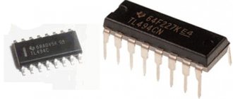
Stabilizers of the LM family
In our article we will look at voltage stabilizers of the LM78XX family. The 78XX series is produced in metal cases TO-3 (left) and in plastic cases TO-220 (right). Such stabilizers have three terminals: input, ground (common) and output.
Instead of “XX”, manufacturers indicate the stabilization voltage that this stabilizer will give us. For example, the 7805 stabilizer will produce 5 Volts at the output, 7812 will produce 12 Volts, and 7815 will produce 15 Volts. Everything is very simple.
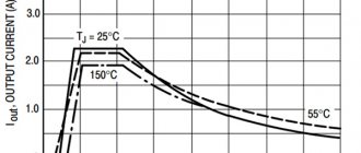
Current accuracy and output voltage
In this case, the instability of the quiescent current is Δ I d = 0.5 mA. This value determines the accuracy of setting the output current. Also, the accuracy of setting the output current value is determined by the accuracy of resistance R*. It is better to use a resistor with an accuracy of no worse than 1%.
A certain convenience here is the fact that the circuit cannot produce a voltage higher than the specified stabilization voltage. For example, when using a 7805 stabilizer, the output voltage cannot exceed 5 volts. This can be critical.
Read also: Color temperature 3000k what color is it
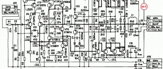
Connection diagram
And here is the connection diagram for such stabilizers. This circuit is suitable for all stabilizers of the 78XX family.
In the diagram we see two capacitors that are sealed on each side. These are the minimum values of capacitors; it is possible, and even desirable, to supply a higher value. This is required to reduce ripple at both the input and output. For those who have forgotten what ripple is, you can look at the article on how to obtain a constant voltage from an alternating voltage.
Vehicle PDF Manual, Wiring Diagrams and DTC Trouble Codes
KIA DTC vehicle fault codes - Rio, Ceed, Sportage, Picanto, Sorento, Cerato, Spectra, Optima, Opirus, Carnival, Magentis, Bongo
KIA Car Manuals PDF & wiring diagrams above page - Stonic, Cadenza, Rio, Sorento, Amanti, Borrego, Optima, Forte, Rondo, Sportage, Sedona, Niro, Spectra, Carnival, Ceed, Pro Ceed, Stinger, Venga ; KIA Passenger cars EWD p.
At the time of its founding, the Korean company was called KyungSung Precision Industry . The main activity of the company was individual cars.
Later, namely on May 15, 1944, a Korean company called KIA . The combination of these three mysterious letters carries the following meaning - the first syllable KI in the word KIA means - to come out into the world. The second syllable A means Asia. Therefore, the meaning of the word KIA is interpreted as an outlet from Asia to the whole world.
The history of KIA Motors begins in 1944. The company produced components for bicycle equipment in a small enterprise located in the modern city of Seoul.
Anticipating the great future of the automobile industry, Koreans have been paying special attention to automobile production since 1960. The first steps were taken from the experience of Japanese manufacturers.
In 1961, the company managed to organize mass production of motorcycles, and the following year the first three-wheeled truck was developed, but its mass production was postponed for a long time. 12 years old.
In 1976, the corporation created several subsidiaries - Kia Service Corp. and Kia Machine Tool Ltd. Subsequent growth is driven by the acquisition of Asia Motors .
KIA is introducing its diesel engine for the first time, and also launches the Peugeot 604 and Fiat 132 .
In 1987, Kia launched the new Pride , which was based on the Mazda 121 .
In 1997, Asia was hit by a severe economic crisis and KIA was unable to cope with it on its own, leading to its bankruptcy. A year later, the bankrupt KIA was purchased by Hyundai Motors .
.
Characteristics of stabilizers
What voltage should be supplied for the stabilizer to work as it should? To do this, we are looking for a datasheet for stabilizers and studying it carefully. We are interested in these characteristics:
Output voltage - output voltage
Input voltage - input voltage
We are looking for our 7805. It gives us an output voltage of 5 Volts. Manufacturers noted a voltage of 10 volts as the desired input voltage. But it happens that the output stabilized voltage is sometimes either slightly underestimated or slightly overestimated.
For electronic trinkets, fractions of volts are not felt, but for precision (accurate) equipment it is better to assemble your own circuits. Here we see that the 7805 stabilizer can give us one of the voltages in the range of 4.75 - 5.25 Volts, but the conditions must be met that the output current in the load will not exceed 1 Ampere. An unstabilized DC voltage can “fluctuate” in the range from 7.5 to 20 Volts, while the output will always be 5 Volts.
The power dissipation on the stabilizer can reach up to 15 Watts - this is a decent value for such a small radio component. Therefore, if the load at the output of such a stabilizer consumes a decent current, I think it’s worth thinking about cooling the stabilizer. To do this, it must be placed on the radiator through KPT paste. The greater the current at the output of the stabilizer, the larger the radiator should be. It would be generally ideal if the radiator was also blown by a fan.
Stabilizer operation in practice
Let's look at our ward, namely the LM7805 stabilizer. As you already understand, at the output we should get 5 Volts of stabilized voltage.
Let's assemble it according to the diagram
We take our Breadboard and quickly assemble the connection diagram suggested above. The two yellow ones are capacitors, although it is not necessary to install them.
So, wires 1,2 - here we drive the unstabilized input DC voltage, remove 5 Volts from wires 3 and 2.
On the Power Supply we set the voltage in the range of 7.5 Volts and up to 20 Volts. In this case, I set the voltage to 8.52 Volts.
And what did we get at the output of this stabilizer? 5.04 Volts! This is the value we will get at the output of this stabilizer if we supply voltage in the range from 7.5 to 20 Volts. Works great!
Let's check one more of our stabilizers. I think you have already guessed how many volts it is.
We assemble it according to the diagram above and measure the input voltage. According to the datasheet, you can supply it with an input voltage from 14.5 to 27 Volts. We set 15 Volts with kopecks.
And here is the output voltage. Damn, some 0.3 Volts is not enough for 12 Volts. For radio equipment operating on 12 Volts this is not critical.
Load resistance
At the same time, it is worth considering the load resistance. For example, if you need to provide 100 mA through a load with a resistance of 100 Ohms, then according to Ohm's law we get the voltage
V= I*R = 0.1 * 100 = 10 Volts
With these simple calculations, we obtained the voltage that needs to be applied to a 100 Ohm load in order to provide it with a current of 100 mA. This means that for this task it is rational to install a 7812 or 7815 stabilizer at 12 volts and 15 volts, respectively, in order to have a reserve.
But it will no longer be possible to provide the same current through a 10 kOhm resistor. This requires a voltage of 100 volts, which these microcircuits can no longer do.
How to make a power supply for 5, 9.12 Volts
How to make a simple and highly stable power supply for 5, 9 or even 12 Volts? Yes, very simple. To do this, you need to read this article and install a stabilizer on the radiator at the output! That's all! The circuit will be approximately like this for a 5 Volt power supply:
Two electrolytic capacitors to eliminate ripple and a highly stable 5 volt power supply at your service! To get a power supply for a higher voltage, we also need to get a higher voltage at the output of the transformer. Aim for the voltage on capacitor C1 to be no less than in the datasheet for the stabilizer being described.
To ensure that the voltage stabilizer does not overheat, apply the minimum voltage specified in the datasheet to the input. For example, for the 7805 stabilizer this voltage is 7.5 Volts, and for the 7812 stabilizer the desired input voltage can be considered a voltage of 14.5 Volts. This is due to the fact that the voltage difference, and therefore the power, the stabilizer will dissipate on itself.
As you remember, the power formula is P=IU, where U is voltage and I is current. Consequently, the higher the input voltage of the stabilizer, the greater the power consumed by it. And excess power means heating. As a result of heating, such a stabilizer may overheat and enter a protection state, in which further operation of the stabilizer stops or even burn out.
Pin assignment and operating principle
According to the principle of operation, all microcircuits in the series belong to linear regulators. This means that the input voltage is distributed between the regulator element (transistor) of the stabilizer and the load so that the voltage drops across the load, which is set by the internal elements of the microcircuit or external circuits.
If the input voltage increases, the transistor closes; if it decreases, it opens slightly so that the output voltage remains constant. When the load current changes, the stabilizer acts in the same way, maintaining the load voltage constant.
This scheme has disadvantages:
- The load current constantly flows through the regulating element, so the power P=Uregulator⋅Iload is constantly dissipated on it. This power is wasted and limits the efficiency of the system - it cannot be higher than Uload/Uregulator.
- The input voltage must exceed the stabilization voltage.
But the ease of use and low cost of the device outweigh the disadvantages, and in the range of operating currents up to 3 A (and even higher), it makes no sense to use anything more complex.
For voltage regulators with a fixed voltage, as well as for adjustable stabilizers of new developments (K142EN12, K142EN18) in three- and four-pin versions, the pins are designated by the numbers 17,8,2. This illogical combination was obviously chosen to match the pins with microcircuits in DIP packages. In fact, such “dense” markings are preserved only in technical documentation, and on the diagrams they use terminal designations corresponding to foreign analogues.