In multi-band speaker systems, in addition to the speakers, frequency filters must be installed. This is necessary to divide the sound band depending on the type of speaker. All speakers can be divided into the following groups:
- Low frequency
- Midrange
- High frequency
- Broadband
The simplest acoustic systems, consisting of one full-range speaker, do not have filters, but the playback range of such a system is small. It can be 40-50 Hz – 12-16 kHz. Good speaker systems include three speakers with the signal coming from the amplifier divided into the following three bands:
- LF – 20 Hz-500 Hz
- MF – 200 Hz-7000 Hz
- HF – 2000 Hz-22000 Hz
The audio signal is divided into separate bands using passive LC filters. Connecting HF speakers through a capacitor is associated with the need to limit power at frequencies determined by the capacitance of the capacitor. The fact is that high-frequency tweeters are small in size and, accordingly, have a small diffuser made of hard material. High bass power may damage the tweeter driver. In addition, the “low frequencies” reproduced by the tweeter will sound with strong distortion, disrupting the entire sound picture.
How do you know if there are beepers?
You come up and cover the beeper with your palm .
. If nothing has changed, she remains silent. — Left speaker: The tweeter is definitely silent.
Interesting materials:
How to get all apps back on Windows 10? How to return Windows 8 back 1 day? How to return Windows 8 from Windows 10? How to restore factory settings on a Windows 10 laptop? How to restore sound on a Windows 10 laptop? How to go back to a previous Windows 10 update? How to go back to a Windows 10 backup? How to see invisible folders in Windows 7? How to see file extensions in Windows 7? How to see hidden folders in Windows 8?
Speaker cuts with capacitor
Selecting the capacitance of the capacitor for speaker cutting
Introduction
When buying speakers and connecting them without a processor, or without an amplifier, do not rush into choosing a capacitor.
Here's an example:
Let's take two 4 Ohm tweeters and measure the impedance, say at a cutoff frequency of 5 kHz, then in fact it may turn out that one tweeter at this frequency has an impedance of 5 Ohms and the other has 7 Ohms. According to the table below, we are trying to cut them at 5 kHz with an 8 µF capacitor. As a result, the first one will be cut at 4 kHz, and the second with the same capacitor will be cut at 3 kHz. The result is that the first one will simply make a terrible sound, the second one will start to burn.
Speaker cut table
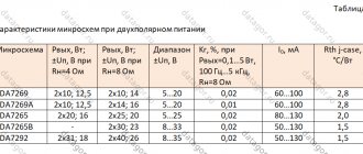
| Speaker cutoff frequency | High Pass Filter (HPF) | Note | |
| 4 ohm | 8 ohm | ||
| 50 Hz | 796.7 µF | 398.1 µF | — |
| 75 Hz | 530.8 µF | 265.4 µF | — |
| 100 Hz | 398.1 µF | 199 µF | — |
| 125 Hz | 318.5 µF | 159.2 µF | — |
| 150 Hz | 258.4 µF | 132.7 µF | Minimum value for midrange speakers |
| 175 Hz | 227.5 µF | 113.7 µF | — |
| 200 Hz | 199 µF | 99.5 µF | — |
| 225 Hz | 176.9 µF | 88.5 µF | — |
| 250 Hz | 159.2 µF | 79.1 µF | Minimum value for neodymium midrange speakers |
| 275 Hz | 144.8 µF | 72.4 µF | — |
| 300 Hz | 132.7 µF | 66.3 µF | — |
| 400 Hz | 99.5 µF | 49.8 µF | — |
| 500 Hz | 79.6 µF | 39.8 µF | — |
| 600 Hz | 66.3 µF | 33.2 µF | — |
| 700 Hz | 56.9 µF | 28.4 µF | — |
| 900 Hz | 44.2 µF | 22.1 µF | — |
| 1000 Hz | 39.8 µF | 19.9 µF | — |
| 1100 Hz | 36.2 µF | 18.1 µF | — |
| 1200 Hz | 33.2 µF | 16.6 µF | — |
| 1300 Hz | 30.6 µF | 15.3 µF | — |
| 1400 Hz | 28.4 µF | 14.2 µF | — |
| 1500 Hz | 26.5 µF | 13.3 µF | — |
| 1600 Hz | 24.9 µF | 12.4 µF | — |
| 1700 Hz | 23.4 µF | 11.7 µF | — |
| 1800 Hz | 22.1 µF | 11.1 µF | — |
| 1900 Hz | 21 µF | 10.5 µF | — |
| 2000 Hz | 19.9 µF | 9.9 µF | — |
| 3000 Hz | 13.3 µF | 6.6 µF | Minimum value for silk tweeters |
| 4000 Hz | 10 µF | 5 µF | — |
| 5000 Hz | 8 µF | 4 µF | — |
| 6000 Hz | 6.6 µF | 3.3 µF | Minimum value for loud horn tweeters |
| 7000 Hz | 5.7 µF | 2.8 µF | — |
| 8000 Hz | 5 µF | 2.5 µF | Minimum value for loud horn tweeters considering wide midrange range |
| 9000 Hz | 4.4 µF | 2.2 µF | — |
| 10000 Hz | 4 µF | 2 µF | — |
| Before choosing, we recommend measuring the impedance of the speakers with a multi-meter. The capacitance rating of the capacitor is indicated on its body. | |||
Conclusion
If you do everything according to tables and trust the values without using your head, you will get bad sound and a lot of burned-out speakers.
- Install only non-polar capacitors.
- Do not install electrolytic capacitors. In most cases, they are installed on cheap Chinese speakers.
- Buy capacitors of different capacities. The larger the capacity, the lower it will cut your squeaker.
- Solder the capacitor closer to the terminal. In this case, it does not matter at all which terminal the capacitor will hang on. But if you started soldering to the positive terminal, then hang it on the positive terminals on all other tweeters.
IMPORTANT!
The speaker cut according to the recommendation does not give accurate values.
WHY IS LOW FREQUENCY BASS SO HARD TO STOP?
Before you start implementing ways to get rid of bass noise, you need to understand what it is. Essentially, bass is a kind of physical manifestation of sound. Of course, this is an important part of the hearing experience. Even hard of hearing and deaf people can feel bass as a physical sensation. And since we can't hear it technically, getting rid of the bass can be a little more difficult than just using conventional soundproofing methods.
When soundproofing against high-frequency sound waves, you must use materials with high mass and density. Of course, high-density fabrics are great for sound absorption and redistribution. However, materials with a lot of mass completely block sound waves and even the type of sensation that bass produces. So when you're looking for effective bass-blocking materials, you'll want to stick with something with a lot of mass.
Low frequencies can travel through brick and concrete, which is why you sometimes feel vibrations when a heavy truck passes in front of your building. This sensation is caused by structural noise, which is when sound travels through your walls, ceilings, and floors rather than through the air. You still need to find a way to reduce the level of bass noise reaching your home. Luckily, I've put together this handy list of ways to deal with it right here.
Probably, many of you, if you need to record sound from several microphones or radio systems at once, do the following: connect one audio source to the camera, and the second to the audio recorder. This option is good for everyone, but it forces you to carry a recorder with you, and then sync the video with the audio in editing, which takes extra time, even if you use PluralEyes.
If your camera only has one audio input, a 3.5 mm stereo mini jack, then you might be tempted to buy something like this and just mix the 2 signals.
The disadvantage of this solution is quite obvious: you cannot separately control the sound from the microphones during editing. And, of course, if you have a defective sound in one of the microphones, then the sound from the other microphone will also turn into defective. In addition, with this configuration you need to carefully configure the sound from the radio systems before shooting. Those. If one person is speaking softly and another is speaking loudly, then you need to anticipate all of this and place the lavalier microphones at different distances from their mouths. In general, in professional work this option is not acceptable in principle.
But we can solder the signal mixer ourselves from two stereo mini jacks to one so that the sound from one radio system goes to the left channel, and from the other to the right. This will allow us to independently control channels during editing and turn off/mute a microphone we don’t need and apply individual settings for the equalizer, compressor, etc.
As you can imagine, the sound in radio systems with a single lavalier microphone is monophonic, and the stereo output of the receiver simply sends the same signal to the left and right channels. Making an adapter is not difficult:
Those who have 2 full XLR inputs on their video camera are luckier, because... they can adjust audio levels separately in each channel directly on the camera. To connect mini jack to XLR, just solder a simple adapter:
For example, here's how I did it:
Now, as for editing the material in Adobe Premiere Pro.
In order for the sound of each radio system to be heard in both the left and right speakers, it is necessary to create 2 identical audio tracks:
Next, you need to configure the supply of channel L to L+R in the first track and the supply of channel R to L+R on the second track.
Now for each track corresponding to one of the radio systems, we can set individual settings.
As you can see, it’s nothing complicated, so you don’t have to take an audio recorder with you anymore. Moreover, you can monitor the sound from both radio systems using headphones connected directly to the camera.
A list of all the equipment we used to shoot wedding videos is here.
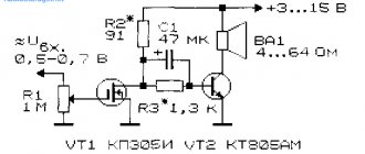
How to connect a tweeter through a capacitor
The RF head connection circuit, consisting of only one capacitor, is called a filter or first-order passive crossover. It's called "High-passfilter" and works like this. The capacitance of the capacitor determines the cutoff band. This does not mean that audio frequencies below the cutoff level will not be reproduced by the tweeter. A first-order crossover has a sensitivity of 6 dB (decibels) per octave. An octave is two times less or more. If the cutoff value is 2,000 Hertz, then a frequency lying an octave lower, that is, 1,000 Hertz will be reproduced with a level 6 dB less, a decrease in level by 500 Hertz will be 12 dB, and so on.
Based on the size and rigidity of the high-frequency loudspeaker cone, we can assume that low frequencies will not have a significant effect on the reproduction of the high-frequency range. There are more complex second-order crossovers, the circuit of which, in addition to the capacitor, includes a choke. They provide a power cut of 12 decibels per octave, and third-order filters provide a roll-off of 18 decibels per octave.
Equalizer
An equalizer allows you to make the sound more even - raise or lower the bass, mid and high frequencies. This is a rather fine adjustment of the audio system. It is not the entire sound range that is regulated at once, as in other menu items, but specific frequency bands. Different models have different numbers of them, depending on the class of equipment. There are five of them in Pioneer radios: 80 Hz, 250 Hz, 800 Hz, 2.5 kHz and 8 kHz.
The equalizer is located in the “Audio” section of the settings menu, EQ item. In it you can select one of the preset standard settings. For those who are not satisfied with these options, there are two sets of user settings (Custom). You can switch between them both from the menu and the EQ button next to the joystick. To make changes to frequency parameters in a custom setting, you need to select it with the wheel and press the joystick. Then turn the wheel to select one of the equalizer frequency bands. Press the joystick again and set the position from -6 (attenuate frequency) to +6 (increase). By doing this you can make some frequencies louder and others quieter.
There is no universal recipe for setting the equalizer on the radio. It is performed by ear depending on the preferences of the consumer. In addition, different adjustment options are selected for a specific genre of music.
We can only give rough recommendations:
- if heavy music is played, it is worth increasing the bass - 80 Hz (but not too much, +2–+3 is enough). Percussion instruments sound around 250 Hz;
- for music with vocals, frequencies of approximately 250-800+ Hz are needed (male voices are lower, female voices are higher);
- for electronic music you will need high frequencies - 2.5-5 kHz.
Setting the equalizer is a very important step. Using this tool, you can improve the sound quality many times over. Even if the acoustics are not very expensive and of high quality.
How to tame high frequencies in DALI Spektor 2 and place the stage outside the speakers?
Hello!
Where do I start with this?
I bought myself a DALI Spektor 2 speaker, bought a Denon PMA 520AE amplifier for it, I have an EMU 1212m card in my PC, I only listen to Flac.
In principle, the sound is good, dynamic, with elastic bass, does not drone or hum, the middle is a little clogged due to the preponderance of high frequencies, but still plays lively and in detail, various techno and electronic music plays well, pop music is good, various calm music is not bad. But classical, instrumental, where the stage is important, the arrangement and naturalness of sound instruments, this is where the problems begin, in the sound stage there is no precise arrangement of sound instruments, something plays to the right, something to the left, the depth is almost not felt, everything plays approximately on the same plane. But what’s most annoying is that some sound “effects” sound from the speakers themselves, that is, not somewhere out there in space, but simply from the box itself. Well, of course, the high frequencies are a little annoying, I seem to have gotten used to it, but these ssss-s-s-s-s-s-s-s-s-s-s-s-s-sounds can be tiring.
I tried to listen from the built-in sound card, the same situation, but less pronounced due to the general deterioration of the sound, I tried connecting my old Sony Hi-Fi music center instead of a Denon amplifier, the same situation, except the bass became more confident (probably from 80 Watts of power) . In general, the sound from Sony is in no way inferior to the Denon 520AE.
I’ve been listening to acoustics for the fifth month now, as if the warm-up had passed, and my ears should have gotten used to it, in short, there is a desire to change the speakers, or hope for a more expensive amplifier.
I have some experience of listening to Hi-Fi systems, once upon a time I had Dynaudio DM 2/6 + NAD 326 BEE + ASUS Xonar STX, a very wide stage with a very precise placement of sound instruments, sometimes the sound was striking in its scale and assertiveness, it sometimes seemed that the speakers were about to burst, the sound was very natural. BUT.., it’s very monitory, at first you sit there like WOW, and then after an hour the wow goes away and you start to get tired, it’s like watching a movie entirely consisting of special effects, it seems cool, but it gets boring. I listened to it for a few months and sold it, it’s good that I bought it used.
Then I once listened to the Mission MX1 in the salon, and I really liked its sound, how is it similar in character to Dynaudio, is the sound a little simpler? but more exciting, I played Mission with a Denon PMA-300V, later for financial reasons I sold all my Hi-Fi.
And after 3 years, I wanted to return to the world of Hi-Fi, and based on laudatory reviews and reviews, I bought a Dali Spektor 2, because I couldn’t find the Mission MX1 on sale at all, and I was hoping that the famous Dali would conquer me.
I would like to ask if anyone listens to these speakers, or is familiar with such a sound feature as the Dali Spektor 2. The main problem is how to remove these high-frequency sounds from the speakers themselves, and how to reduce the high frequencies? Maybe you need a more expensive and powerful amplifier or is this the style of these speakers?
Reducing the resonant frequency of the heads
The lower limit of the frequency range reproduced by the loudspeaker is determined by the main resonant frequency of the head. Unfortunately, there are very rarely heads on sale that have a main resonant frequency below 60-80 Hz. Therefore, to expand the range of operating frequencies of acoustic systems, it seems very relevant to reduce the main resonant frequency of the heads used in them. As is known, the moving head system (diffuser with voice coil) in the main resonance region is a simple oscillatory system consisting of mass and flexibility of the suspension. The resonant frequency of such a system is determined by the formula:
where m is the mass of the diffuser, voice coil and attached air mass, g; C - suspension flexibility, cm/din.
Thus, in order to reduce the main resonant frequency of the head, it is necessary to increase either the mass of the diffuser and voice coil, or the flexibility of their suspension, or both. The easiest way is to increase the mass of the diffuser by attaching additional weight to it. However, increasing the mass of the moving head system is unprofitable, since this will reduce not only the resonant frequency, but also the sound pressure created by the head. The fact is that the force F created by the current I in the voice coil of the dynamic head is equal to
F=B*l*I, where B is the magnetic induction in the gap; l is the length of the voice coil conductor.
On the other hand, according to the laws of mechanics, this force is equal to
F=m*a, where m is the mass of the moving system; a is oscillatory acceleration.
Since the force applied to the voice coil depends for a given head only on the current value, by increasing the mass, we will reduce the oscillatory acceleration of the coil and diffuser by the same amount; and since the sound pressure generated by the head in this frequency region is proportional to the acceleration of the cone, a decrease in acceleration is equivalent to a decrease in sound pressure. If we tried to halve the main resonant frequency of the head, this would require increasing the mass of the moving system by four times, and the sound pressure created by the head would decrease by the same amount at a constant current in the coil. In addition, an increase in mass would increase the quality factor of the moving system and increase the resonant peak, and with it the unevenness of the frequency response, which, in turn, would worsen the transient characteristics of the loudspeaker.
Therefore, to reduce the resonant frequency of the head, it is more expedient to increase the flexibility of the diffuser suspension and the centering disk, that is, to reduce the rigidity of the moving system. This is done as follows. First of all, peel off or cut off the diffuser collar with a sharp scalpel or blade (along the diffuser holder ring). Then the flexible leads of the voice coil are unsoldered, the ring of the centering disk and the getinaks “spider” (if any) are unscrewed, or the centering disk is peeled off from the diffuser holder.
The flexibility of the centering disk with corrugations is increased by cutting three or four cone-shaped holes in it evenly around the circumference (see Fig. 1). The total area of these holes should be 0.4-0.5 times the area of the centering disk corrugations. To protect the magnetic gap from dust, gauze is glued to the cutouts or the entire disk using ordinary rubber glue or BF-6 glue. If the voice coil is centered with a getinax (textolite) “spider,” then flexibility is increased by reducing the width of its arms (by filing them with a file or carefully biting them with wire cutters). After this, part of the edge corrugation at the diffuser is cut off so that there is a gap of about 200 mm between the edge of the diffuser and the diffuser holder ring. If at the same time there is a corrugation on the edge of the diffuser, then it is straightened to a length of about 10 mm and a suspension in the form of arms made of povinol or soft textile is glued to it. To increase flexibility, the textile or knit backing should be removed if possible.
Very flexible and elastic arms can be made using silicone glue - "Elastosil" sealant from thin nylon stockings. The top of the stocking is cut lengthwise and markings are made on the resulting fabric 24-28 cm wide (see Fig. 2). When marking, the arches should be located across the stocking (see Fig. 2), since the elasticity of the stocking is greater in the longitudinal direction. Then, placing a piece of smooth plastic film on some board or thick cardboard, put stocking fabric on it and secure it along the edges with buttons or nails. After this, “Elastosil” is applied to the knitwear with a spatula or the end of a metal ruler, so that the threads of the knitwear are not visible. After a day (the polymerization time of “elastosil”), the knitwear is turned over and “elastosil” is applied to the other side.
To cut out the arms, make a cardboard template. It is advisable to hang the diffuser on no more than three or four arms so that each arm occupies a third or a quarter of the circumference of the diffuser, respectively. On the arms and on the edge of the diffuser, mark with a pencil the surfaces with which they should be glued; the width of these surfaces should be 7-10 mm. The finished arms are smeared one by one with glue and glued to the marked edge of the diffuser with “elastosil” or silicone glue KT-30 or MSN-7. Arches made of pavinol or textile are glued to the surface where the textile was located using BF-2, 88 or AB-4 glue. It is recommended to first check the suitability (compliance) of the glue with the material by gluing a piece of material to thick paper.
The joints between the arms should also be glued so that there are no gaps. It is best to do this with “elastosil”; for pavinol or text vinyl temples, it is recommended to fasten the edges with threads and fill them in several stages with ordinary rubber glue.
Having finished hanging the diffuser, it is installed in the diffuser holder so that the voice coil fits into the gap. Then the ring of the centering disk is strengthened and the voice coil is pre-centered (before gluing the suspension). Next, the diffuser suspension arms are glued one by one to the diffuser holder ring. To bend the arms,
When applying glue to the diffuser holder ring, it is convenient to use alligator clips with single-pole plugs inserted into them (for weight). After gluing the suspension, the final alignment of the voice coil is carried out and the rings of the centering disk or getinax “spider” are secured. If the centering disk does not have a metal ring and is peeled off, then first glue the diffuser suspension, and then the centering disk, while simultaneously centering the voice coil in the gap. Lastly, the voice coil leads are soldered and support arms made of cardboard, sponge rubber or felt are glued to the diffuser holder.
If the diffuser has a crack (break), then it is best to seal it with “elastosil” glue or fill it in several stages with rubber glue.
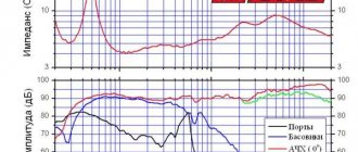
Using the described method, it is possible to reduce the frequency of the main resonance of the head by 1.5-2 times. For example in Fig. Figure 3 shows the frequency characteristics of the impedance of the 4A-18 head before (dotted line) and after the modification.
This head was manufactured by the Leningrad film equipment plant "Kinap" in 1954; its alteration consisted of cutting three windows in the centering disk and replacing the edge corrugation with pavinol arches, and the textile backing was not removed. The resonant frequency decreased from 105 Hz to 70 Hz, that is, by 1.5 times. It is interesting to note that the same decrease in the resonance frequency gives an additional weight of 25 g.
(Radio 3/75)
Low pass filter (subwoofer)
After we have dealt with the speakers, we will configure the radio for the subwoofer. For this we need a low pass filter. With its help, we match the frequencies of the speakers and subwoofer.
The situation looks like this. When we removed the bass from the speakers (set HPF to 80+), we got loud and high-quality sound. The next step is to “dock” the subwoofer to our speakers. To do this, go to the menu, select the audio item, and in it we find the subwoofer control section.
There are three meanings here:
- The first number is the cutoff frequency of the subwoofer. Everything here is the same as with the equalizer. There are simply no specific settings, and the range in which you can “play around” is from 63 to 100 Hz.
- The next number is the volume of our subwoofer. We think everything is simple here, you can make the subwoofer louder or quieter relative to the acoustics, the scale is from -6 to +6.
- The next figure is the frequency attenuation slope. Just like in HPF, it can be either 12 or 24. There is also a little advice here: if you set a high cut, then set the slope to 24, if lower, then you can set it to 12 or 24.
The sound quality depends not only on the settings of your audio system, but also on what speakers you have installed. If you want to replace them, we recommend that you read the article “what you need to know when choosing car speakers”
Never hear that bass again
The most important and effective tips for getting rid of low-frequency noise have been presented at the beginning of the list. After all, most people don't really want to be an annoying loud neighbor. Your neighbor may not even realize how loud they are. This is why talking to them may be the best option.
However, your neighbor may be unwilling or unable to take soundproofing measures. In this case, it is best to separate the interior drywall wall from the building structure. Just be sure to do the same with the floor and ceiling if you want the best bass blocking possible.
And, if for some reason you can't change the layout of your apartment, you can always try some of the permanent solutions like white noise or headphones.