The proposed project can be called “Returning to the published”, since it is a continuation of the article Stereo audio amplifier on the TDA2616 chip [1].
During the discussion on Datagore, this publication was emotionally considered as global problems such as: “why are certain room sizes given if you could turn to the ancient Greeks?” and “I don’t want to get old!”, and a specific question: “what can you say about the TDA7265 and TDA7269 microcircuits, used in high-quality music centers and stereo television receivers?” Unable to influence the laws of nature, I will try to highlight a specific issue.
↑ Let's look at the datasheets
Having analyzed the range of microcircuits produced by ST Microelectronics, I identified three completely interchangeable microcircuits in the Multiwatt11 package: TDA7269, TDA7265 and TDA7292.
You can find many variations of datasheets for all these chips on the Internet (see links below). Powerful two-channel Hi-Fi amplifiers are designed for high-quality stereo equipment, stereo systems and Hi-Fi TVs. They have a wide supply voltage range, bipolar power supply, mute mode, standby mode, short circuit and overheat protection.
I purchased two of the indicated microcircuits, ordered the third from the store, and have only tested the TDA7265 in operation so far.
The characteristics of microcircuits with bipolar power supply are given in table. 1, and the assignment of the pins is in table. 2.
Please note that the developers do not provide the output power values of the TDA7265B microcircuit with load resistance Rн=4 Ohm. I assume that you need to focus on the corresponding parameters of the microcircuit without an index.
Depending on the type of microcircuit, the output peak current is 4...5.5 A. The shutdown temperature for overheating is 145°C.
The rate of rise of the output voltage is VUout = 10 V/µs, the gain with an open negative feedback loop is KU0 = 80 dB. Input resistance in non-inverting connection Rin = 20 kOhm.
↑ Let's look at the chip body
There are two microcircuits: one TDA2822, the other with the index “M” - TDA2822M. The integrated circuit TDA2822
(Philips) is designed to create simple audio power amplifiers.
The permissible range of supply voltages is 3…15 V; at Upit=6 V, Rн=4 Ohm, the output power is up to 0.65 W per channel, in the frequency band 30 Hz...18 kHz. The chip package is Powerdip 16. The TDA2822M chip
is made in a different Minidip 8 package and has a different pinout with a slightly lower maximum power dissipation (1 W versus 1.25 W for the TDA2822).
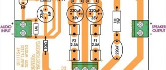
↑ Schematic diagram of the amplifier
The test circuit for connecting microcircuits from the datasheet is practically suitable for “combat” use (Fig. 1).
Rice.
1. Circuit diagram for connecting microcircuits when powered from a bipolar source
In the real scheme (Fig. 2), we will use the recommendations set out in publication [1].
Rice. 2.
Amplifier circuit diagram
Gain
with closed loop feedback KU=1+R7/R5=1+R8/R6=33.26 (30.4 dB).
The output power is determined by the type of chip used and the load resistance (see Table 1).
The microcircuit is controlled by applying the appropriate voltages to pin 5 (Mute/Stand-by) of the DA1 microcircuit.
The Play operating mode is implemented at a voltage less than +Up-6. For example, for a supply voltage of ±20 V, Play mode is provided when the voltage at pin 5 of the microcircuit is from 0 to 14 V.
For the Mute mute mode, it is enough to apply a voltage in the range from + Up-6 to + Up-2.5 (from 14 V to 17.5 V).
The microcircuit enters Stand-by mode at a voltage greater than +Up-2.5 (in our example from 17.5 V to 20 V).
The control circuit on transistor VT1 is necessary for development when implementing microprocessor control. For a always-on microcircuit (Play mode), it is enough to connect pin 5 of the microcircuit to the common wire.
Depending on the position of jumpers P1 and P2, the control circuit provides a voltage at pin 5 equal to 11.5 V in Play mode; 16.1 V in Mute mode and about 20 V in Stand-by mode.
To reduce electrolytic distortions, the capacitance of capacitors C1, C2 is doubled compared to a typical connection circuit.
To suppress radio frequency interference, input passive low-pass filters R3, C3 and R4, C4 have been added.
In order to prevent self-excitation of the UMZCH with and without a complex load, Zobel circuits R9, C9 and R10, C10 are included.
Circuit design of a single-board stereo headphone amplifier based on the TDA2822 chip
Let's look again at the amplifier board vertically from above:
With the exception of the input circuit, the board corresponds to the typical circuit shown in the datasheet:
As for the input circuit, it includes a variable volume control resistor with a nominal value of 50K; and behind it come voltage dividers consisting of resistors 22K 1% and 1.5K 1%.
In total, the division coefficient is (22+1.5)/1.5 = 15.67.
Accordingly, the gain of the entire board at the maximum position of the volume control will be 89.12/15.67 = 5.69; where 89.12 is the gain of the microcircuit itself (39 dB, converted to “folds”).
During testing, the calculated gain was confirmed with good accuracy.
Let's return to the input circuit.
The value of the electrolytic capacitors connected to pins 5 and 8 of the microcircuit is 10 μF (and not 100, as indicated in the diagram; but this is acceptable here).
The rating of the power supply blocking capacitor is 470 µF * 16 V, which we fully approve of.
At the output, RC circuits C6R3 and C7R4 serve to prevent self-excitation of the amplifier.
Here, in fact, is the whole scheme.
There is also an option in the datasheet to enable this two-channel microcircuit in single-channel bridge amplifier mode (for a stereo amplifier, two microcircuits will be required).
But such a circuit is not suitable for working with standard headphones with three wires (common ground); it can only work with independent speaker connections.
Important note: the board does not have a “foolproof” diode in the power circuit, and therefore the polarity of the power supply should never be reversed!!!
↑ Details, printed circuit board and characteristics of UMZCH
Amplifier parts
DA1 - TDA7265 STM, Multiwatt 11 case (replacement: TDA7269, TDA7269A, TDA7265B, TDA7292) - 1 pc., VT1 - 2N2222 - 1 pc., VD1 - Zener diode BZX55C5V1 5.1V 0.4W, DO-35 case - 1 pc. ., R1, R2 - Res.-0.25-1.0 MOhm (brown, black, green, gold) - 2 pcs., R3 - R6 - Res.-0.25-620 Ohm (blue, red, brown , golden) or res.-0.25-619 Ohm 0.5% (blue, brown, white, black, green) - 4 pcs., R7, R8 - Res.-0.25-20 kOhm (red, black , orange, golden) or res.-0.25-20 kOhm 0.5% (red, black, black, red, green) - 2 pcs., R9, R10 - Res.-2-4.7 Ohm (yellow , purple, golden, golden) - 2 pcs., R11 - Res.-0.25-2 kOhm (red, black, red, golden) - 1 pc., R12, R13 - Res.-0.25-15 kOhm (brown, green, orange, golden) - 2 pcs., R14 - Res.-0.25-18 kOhm (brown, grey, orange, golden) - 1 pc., C1, C2 - Cond. 2.2/50V 0511 NPL or cond. K73-17 imp. 2.2 µF x 100 V 5% POLYESTER BOXED, B32522C1225C1225J000 - 2 pcs., C3, C4 - Cond. NPO 750 pF 5% ceramic. imp. or FKP2 750 pF x 100 V, WIMA - 2 pcs., C5, C6, C9, C10 - Cond. K73-17 imp., 0.1 µF, 63V, 10%, POLYESTER BOXED, B32529C0104K000 - 4 pcs., C7, C8 - Cond. 1000/50V 1331+105°C - 2 pcs., C11 - Cond. 1/50V 0405+85°C - 1 pc., X1, X2 X3; X4, X5, X6 - TB-3 (300) terminal block 3 pins, pitch 5 mm per board - 2 pcs., X7, X8; X9, X10 - TB-01A terminal block 2 pins, pitch 5 mm per board - 2 pcs., J1, J2 - PLS-3 2.54 plug 3 pins per board - 2 pcs., P1, P2 - MJ-0- 4 removable jumpers with a pitch of 2.54 mm and a height of 4.5 mm for PLS pin contacts - 2 pcs., printed circuit board 82x82 mm - 1 pc.
Instead of the 2N2222 transistor indicated in the diagram, you can use transistors KSP2222, BC546, as well as domestic KT3102A, KT3102B.
Hobbyists planning to “get the most out of the circuit” can use film capacitors K73-17, WIMA instead of non-polar capacitors C1, C2 and ceramic capacitors C3, C4. In this case, the printed circuit board will have to be adjusted.
To obtain identical transmission coefficients for each channel, resistors R5, R6 and R7, R8 must be selected in pairs with a deviation from the values indicated in the diagram of no more than 0.5...1%.
The three-pin PLS plug can be cut from a long PLS-40 or PLS-80 having the required 2.54mm pitch.
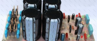
All parts of the UMZCH are mounted on a printed circuit board (see Fig. 3), made of foiled fiberglass laminate 2 mm thick. The DA1 chip is installed on a heat sink with a cooling surface area of about 380 square meters. cm.
Rice. 3.
Placing parts of a stereo amplifier on a printed circuit board. Paths are shown in clear light
The power supply is borrowed from the previous design [1, fig. 3]. A power transformer with a power of 50 W and a voltage on the secondary windings of 2×12 V for Rн=4 Ohm and 2×15 V for Rн=8 Ohm is required.
The following characteristics were obtained:
Maximum output power: Rn=8 Ohm - 25 W, Rn=4 Ohm - 20 W; Level bandwidth - 3 dB: 4 Hz...100 kHz; Input voltage: 0.4V; Input impedance: 20 kOhm; Harmonic distortion: 0.02%; Separation between channels: no worse than 70 dB.
Appearance and design of a single-board 2-channel class AB amplifier based on the TDA2822 chip
Let's look at the amplifier board from different angles (click to enlarge, opens in a new window):
As you can see, the kit even includes a knob for the variable volume resistor.
The input signal is supplied through a socket for a three-pin connector - a 3.5 mm jack.
Next angle:
All external connections, except for the input audio signal, are made without soldering - using screw terminal blocks, which is very convenient.
Next is the top view:
Here you can see that there are really very few details.
And even here, four details are not entirely mandatory; These are two resistor dividers that are installed immediately after the volume control.
A special feature of the mechanical design is the presence of only one screw hole for securing the board. But this is already from the “better than nothing” series.
Another top view - under “sliding” lighting, so that the chip markings can be seen:
Reverse side of the board:
In the next chapter we’ll look at what’s what and why on this amplifier board.
↑ Sources mentioned
• Stereo audio amplifier on TDA2616 chip • Audio amplifier TDA7265 2×25W.
Object “Pipe” - the answer • TDA7265 Information sheet on Datagor. • TDA7265 (25 +25W STEREO AMPLIFIER WITH MUTE & ST-BY, April 2002). • TDA7265B (30 W + 30 W stereo amplifier with mute and standby, December 2011). • TDA7269A (14W+14W STEREO AMPLIFIER WITH MUTE & ST-BY, June 2003). • TDA7292 (40 W + 40 W stereo amplifier with mute and standby, February 2012). • Bashirov S. R., Bashirov A. S. Modern integrated amplifiers. - M.: EKSMO, 2008. - 176 p. • Avramenko Yu. F. High-quality sound is easy today. - K.: MK-Press, 2007. - 288 p. Thank you for your attention!
↑ Experiments with a stereo amplifier
were carried out in accordance with the schemes shown in Fig.
3 and 8. The stereo amplifier shown in Fig. 3, can be used with both small speaker systems and headphones. Briefly about the purpose of the elements.
Resistors R1 and R2 determine the input impedance of the amplifier. Capacitors C1, C2 in the OOS circuit are connected in series with resistors R5, R6, which make it possible to reduce the gain in each of the amplifier channels within small limits. As mentioned above, the resistance of resistors R5, R6 can be in the range of 100...240 Ohms.
Since there is a constant voltage at the outputs of the UMZCH, approximately equal to half the voltage of the power source, the connection to the load is made through isolation capacitors C3, C4.
At the output of each channel, Zobel circuits R3, C6 and R4, C7 are included, ensuring stable operation of the amplifier. By the way, without these circuits the amplifier is inoperable.
Two capacitors are installed along the power supply circuit of the amplifier: ceramic C8 and oxide C5.
Fragment excluded. The full version is available to patrons and full members of the community.
Rice. 3. Schematic diagram of an experimental stereo amplifier
The amplifier has the following characteristics:
Supply voltage Up=1.8…12 V Output voltage Uout=2…4 V Current consumption in quiescent mode Io=6…12 mA Output power Pout=0.45…1.7 W Gain Ku=36…41 (39 ) dB Input impedance Rin=9.0 kOhm Crosstalk attenuation between channels 50 dB.
From a practical point of view, for reliable operation of the amplifier, it is advisable to set the supply voltage to no more than 9 V; in this case, for a load Rн=8 Ohm the output power will be 2x1.0 W, for Rн=16 Ohm - 2x0.6 W and for Rн=32 Ohm - 2x0.3 W. With load resistance Rн=4 Ohm, the optimal supply voltage will be up to 6 V (Pout=2x0.65 W).
The gain of the microcircuit of 39 dB, even taking into account a small downward adjustment by resistors R5, R6, turns out to be excessive for modern signal sources with a voltage of 250...750 mV. For example, for Up=9 V, Rн=8 Ohm, the sensitivity from the input is about 30 mV.
In Fig. 4, a shows the amplifier connection circuit, which allows you to connect a personal computer, MP3 player or radio receiver with a signal level of about 350 mV. For devices with an output signal of 250 mV, the resistance of resistors R1, R2 must be reduced to 33 kOhm; at an output signal level of 0.5 V, resistors R1=R2=68 kOhm, 0.75 V – 110 kOhm should be installed.
Double resistor R3 sets the required volume level. Capacitors C1, C2 are transitional.
Fragment excluded. The full version is available to patrons and full members of the community.
Rice. 4. UMZCH connection diagram: a) - to speaker systems, b) - to headphones (headphones)
In Fig. 4, b shows the connection to the amplifier of the headphone jack. Resistors R4, R5 eliminate clicks when connecting stereo phones, resistors R6, R7 limit the volume level.
During the experiments, I tried to power the UMZCH both from a stabilized power supply (on an LM317 integrated circuit and a BD912 transistor), Fig. 5, and from a battery with a capacity of 7.2 A•h for a voltage of 12 V with a power supply for fixed voltages, Fig. 6.
The supply voltage is supplied by as short a pair of wires as possible, twisted together. A correctly assembled device does not require adjustment.
Fragment excluded. The full version is available to patrons and full members of the community.
Rice. 5. Schematic diagram of a stabilized power supply
Fragment excluded. The full version is available to patrons and full members of the community.
Rice. 6. Rechargeable battery - laboratory power source
A subjective assessment of the noise level showed that when the volume control is set to the maximum level, the noise is barely noticeable. Subjective assessment of sound reproduction quality was made without comparison with the standard. The result is a good sound, listening to soundtracks does not cause irritation.
I checked the chip forums on the Internet, where I came across many messages about searching for unknown sources of noise, self-excitation and other troubles. As a result, he developed a printed circuit board, the distinctive feature of which is the “star” grounding of the elements. A photo view of the printed circuit board from the Sprint-Layout program is shown in Fig. 7.
Fragment excluded. The full version is available to patrons and full members of the community.
Rice. 7. Placement of parts on the experimental printed circuit board
During experiments on this signet, it was not possible to encounter any of the artifacts described on the forums.
Details of the stereo UMZCH on the TDA2822M chip
The printed circuit board is designed for installation of the most common parts: MLT, S2-33, S1-4 or imported resistors with a power of 0.125 or 0.25 W, film capacitors K73-17, K73-24 or imported MKT, imported oxide capacitors.
I used inexpensive but reliable electrolytic capacitors with low impedance, long service life (5000 hours) and the ability to operate at temperatures up to +105°C from Hitano ESX, EHR and EXR series. It should be remembered that the larger the outer diameter of the capacitor in the series, the longer its service life.
The DA1 chip is installed in an eight-pin socket. The TDA2822M chip can be replaced with KA2209B (Samsung) or K174UN34 (Angstrem OJSC, Zelenograd) [2, 3]. CHIP capacitor C8 (SMD) is located on the side of the printed tracks.
Details
DA1 - TDA2822M ST Housing: DIP8-300 - 1 pc., SCS-8 Narrow dip socket - 1 pc., R1, R2 - Res.-0.25-10k (Brown, black, orange, gold) - 2 pcs. , R3, R4 - Res.-0.25-4.7 Ohm (Yellow, purple, golden, golden) - 2 pcs., R5, R6 - Res.-0.25-160 Ohm (Brown, blue, brown, golden) - 2 pcs., C1, C2 - Cond.100/16V 0611 +105°C - 2 pcs., C3 - C5 - Cond.1000/16V 1021+105°C - 3 pcs., C6, C7 - Cond. .0.1/63V K73-17 - 2 pcs., C8 - Cond.0805 0.1µF X7R smd - 1 pc.
Many radio amateurs, not without reason, believe that it is best to include microcircuits in accordance with the Datasheet and use printed circuit boards offered by the developers. Below are diagrams and printed circuit boards made on the basis of the documentation with the only modification - to increase the stability of the amplifier, a film capacitor is connected in parallel with the oxide capacitor along the power supply circuit (Fig. 8, 9).
Fragment excluded. The full version is available to patrons and full members of the community.
Rice. 8. Typical circuit diagram for connecting a microcircuit in stereo mode
Fragment excluded. The full version is available to patrons and full members of the community.
Rice. 9. Placement of elements of a typical stereo UMZCH
Details of a typical stereo UMZCH
When installing elements on a printed circuit board, I advise you to use simple technological techniques described in the Datagorsk article [4].
Details
DA1 - TDA2822M ST Housing: DIP8-300 - 1 pc., SCS-8 Narrow dip socket - 1 pc., R1, R2 - Res.-0.25-10k (Brown, black, orange, gold) - 2 pcs. , R3, R4 - Res.-0.25-4.7 Ohm (Yellow, purple, golden, golden) - 2 pcs., C1, C2 - Cond. 100/16V 0611 +105°C - 2 pcs., C3 — Cond. 10/16V 0511 +105°C (Capacitance can be increased to 470 uF) — 1 pc., C4, C5 — Cond. 470/16V 1013+105°C — 2 pcs., C6 – C8 — Cond. 0.1/63V K73-17 - 3 pcs.