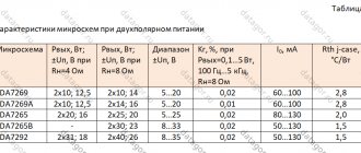
Single-board class AB audio power amplifiers (selection from Aliexpress): classics of the genre
The first single-chip audio power amplifier microcircuits were released several decades ago (you can describe this milestone with the words “in time immemorial” or “even the old-timers don’t remember,” although they never remember anything).
These chips gradually developed, expanded the bandwidth, increased the power, acquired a bridge output, and, finally, the most powerful and progressive of them had MOSFET (MOS) transistors at the output.
The last event turned out to be the last stage in their development: they had nowhere to develop further, and class D amplifiers entered the arena with their incredible efficiency, and at the same time with their not always positive features.
This selection of amplifiers of the classic genre will feature single-board amplifiers based on single-chip power amplifier chips, i.e. without discrete elements in the output stage (transistors or lamps).
Such amplifiers are small in size and weight, and, as a rule, (almost) do not require configuration: connect and use!
The selection shows approximate prices as of the date of review; in the future they can change in any direction. But during the 11.11 sale they will most likely decrease by several percent.
Prices are shown in dollars, as prices in rubles quickly become invalid (these are times like these!).
Single-board stereo power amplifier based on TDA7377 with tone control
Check current price or buy
The TDA7377 chip is built on conventional bipolar transistors and is a popular and time-tested amplifier with single-polar power supply.
The outputs of the single-board amplifier are bridged, thanks to which it can develop significant power even with a low supply voltage (8-18 V).
The TDA7377 chip itself can operate as a 4-channel chip with independent single channels, but this makes little sense (bridge outputs are better in all respects).
In reviews of this single-board amplifier, it is criticized for the small range of low-end tone control; but the board is assembled on the basis of ordinary elements (not SMD!), so everything is in the hands of the user.
Chinese sellers claim the amplifier's output power as 2*40 W, but the TDA7377's rated power is only 2*30 W; so, as always, information from Chinese sellers must be taken very critically.
Price - about $7.9.
Single-board stereo power amplifier based on TDA2030 with tone control
Check current price or buy
The TDA2030 (TDA2030A) chip is historically the first successful chip for amplifiers with bipolar power supply. The microcircuit is single-channel with a power of up to 15 W; There are two microcircuits on the board.
Amplifiers with bipolar power supply are among the most revered among Hi-Fi lovers. And this is largely justified: due to their symmetry with respect to the supply voltages, the influence of the quality of the power source on the sound quality is significantly reduced.
In fact, such amplifiers can be powered directly from a mains transformer with a rectifier.
This is exactly what is done in this single-board amplifier: a rectifier bridge and smoothing capacitors are located directly on the board. Although, if it is possible to place the rectifier and capacitors outside the board, it would be even better.
There is also a purely passive tone control on the board.
Price - about $8.4.
Single board mono power amplifier based on TDA2050
Check current price or buy
The TDA2050 chip is a further modification of its predecessor, TDA2030; Fully pin compatible.
It differs from its predecessor only in higher output power (35 W instead of 15 W for the TDA2030). The permissible supply voltage has also been slightly increased (up to 50 V instead of 44 V).
This board is single-channel, it implements a unipolar connection of the TDA2050 (which is allowed by the documentation for the TDA2050).
Although this is not the best use of the TDA2050, the user does not always have the opportunity to implement dual-polar power.
The board has an obvious drawback: the heat sink area clearly does not correspond to the power dissipation of the chip.
In this regard, if you plan to use the amplifier at high power, then you need to think about forced ventilation or installing a more serious radiator.
If you have the desire and the right hands, the board can be converted for bipolar power supply.
Price is about $4 including delivery.
Single-board 4-channel power amplifiers based on TDA7850
Simple board - check price or buy Complex board - check price or buy
The TDA7850 chip has MOSFETs in the output stages, 4 channels with bridge outputs, load resistance up to 2 Ohms, power 4*50 W. Fire!!!
If there is a gentleman driving a “car” under your windows at night and delighting the entire neighborhood with his favorite music; then know that most likely this particular microcircuit is installed in his radio!
The board in the first link is not immediately ready for use: it does not have a heat sink, and the user needs to solve this problem on his own.
In addition, it has a special feature: the BA3121 noise suppression chip. For its operation, the signal ground and power ground are separated on the board. If they are not combined anywhere outside the board, they must be connected on the board.
Price - approx. $7.7.
The payment in the second link is “sophisticated”. It contains a heat sink with forced ventilation, a Bluetooth channel and two volume controls.
Price - approx. $17.6.
Single board bridged mono power amplifier based on LM3886
Check current price or buy
The LM3886 (LM3886TF) chip is a single-channel power amplifier (68 W) with bipolar power supply.
The microcircuit has an insulated housing, which simplifies the choice of heat sink design (there will be no electrical potential on the heat sink).
In addition, like many other single-channel ULFs, it allows for easy construction of an amplifier with a bridge output from two microcircuits connected in antiphase.
This allows you to further increase the power and combine the advantages of bipolar power supply and bridge output.
True, with this connection method the load resistance should be doubled (from 4 to 8 Ohms); otherwise the current limit will be exceeded.
The presented board is built exactly according to this design and can deliver power up to 130 W.
To build a stereo amplifier you will need two such boards.
The board does not include a heatsink (which is required), so the consumer will have to take care of this.
Price: $25.
Single board bridged stereo power amplifier based on TDA7293/TDA7294
Check current price or buy
There are also a couple of related very powerful microcircuits for ULF with bipolar power supply: TDA7293 and TDA7294.
Both microcircuits are designed for an output power of 100 W and are built with DMOS transistors in the output stages, but are designed for different supply voltages: from ±12 V to ±50 V for the TDA7293 and from ±10 V to ±40 V for the TDA7294. Help: DMOS is a technology close to MOSFET.
This board has 4 microcircuits installed, operating in pairs in bridge mode.
The seller claims a power of 2*150 W for this configuration.
As always, we must remember that the load resistance for such a circuit must be double (8 ohms or more).
Also, the user will have to take care of the heatsink himself (attention: the heat sink of the microcircuit is under the potential of a negative power supply!).
Price is about $50 including delivery.
Example of a 60*150*25 radiator for amplifiers
Check current price or buy
Class AB amplifiers dissipate quite significant power and require heat dissipation.
Aluminum radiators are relatively expensive, and therefore, if possible, it is better to find them somewhere in unused equipment. For example, coolers with massive aluminum radiators were used to cool some older processors. Now these radiators can find a “second life”!
If you can’t find a suitable radiator, you can look for it on Aliexpress.
As an example, a link is given to a 60*150*25 radiator containing 24 fins. The total radiator area is about 800 square meters. cm.
Price - $4.2 including delivery.
Audio power amplifier chips in bulk
Check current price or buy
Most class AB ULF microcircuits have a design that is convenient for installation in amateur radio designs, even with wired installation.
In this regard, when no ready-made board is suitable for the intended design, you can develop your own board; and buy microcircuits for it separately, since bulk microcircuits are so cheap that they are most often sold not individually, but in sets of 2 - 10 pieces.
Using the link provided, you can purchase UMZCH microcircuits in sets of 5 pieces of the same name.
These are TDA7385 (4 bridge channels of 30 W each), TDA7388 (4 bridge channels of 41 W each), TDA7850 (4 bridge channels of 50 W each, MOSFET), TDA7851 (4 bridge channels of 48 W each, MOSFET).
Price - from $6.3 to $11.5 for 5 pieces. depending on the name.
Class AB amplifiers based on single-chip microcircuits have proven to be a solid and time-tested solution with high sound quality.
The output power of such microcircuits can be very significant.
In fact, if the consumer does not need to design equipment for sound recording of stadiums and concert halls, then for all other household needs designs based on such microcircuits will be quite sufficient.
In addition, it should be noted that they contain various types of protection (from overheating, from overcurrent, etc.), and also have high-quality thermal stabilization of modes due to the fact that the temperature sensor and the heat source are located in close proximity (on the same substrate ).
That is, with a power of up to 100 - 150 W, there is no need to assemble an amplifier from discrete elements.
The single-board amplifiers described in the selection can be used both for repairing radio equipment and for creating independent structures; including, for example, to revive “old Soviet” speakers (many of which are still alive and well among the population); or to return into operation “orphaned” speakers from radios and music centers after irreparable failure of the main device.
If the goods indicated in the descriptions are found cheaper from other sellers on Aliexpress, then you can also take them - the goods are the same (but you need to keep an eye on the shipping costs).
ULF testing on the TDA7850 chip
To conduct technical tests, a massive heat sink was attached to the chip using thermal paste (a heatsink from a cooler for the Intel Pentium IV S478 processor):
The measurements used a laboratory power supply LW-K3010D (review), a FY6800 generator (review), and a Hantek DSO5102P digital oscilloscope (review).
The tests were carried out at two supply voltages: 12 V (the most common option in cars and for battery power) and 18 V (the maximum permissible).
First, the consumption of the amplifier board was measured without supplying a signal. The idle current consumption varied depending on the supply voltage and amounted to the following values (rounded): 8 V - 210 mA 12 V - 220 mA 18 V - 220 mA. Such values of the quiescent current are moderate, but they cannot be called negligible.
When the supply voltage was below 7.8 V, the functionality of the amplifier was lost: the signal shape was distorted, and the amplitude dropped even for small signals.
The noise from the amplifier turned out to be very small and practically unnoticeable (can only be heard by bringing your ear close to the speaker).
Tests at 12 V supply voltage, 4 ohm load
Sine 1 kHz, amplitude on the verge of limitation (clipping):
The power delivered to the load in this mode is almost exactly 16 W.
The power consumption in this case is 22.1 W, efficiency = 72% (an error of several percent is possible due to the inaccuracy of measurements using an oscilloscope).
Next is a triangular signal, frequency 5 kHz, amplitude ~0.5 from the maximum:
The linearity of the triangle is very good, the vertices are sharp.
The next signal is a rectangle, frequency 5 kHz, amplitude ~0.5 from maximum:
Now the fronts of the rectangular signal are enlarged.
Leading Front:
Back Front:
On the fronts, short single “notches” are noticeable, extending beyond the audible range.
Signal - sine 100 kHz:
The same “notches” are noticeable on the slopes of the signal as on the fronts of the rectangular signal. But it is very pleasing that, in general, a signal of such a high frequency is not only reproduced, but also reproduced with low distortion.
Tests at supply voltage 18 V, load 2 Ohms (limit mode)
Now we move on to testing in the maximum permissible mode: with a power supply of 18 Volts (measured on a capacitor of 10,000 μF) and with a load of 2 Ohms (load - only in the channel under test, other channels - without load).
We start, as usual, with the sine. The frequency in all measurements was chosen to be 5 kHz in order to reduce the influence of the charging and discharging processes of the 10,000 μF capacitor on the results due to the higher frequency.
The oscillogram shows the maximum signal level when sine distortion is small and on the verge of detection. The load power in this mode was 54 W.
Power consumption from the power supply is 79.4 W, efficiency = 68%.
We add a little more signal level. Distortions are already becoming noticeable to the naked eye:
When running this test for a long time, the amplifier’s heatsink became very hot, in the area where the microcircuit was mounted, “the hand could not stand it” (i.e., the temperature was above 60 degrees).
And we add a little more signal level. Now the distortion is multiplied many times over as the overcurrent protection starts to kick in:
We assess the fact that the protection is triggered exclusively positively: what is more important to the consumer is not the extra milliwatts of power, but that the amplifier remains alive and well.
Now - a triangular signal for assessing linearity in the limiting mode:
Linearity is good, but not ideal: slight distortion is noticeable in the immediate vicinity of the vertices. But the regime is the limit!
And finally, we run the rectangle at the maximum amplitude that does not trigger the current protection:
The load power in this mode was 60 W.
Frequency response (supply voltage 12 V, load 4 ohms)
The frequency response was measured by applying a signal with a linearly increasing frequency to the input of the amplifier; and then an oscillogram was recorded, taken from the signal maxima. It represents the frequency response of the amplifier.
First pass, range 10 Hz - 40 kHz:
One repetition period of a signal with a linearly increasing frequency is marked with a red frame; it represents the frequency response in the range of 10 Hz - 40 kHz.
The horizontal scale of the graph is 3.6 kHz/division.
The drop in frequency response towards the end of the measured range is very small and can be neglected.
Second pass, range 10 Hz - 400 Hz (for more detailed viewing of the lower frequencies):
The horizontal scale of the graph is 36 Hz/division.
At the beginning of the frequency band (close to 10 Hz), a significant decline is noticeable; but, already starting from a frequency of 20 Hz, the level of frequency response can be considered quite satisfactory.
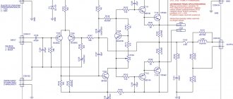
TPA3116 Class D amplifier circuit
It’s especially pleasing that there are all sorts of built-in protections (short circuit, overheating, excess supply voltage). Indeed, during the process of setup and operation, all sorts of accidents inevitably arise, from which the ULF parts may suffer. See the datasheet for more details.
Electrical circuit of the TPA3116 amplifier
With a unipolar power supply of 12 V, the output power is about 10 W, at 24 V - about 30 W (at 8 Ohm AC).
Power - ULF distortion, graph
Judging by the distortion graphs, there’s no need to pump it up too much, up to 20 W and that’s it. Then Kni climbs sharply upward.
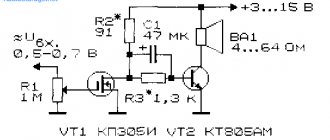
Useful: T-class amplifier on TK2050 chip
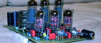
Block board TPA3116, TPA3118, TPA3130
Despite the modest size of the board and the unusual absence of radiators for an audio assembler, this little guy plays very loudly. The assembly itself took a couple of hours - you don’t need to do anything special, just solder the wires from the connectors and the power supply. But try to do everything as efficiently as possible so that you don’t have to disassemble and redo it later. These UMZCH modules are most often powered by switching power supplies, which whistle and make noise along the circuit. Therefore, install additional capacity filters that will eliminate these effects.
Please note the additional TIP-142 power filter transistor. It was assumed that it would heat up a little, so the transistor was screwed to the body. In reality he is cold. An additional advantage is that the voltage increases gradually through this filter, after switching on for a short time.
In general, for power supply, one more 50V/6800uF capacitor per channel was installed in front of the modules. TPA3116 boards are installed vertically using bushings. If you want the end result to leave a good impression, find a good volume control knob and good audio connections. External power also comes through the socket.