The audio range covers frequencies from 20 Hz to 20 kHz. A person with normal hearing can perceive these vibrations. In hi-and systems, the reproduced frequency band can be expanded from 15 Hz to 40 kHz. These systems have complex design solutions. Simple circuits that provide satisfactory sound quality can be assembled on your own. The audio amplifier circuit, which is not difficult to make with your own hands, does not contain scarce parts and is available for repetition. Such a circuit can provide a frequency band within the range of 50 Hz-15 kHz with a nonlinear distortion coefficient of no more than 0.1% and provide an output power of 10-15 watts to a low-impedance load. You can assemble a sound amplifier circuit using both transistors and integrated circuits.
Simple audio amplifier circuit
Any low-frequency stage intended for music reproduction consists of a preliminary block, tone controls or equalizer, and a final stage. If the device is intended to work with multiple audio sources, an input selector should be provided. Since the signal level from different devices differs from each other, the selector takes into account the possibility of equalizing the input voltages through amplification or limitation. The most sensitive is the microphone input, and the “roughest” is the input intended for connecting the linear output of a radio or tuner. The circuit diagram of the preliminary stage can be assembled using transistors or operational amplifiers.
A simple audio amplifier circuit with sound controls and tone controls is implemented on a single reverse conduction transistor. In the circuit it is recommended to use KT315 or KT3102 with any letter index. Resistor R8, on the collector of the transistor, sets the voltage to 6 volts, and resistor R1 can be replaced with a constant one. Its value is selected depending on the input signal level.
It is easy to assemble an audio amplifier circuit with your own hands using an operational amplifier, which has a high input impedance, a wide processing bandwidth and a low level of intrinsic noise.
This circuit uses the K1401UD2 microcircuit, which contains 4 separate nodes with a common power supply. This chip assembles the preliminary channel for the stereophonic path. 2 op-amps operate in the right channel and 2 in the left. In the monophonic version, only two elements can be used. The device consists of a pre-level increase channel with input voltage correction and an active three-band tone control that operates at low, mid and high frequencies. A significant disadvantage of preliminary stages on operational circuits is that they require a bipolar power supply, which significantly complicates the design.
The sound power amplifier can also be made on a different element base. Most often, complementary pairs of transistors of different conductivities or specialized integrated circuits are used for this purpose. A simple cascade is assembled using low-power silicon transistors. Instead of the KT315-KT361 pair, you can use the KT3102-KT3107 pair.
Before applying power, the speaker should be turned off, and instead of resistor R1, install a chain of a 33 kOhm constant resistor and a 270 kOhm potentiometer connected in series. Turn on the power and rotate the potentiometer to set the specified collector current at the control point. Then measure the resulting resistance of the chain and replace it with the closest nominal constant resistor. Next, by selecting resistor R3, you need to set half the supply voltage at the same point. Next, a speaker is connected and a low-frequency signal from the sound source is supplied to the input. The circuit does not have a volume or tone control, so any pre-stage that has these functions can be connected to it.
↑ Let's move on to solving technological issues
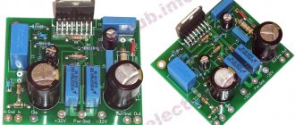
Many people are confused by the power supply and reliability of the mute and stby circuits. Agree, keeping two power poles on one toggle switch is simply dangerous, especially if the toggle switch is more than budget. More than one microcircuit has failed due to such tricks. I also took care of ensuring the reliability of this unit by placing a 12V parametric stabilizer, shown in the figure, directly on the printed circuit board.
↑ Stabilizer
The service circuits of the microcircuit are powered from it. A three-pin jumper is installed as outputs. This allowed us to solve several problems at once:
— If control of the microcircuit is not needed, it is simply fixed in the Play! position, the amplifier is constantly in an unlocked state and is ready for use every second.
— If, say, the rear channels are not used in a multi-channel amplifier for a long time, you can move the jumper to the Mute position, this will block the input and output stages of the microcircuit and its consumption will be reduced to microscopic standby currents.
— You can connect an external ON-ON toggle switch to the jumper, such as the available MTS102.
The diagram also shows an example of a microcircuit power indicator, assembled using R14 LED1 elements. R14 acts as a current source of approximately 5mA for LED1, which lights up in the Play position! and goes out in Mute mode. In addition, even if the toggle switch malfunctions and its +Up-Ground contacts are closed, nothing bad will happen, since the current is limited by resistor R11 at a safe level. The C11 C12 capacitances are doubled compared to standard ones to provide greater turn-on delay and prevent clicking in the speakers even during long-term charging of the power supply.
Homemade sound amplifier
Before you start choosing a low-frequency block circuit, you need to find out for what purpose it will be used. One of the popular models is the headphone circuit, since many household systems do not provide good volume along with high sound quality. The two-channel audio amplifier circuit can be used for a personal computer or car radio. This makes it possible to listen to music in the cabin without disturbing others.
The basis of the device is a low-voltage opamp. The power supplied to pin 2 of the microcircuit ranges from 3 to 12 volts. There are similar circuits made on discrete elements, but the microcircuit does not require adjustment and configuration, which is important in transistor circuits. A correctly assembled amplifier starts working immediately. The speaker amplifier demonstrates a more complex design, where characteristic attention is paid to sound quality.
↑ Sound of amplifier MF1
The sound was discussed separately in the introductory note of the article, but more specific listening sensations should also be shared. The first word that comes to mind when listening is hurricane sound. This is perhaps the most accurate word. The amplifier easily digests the most complex material in terms of dynamics. He plays quickly and uncontrollably, but at the same time quite delicately.
The question immediately arises - where did the washed-out electronic sound of the TDA7294 go? The bass response is simply amazing. True, it is not as deep and booming as, say, the Quad 405 or tubes, but the development and attack are simply amazing - like a shot, not the slightest delay, not the slightest hint of the front being delayed.
Vocals are finally heard openly and pleasantly, filling the entire space with sound. In general, vocals and high frequencies are the strong point of current control. All nuances and halftones are conveyed, not a single detail is missed, the response of the speakers is compensated, so all the accompanying noise and dirt also disappears, and the music is transmitted in a crystalline, pristine form.
↑ Let's go through my favorite test compositions:
Alegria (Toyota business car) - lush metal electronics, energetic vocals, no characteristic hoarseness, which, as a rule, is conveyed by low-quality UMZCH. The vocals sound mesmerizing, causing characteristic goosebumps.
Away From Me (Evanescence) - already the first notes speak about the quality of the development of ultra-low frequencies, the introduction covers with a wave, from which piercingly filled vocals suddenly materialize, as they should be.
Yeah! (Usher) - the subwoofer on the 75GDN, which is loaded with the amplifier for this track, suddenly explodes with juicy rapper beats. For some reason, the glass in the bookshelf and something covered in a thick layer of dust on the cabinet begin to clink.
Eternal (Evanescence) is a characteristic test for transmitting the nuances of the mid-high frequency spectrum. The sound of each individual drop of rain is clearly audible, and drops falling on the ground are easily distinguishable from those falling on a metal roof. Just now the color of the roof is unclear.
Procession of the Dwarves (Grieg) - perfectly reveals the dynamic range. There are at least 3 main volume levels in a track. The amplifier jumps from one to another with such speed that you can’t believe that you’re listening to the same composition. So insinuating, at the limit of audibility, the introduction is far from the juicy noise attack that follows it.
A simple DIY audio amplifier circuit
When creating a homemade device, a radio amateur has to solve many different problems. One of them is related to the output power, which is limited by the supply voltage. First of all, this applies to car systems, since they receive power from the on-board network. An exemplary option would be to use individual microcircuits. The circuit of a complete audio amplifier is a pre-stage with effective tone controls and a final block. The proposed design contains the following characteristics:
- Output power – 20 WX 2
- Frequency band – 40 – 18,000 Hz
- Distortion factor – 1.0%
- Supply voltage – 8-18 V
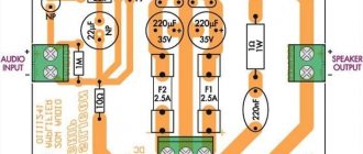
Sound amplifier for speakers printed circuit board diagram A powerful amplifier on a microcircuit assembled with your own hands can be used at home or installed in a car.
Audio amplifier for speakers circuit board circuit
The printed circuit board for this circuit is made of foil-coated PCB by etching. The pattern of printed tracks can be applied with asphalt-bitumen varnish or other composition. The easiest way to etch a board is in a ferric chloride solution. In order for the audio amplifier on a microcircuit, made by yourself, to work stably, we install the TDA1552Q element on the radiator. To obtain good sound and minimal distortion, capacitors C11, 12, 13 and 14 must be film. Resistors R7 and R8 set the maximum undistorted signal on the speaker systems.
Audio amplifier circuit
Integrated circuits are gradually replacing transistors from low-frequency amplifier circuits. TDA2005-2052 devices have become widespread. They provide sufficient output power to provide sound for a car interior or living room. A simple DIY stereo audio amplifier can be assembled on a single TDA2005 chip.
It is better to use film capacitors C8 and C12. If the supply voltage does not exceed 12 V, then all electrolytic capacitors must be 16 V. With a higher supply voltage, the operating voltage of the capacitors must be increased. A self-assembled amplifier is used for speakers with a resistance of 2 to 4 ohms.
Contents
- 1. Introduction
- 2 Idea? A whole ideology! 2.1 So, let’s consider the postulates of the modern vision of circuit design for budget simple UMZCHs.
- 5.1 Stabilizer
- 6.1 Resistors
- 10.1 1. Inverting with T-feedback
- 11.1 Let's go through my favorite test compositions:
Audio amplifier circuit
They include such solutions when the integrated circuit is made in the final stage, and the preliminary path is assembled using transistors. To assemble the final audio amplifier with your own hands on a microcircuit, you will need a small number of parts. The microcircuit body has built-in protection circuits against short circuits, overloads and over-temperatures, so the system uses only transition capacitors and a power filter. It’s not difficult to make a sound amplifier with your own hands using a 174 series microcircuit.
The device includes an integrated circuit and 8 capacitors, so the circuit board is easy to draw yourself.
↑ Introduction
The MF1 amplifier is the long-promised result of my development in the field of current control - an inverting semi-ITUN with an F-shaped hybrid feedback loop. Includes both voltage and current feedback. Hurricane, clear and dynamic sound. The basis is the popular TDA7294 or any of the family, but the circuitry can be used with any other.
— Hurricane, dynamic and collected sound — Full control of the speaker operation — Unique circuit design that combines the best trends in achieving live sound — Circuit reliability even in the most extreme modes — Availability of repetition. The basis is the popular TDA729x - a unique printed circuit board topology that allows you to assemble at least 4 different amplifier options without changing the wiring. — All the requirements of even the most picky audiophile critics are taken into account.
The simplest audio amplifier circuit
The simplest device consists of an integrated circuit and two capacitors. One of them is separating, and the second works as a power filter. The device does not require adjustment and, if assembled correctly, starts working immediately after switching on. The audio amplifier connection circuit allows power from a car battery.
The terminal circuit is made on a TDA7294 chip. The rated power delivered to a 4 ohm load is 70 watts, and the maximum is 100 watts. The chip is used for wideband speaker systems or a subwoofer. To obtain such power, you will need a bipolar power supply with a voltage of 35 volts.
Simple DIY sound amplifier
You can assemble an audio amplifier with your own hands without microcircuits using any transistors, including both bipolar and field-effect ones. The use of field-effect transistors in the output stage made it possible to create a device whose characteristics are close to those of tube designs.
The scheme has the following characteristics:
- The frequency response is linear in the range 20 Hz-100 kHz
- Distortion rate at 1 kHz does not exceed 0.003%
- Output power 10 watts into 8 ohm load
To drive the output stage, a voltage of 0.7 volts is required, which must be provided by the preliminary stage. The NE5534 operational amplifier can be replaced with the domestic op-amp KR140UD608. Zener diodes must be designed for a stabilization voltage of 18 volts. The 1N4705 can be replaced by two semiconductors in series, 9 volts each.