Low frequency amplifiers (LF) are used to convert weak signals, predominantly in the audio range, into more powerful signals acceptable for direct perception through electrodynamic or other sound emitters.
Note that high-frequency amplifiers up to frequencies of 10 ... 100 MHz are built according to similar circuits; the difference most often comes down to the fact that the capacitance values of the capacitors of such amplifiers decrease as many times as the frequency of the high-frequency signal exceeds the frequency of the low-frequency one.
A simple amplifier with one transistor
The simplest ULF, made according to a circuit with a common emitter, is shown in Fig. 1. A telephone capsule is used as a load. The permissible supply voltage for this amplifier is 3…12 V.
It is advisable to determine the value of the bias resistor R1 (tens of kOhms) experimentally, since its optimal value depends on the supply voltage of the amplifier, the resistance of the telephone capsule, and the transmission coefficient of a particular transistor.
Rice. 1. Circuit of a simple ULF on one transistor + capacitor and resistor.
To select the initial value of resistor R1, it should be taken into account that its value should be approximately one hundred or more times greater than the resistance included in the load circuit. To select a bias resistor, it is recommended to connect a constant resistor with a resistance of 20...30 kOhm and a variable resistor with a resistance of 100...1000 kOhm in series, after which, by applying a small amplitude audio signal to the input of the amplifier, for example, from a tape recorder or player, by rotating the variable resistor knob to achieve the best signal quality at its highest volume.
The capacitance value of the transition capacitor C1 (Fig. 1) can range from 1 to 100 μF: the larger the value of this capacitance, the lower frequencies the ULF can amplify. To master the technique of amplifying low frequencies, it is recommended to experiment with the selection of element values and operating modes of amplifiers (Fig. 1 - 4).
Part 5
In terms of sound, the circuit turned out to be very sensitive to the quality of installation and the amount of soldering, so much so that the cathode circuit had to be radically minimized: the cathode resistor was soldered with one terminal directly to the lamp leg, and the other to the common point of the circuit. The installation of the input stage and volume control circuits is made with Jensen silver monocore with a diameter of 0.8 mm. All other circuits are made of copper wire.
Also, this circuit is very sensitive to the type of cathode resistor. Carbon ones, including BLP, turned out to be simply disgusting, wire ones were satisfactory, but nothing more. I didn’t really like the PTMN at all, although I collected a monstrous number of them for experiments. As a tuning element for obtaining the desired color of the sound of the amplifier as a whole, the cathode resistor is unsuitable.
The anode resistor of the first stage is the ideal element for the necessary touch-up of the amplifier's sound! The choice of the type of this resistor has a direct impact on the sound.
Currently I have this tantalum foil resistor, but I still haven’t been able to make a final choice between it and the Riken Ohm. Their sound is different: Riken Ohm gives a very beautiful color to the mids, some special dynamics, softening the top and slightly blurring the detail, while tantalum is sterile and very detailed.
It was with tantalum resistors that I was ambushed. About a year ago, having poured out my thoughts on the Internet (www.dvdworld.ru/cgi-bin/audiobbs.pl) about the sound qualities of various resistors, I rejected tantalum. But my later research showed that this was a trap, which I myself warned against falling into. The fact is that a good component may seem “bad” if, as a result of its installation in the circuit, the shortcomings of other path components appear. And the sharpness of the sound, which then seemed to me to be a property of tantalum, actually turned out to be a drawback of my then DAC. Now justice has prevailed, but I still like the sound of Riken Ohm.
In the leakage of the first stage, it is better to use something film - good and precise. It’s not by chance that I’m talking about precision resistors. Usually this means increased quality of the resistor in general. (In the second stage it is not so critical - you can use both film and carbon.) I suspect that tantalum or copper foil will be even better, but so far I have not been able to find them for such low denominations. The best here so far have been domestic C2-10. [12]
[12] C2-10 are high-frequency accurate, which is clearly visible upon external inspection. Main features:
- Shiny, unpainted caps.
- There are no spiral grooves on the conductive layer—non-inductive.
- There are traces of fitting - longitudinal cuts made with a diamond blade.
- Some resistors have a dark bluish metallic tint to the conductive layer coating.
As for the choice of capacitor C4, my choice of FT is simply determined - this is the best of what I have tried. I can say the same for FT as for tantalum resistors: neutrality and detail without poison or harshness. I won't say that they are the best at all. For example, I really want to try the famous Jensen copper capacitors (paper-oil), which S. Rubtsov and O. Khavin spoke very positively about. As we say: “If there is money, there will be copper and oil!”
The following capacitors were tapped: MBM, K40-U9, K73, K71 - everything is very bad! MultiCap RTX and PPFX, aluminum Jensen (paper - oil) 1973 [13], SSG, K31 - passable, but no more.
[13] The failure with the Jensen was probably due to the fact that they were old and purely electrical, despite the fact that they were ripped out of some Audio Note.
If you are planning to build an amplifier, then I strongly recommend planning the costs of output transformers as follows:
- Having a certain amount of money to build an amplifier and intending to spend it more or less immediately, set aside half and no less for transformers.
- If you plan to spend a certain amount over a long period of time (gradual development), then increase the cost of trannys to two-thirds of this amount. Spending becomes easier over time.
Output transformers (or any transformers in general!) are never too good, there is simply not enough money. Even if you install cheap hardware in a good and “correct” circuit, a miracle will not happen, it will not play as well as it could. The transformer is the heart of the amplifier.
Unfortunately, serious technology for manufacturing high-quality transformers, especially for single-ended amplifiers, has not come up with cheap solutions over the last 80 years. So I don’t advise you to flatter yourself with the hope of winding a high-quality output transformer yourself in the kitchen. By the time you become more or less bearable with them, age-related diseases will have already set in, including hearing loss.
The production of truly good transformers is within the power of well-coordinated teams, for example, our native ERAudio from Novosibirsk or foreign guys from Tamura-Magnequest-Sowter and others. At the same time, I would like to remind you once again the story that Tango transformers [14] ceased production due to the advanced age of the Japanese grandfathers who made them, who were never able to pass on their accumulated experience to the younger generation.
[14] Currently, Tango transformers continue to be produced in Japan, but by a different “team of authors.” Their range has thinned out by more than two-thirds, and expensive and high-quality single-cycle models have completely disappeared from it. Tango transformers of previous years are now gradually becoming antiques, including in terms of price. — Approx. ed.
Improved single-transistor amplifier options
More complicated and improved compared to the diagram in Fig. 1 amplifier circuits are shown in Fig. 2 and 3. In the diagram in Fig. 2, the amplification stage additionally contains a chain of frequency-dependent negative feedback (resistor R2 and capacitor C2), which improves the quality of the signal.
Rice. 2. Diagram of a single-transistor ULF with a chain of frequency-dependent negative feedback.
Rice. 3. Single-transistor amplifier with a divider to supply bias voltage to the base of the transistor.
Rice. 4. Single-transistor amplifier with automatic bias setting for the transistor base.
In the diagram in Fig. 3, the bias to the base of the transistor is set more “rigidly” using a divider, which improves the quality of operation of the amplifier when its operating conditions change. “Automatic” bias setting based on an amplifying transistor is used in the circuit in Fig. 4.
Story
- 1904 - Lee de Forest, based on the electron tube he created - a triode - developed a device for amplifying electrical signals (amplifier), consisting of a nonlinear element (lamp) and a static resistance Ra connected to the anode circuit.
- 1932 - Harry Nyquist determined the conditions for stability (the ability to operate without self-excitation) of amplifiers covered by negative feedback.
- 1942 - the first operational amplifier was built in the USA - a direct current amplifier with a symmetrical (differential) input and a significant intrinsic gain (more than 1000) as an independent product. The main purpose of this class of amplifiers was its use in analog computing devices to perform mathematical operations on electrical signals. Hence its original name - decisive.
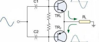
Two-stage transistor amplifier
By connecting two simple amplification stages in series (Fig. 1), you can obtain a two-stage ULF (Fig. 5). The gain of such an amplifier is equal to the product of the gain factors of individual stages. However, it is not easy to obtain a large stable gain with a subsequent increase in the number of stages: the amplifier will most likely self-excite.
Rice. 5. Circuit of a simple two-stage low-frequency amplifier.
New developments of low-frequency amplifiers, the circuit diagrams of which are often presented on the pages of magazines in recent years, are aimed at achieving a minimum coefficient of nonlinear distortion, increasing output power, expanding the bandwidth of amplified frequencies, etc.
At the same time, when setting up various devices and conducting experiments, a simple ULF is often needed, which can be assembled in a few minutes. Such an amplifier must contain a minimum number of scarce elements and operate over a wide range of changes in supply voltage and load resistance.
ULF circuit based on field-effect and silicon transistors
The circuit of a simple low-frequency power amplifier with direct coupling between stages is shown in Fig. 6 [Rl 3/00-14]. The input impedance of the amplifier is determined by the rating of potentiometer R1 and can vary from hundreds of ohms to tens of megohms. You can connect a load with a resistance from 2...4 to 64 Ohms and higher to the amplifier output.
For high-resistance loads, the KT315 transistor can be used as VT2. The amplifier is operational in the range of supply voltages from 3 to 15 V, although its acceptable performance is maintained even when the supply voltage is reduced to 0.6 V.
The capacitance of capacitor C1 can be selected in the range from 1 to 100 μF. In the latter case (C1 = 100 μF), the ULF can operate in the frequency band from 50 Hz to 200 kHz and higher.
Rice. 6. Circuit of a simple low-frequency amplifier using two transistors.
The amplitude of the ULF input signal should not exceed 0.5...0.7 V. The output power of the amplifier can vary from tens of mW to units of W depending on the load resistance and the magnitude of the supply voltage.
Setting up the amplifier consists of selecting resistors R2 and R3. With their help, the voltage at the drain of transistor VT1 is set equal to 50...60% of the power source voltage. Transistor VT2 must be installed on a heat sink plate (radiator).
Intro
Actually, sound is a matter of taste. From the circuit I tried to achieve neutrality, detail [1] and audibly even timbre and frequency balance, as a starting point for further procedures. Sort of like a blank canvas.
[1] By detail, I mean the transfer of subtle shades of timbre, reverberation, the naturalness of the attenuation of sounds, aftersound... It, detail, is manifested in the naturalness of the transfer and the natural dynamics of sounds that are well known to us, absorbed by us since childhood.
As for music, here, especially on poorly made recordings, sometimes you want to touch up something or, conversely, cover it up. Up to setting the switch “soft - neutral - dynamic”.
As a result, all solutions were finally selected (or rejected) by listening. This is my amp and it sounds the way I think it should. Without claims to Absoluteness...
At the same time, I didn’t really focus on the fact that the scheme would not tolerate free intervention and would not be suitable for dummies with modest incomes. But, despite its apparent simplicity, the amplifier circuit took a long time to polish—several years. Its capabilities will be revealed only with a good source and acoustics.
To my ears, the amplifier came out of the soldering iron transparent enough to get any desired type of sound by selecting the appropriate parts [2]. If one of you or your friends at least tries the first cascade (in fact, the whole highlight is in it!) in the most strict environment, it would be absolutely great! Otherwise, references to rave reviews from only one person, moreover, the author of the scheme, are not entirely convincing.
[2] First of all, this is the anode resistor of the first stage and the interstage capacitor. Well, the other components also mean something...
Track-cascade ULF with direct coupling
In Fig. Figure 7 shows a diagram of another seemingly simple ULF with direct connections between cascades. This kind of connection improves the frequency characteristics of the amplifier in the low-frequency region, and the circuit as a whole is simplified.
Rice. 7. Schematic diagram of a three-stage ULF with direct connection between stages.
At the same time, tuning the amplifier is complicated by the fact that each amplifier resistance has to be selected individually. Approximately the ratio of resistors R2 and R3, R3 and R4, R4 and R BF should be in the range (30...50) to 1. Resistor R1 should be 0.1...2 kOhm. Calculation of the amplifier shown in Fig. 7 can be found in the literature, for example, [R 9/70-60].
Cascade ULF circuits using bipolar transistors
In Fig. 8 and 9 show circuits of cascode ULFs using bipolar transistors. Such amplifiers have a fairly high gain Ku. Amplifier in Fig. 8 has Ku=5 in the frequency band from 30 Hz to 120 kHz [MK 2/86-15]. ULF according to the diagram in Fig. 9 with a harmonic coefficient of less than 1% has a gain of 100 [RL 3/99-10].
Rice. 8. Cascade ULF on two transistors with gain = 5.
Rice. 9. Cascade ULF on two transistors with gain = 100.
Economical ULF with three transistors
For portable electronic equipment, an important parameter is the efficiency of ULF. The diagram of such a ULF is shown in Fig. 10 [RL 3/00-14]. Here, a cascade connection of field-effect transistor VT1 and bipolar transistor VT3 is used, and transistor VT2 is connected in such a way that it stabilizes the operating point of VT1 and VT3.
As the input voltage increases, this transistor shunts the emitter-base junction of VT3 and reduces the value of the current flowing through transistors VT1 and VT3.
Rice. 10. Circuit of a simple economical low-frequency amplifier with three transistors.
As in the above circuit (see Fig. 6), the input resistance of this ULF can be set in the range from tens of ohms to tens of megohms. A telephone capsule, for example, TK-67 or TM-2V, was used as a load. The telephone capsule, connected using a plug, can simultaneously serve as a power switch for the circuit.
The ULF supply voltage ranges from 1.5 to 15 V, although the functionality of the device is maintained even when the supply voltage is reduced to 0.6 V. In the supply voltage range of 2 ... 15 V, the current consumed by the amplifier is described by the expression:
1(μA) = 52 + 13*(Upit)*(Upit),
where Upit is the supply voltage in Volts (V).
If you turn off transistor VT2, the current consumed by the device increases by an order of magnitude.
Two-stage ULF with direct coupling between stages
Examples of ULFs with direct connections and minimal selection of operating modes are the circuits shown in Fig. 11 - 14. They have high gain and good stability.
Rice. 11. Simple two-stage ULF for a microphone (low noise level, high gain).
Rice. 12. Two-stage low-frequency amplifier using KT315 transistors.
Rice. 13. Two-stage low-frequency amplifier using KT315 transistors - option 2.
The microphone amplifier (Fig. 11) is characterized by a low level of self-noise and a high gain [MK 5/83-XIV]. An electrodynamic type microphone was used as the VM1 microphone.
A telephone capsule can also act as a microphone. Stabilization of the operating point (initial bias at the base of the input transistor) of the amplifiers in Fig. 11 - 13 is carried out due to the voltage drop across the emitter resistance of the second amplification stage.
Rice. 14. Two-stage ULF with field-effect transistor.
The amplifier (Fig. 14), which has a high input resistance (about 1 MOhm), is made on a field-effect transistor VT1 (source follower) and a bipolar transistor - VT2 (with a common one).
A cascade low-frequency amplifier using field-effect transistors, which also has a high input impedance, is shown in Fig. 15.
Rice. 15. circuit of a simple two-stage ULF using two field-effect transistors.
Literature
- Simonov Yu. L. Intermediate frequency amplifiers. - M.: Soviet radio, 1973
- Bukreev S. S. Transistor low-frequency amplifiers with feedback. - M.: Soviet radio, 1972
- Voishvillo G.V. Amplifier devices: Textbook for universities. 2nd ed. — M.: Radio and communications. 1983
- Handbook of radio-electronic devices: Vol. 1 / Ed. D. P. Linde - M.: Energy, 1978
- Ramm G. S. Electronic amplifiers.
- Shamshin V. G. History of technical means of communication, 2003.
- Kuleshov V.N., Udalov N.N., Bogachev V.M.
and others. Generation of oscillations and formation of radio signals. - M.: MPEI, 2008. - 416 p. — ISBN 978-5-383-00224-7.
Regulatory and technical documentation
- GOST 23849-87. Household radio-electronic equipment. Methods for measuring electrical parameters of audio frequency signal amplifiers.
- GOST 24388-88. Household audio signal amplifiers. General technical conditions.
- GOST 29180-91. Electromagnetic compatibility of technical equipment. Microwave devices. The amplifiers are low noise. Parameters and characteristics. Measurement methods.
- OST4-203.007-84. Equipment for sounding open and closed spaces. Audio amplifiers. General technical conditions.
- OST45-138-99. Audio frequency terminal amplifiers for wired broadcasting stations. Main parameters. Measurement methods.
- IEC 60527(1975). DC amplifiers. Characteristics and test methods.
- IEC 60581-6(1979). Acoustic equipment and high fidelity systems (Hi-Fi). Minimum requirements for parameters. Part 6. Amplifiers.
- IEC 61305-3(1995). Household audio equipment and high-fidelity audio systems. Methods for measuring and establishing performance characteristics. Part 3: Amplifiers.
- IEC 60268-3(2000). Sound system equipment. Part 3. Amplifiers.