So I decided to write an article myself, which is very important for acousticians. In this article I want to describe ways to measure the most important parameters of dynamic heads - the Thiel-Small parameters.
Remember! The following method for measuring Thiel-Small parameters at home is only effective for measuring Thiel-Small parameters of speakers with resonant frequencies below 100 Hz (i.e., woofers); at higher frequencies the error increases.
The most basic Thiel-Small parameters, which can be used to calculate and manufacture an acoustic design (in other words, a box) are:
- Speaker Resonance Frequency Fs (Hertz)
- Equivalent volume Vas (liters or cubic feet)
- Full quality Qts
- DC resistance Re (Ohm)
For a more serious approach, you will also need to know:
- Mechanical quality factor Qms
- Electrical quality factor Qes
- Diffuser area Sd (m2) or diameter Dia (cm)
- Sensitivity SPL (dB)
- Inductance Le (Henry)
- Impedance Z (Ohm)
- Peak power Pe (Watt)
- Mass of the moving system Mms (g)
- Relative stiffness (mechanical flexibility) Cms (meters/newton)
- Mechanical resistance Rms (kg/sec)
- Motor power (product of induction in the magnetic gap by the length of the voice coil wire) BL (Tesla*m)
Most Thiel-Small parameters can be measured or calculated at home using not particularly sophisticated measuring instruments and a computer or calculator that can extract roots and exponentiate. For an even more serious approach to designing acoustic design and taking into account the characteristics of speakers, I recommend reading more serious literature.
The author of this “work” does not claim any special knowledge in the field of theory, and everything presented here is a compilation from various sources - both foreign and Russian.
Measurement of Thiel-Small parameters Re, Fs, Fc, Qes, Qms, Qts, Qtc, Vas, Cms, Sd, Mms.
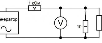
To carry out Thiel-Small measurements you will need the following equipment:
- Voltmeter.
- Audio frequency signal generator. Generator programs that generate the necessary frequencies are suitable. Like Marchand Function Generator or NCH tone generator. Since it is not always possible to find a frequency meter at home, you can completely trust these programs and your sound card installed on your computer.
- Powerful (at least 5 watts) resistor with a resistance of 1000 ohms.
- Accurate (+- 1%) 10 ohm resistor.
- Wires, clamps and other rubbish to connect it all into a single circuit.
Rice. 1. Scheme for measuring Thiel-Small parameters
Measuring TS parameters of a speaker using a computer.
Those who were involved in the calculation of acoustic design encountered the Thiel-Small parameters. To, for example, calculate the acoustic design for a speaker, you need to know at least 3 basic parameters:
Vas – equivalent volume;
Qts – total quality factor;
Fs – resonant frequency.
Most manufacturers do not indicate these parameters, but write on the boxes all sorts of beautiful numbers and other “nonsense” that has little to do with the speaker (for example, 1300 watts, etc.). There is a wonderful program called AudioTester, which can do a lot, including measuring the parameters of woofers. You can download the program for free at off. website, but it will constantly remind us to purchase the full version, and after several measurements it closes, but the functionality is complete. Download the file (about 30MB), click Download in the upper left corner of the site, install the program. We need to assemble such a simple circuit, buy a couple of plugs and a couple of 10-ohm resistors.
Scheme.
Tester, cord, 25GDN and 15ohm resistor.
We launch the program, click TSP on the left, do the settings as I did, remove equalizers and so on in the sound card settings, set the input-output level to 60-80%. First you need to calibrate the resistance, for this we find a 10-20 ohm resistor, measure its resistance with a tester, or look for a resistor with a small error.
The resistance measurement showed 15.9 ohms, but this is not entirely true.
I had this 15 ohm ceramic resistor lying around, and in order to measure its resistance as accurately as possible, you need to subtract the readings on the tester (device) with the resistor connected and the readings with short-circuited probes (15.9-0.9 = 15 ohms), it coincided with the nominal value, but This rarely happens.
When the probes are closed, the resistance is 0.9 ohms
The probes and internal circuitry of the tester also have resistance, and this should not be neglected.
We connect the cord to the input and output of the computer’s sound card (for me it’s line out and line in, for some reason it doesn’t work with the microphone input), connect a 15 ohm resistor to the cord, run the program, click Start and achieve (by changing the value of the reference resistance) that so that the line on the graph coincides with the 15th scale, at the same time we will check the suitability and linearity of the sound card (for me it turned out just perfect, see the blue line in the photo)
First launch and calibration.
So, we have calibrated our cord, now we can safely measure the parameters of the speakers. For example, I took the Soviet 25GDN 86g.v. We select the frequency range from 5Hz to 120Hz (Fs=78Hz), for subwoofers the upper frequency can be reduced to 100Hz, but it is better not to raise the lower measurement frequency, since the accuracy will suffer (Rdc will become higher). We place the speaker vertically, hang it, or hold it in our hands during the measurement, set the appropriate settings in the program, press start, wait for the program to build a graph. Now we drag the graph into the window (1. Measurement), and the program will instantly calculate the parameters.
Measurement of parameters of 25 GDN.
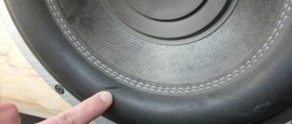
The most difficult thing is determining the equivalent volume. To do this, use a ruler to measure the diameter of the diffuser from the middle to the middle of the suspension, glue coins onto double-sided tape based on approximately the ratio: mass of coins = mass of the moving system (5 inches-10g, 6.5 - 20g, 8 - 40g, 10 - 90g, 12 - 120g , 15 – 180g), but depends on the design of the woofer. You can find out the weight of coins here; it is better to take those that are not magnetic. We switch to the second graph, in the settings we indicate the mass of coins and the diameter of the speaker, click Start and build a resistance dependence with an additional weight, drag it into the window (2. Measurement). That's it, the program gives us the remaining Vas and so on. You can save the data by clicking Print/List.
Additional load - 2 coins of 10 rubles.
Also, using this cord, you can find out the speaker resistance at a certain frequency (filter crossover frequency, for example), which will help when calculating passive filters. At high frequencies, the resistance will no longer be 4 ohms (this is due to the large inductance of the woofer speaker coil).
Dependence of resistance on frequency 25GDN
You can very accurately determine the tuning frequency of the bass reflex port. To do this, we connect the cord to the assembled FI box and measure the resistance in the same way, its minimum value will correspond to the port setting, you just need to increase the graph.
Determining the FI tuning frequency
With a ready-made cord and a customized program, measuring speaker parameters takes no more than 10 minutes. For new speakers, it is recommended to warm up the suspension and washer by driving on the sine below the speaker resonance for several hours. Based on a little experience, the accuracy of measurements depends on the calibration, the accuracy of the mass of the additional load, and on the measured value of Rdc (direct current resistance), so I chose the lower measurement frequency of 5 Hz (my speaker at 5Hz R=3.5ohm and at 20Hz already 4.2 ohms). The Rdc value measured by the tester turned out to be 3.5 ohms (4.4-0.9 taking into account the resistance of the probes), the same as what the program calculated.
Recorded a short video:
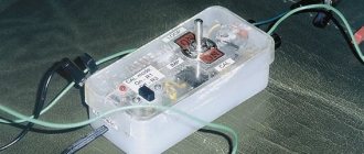
Diagram of a box for measuring speaker parameters.
It consists of two connectors for a computer sound card, a TDA2030 broadband amplifier (3-20000Hz) with a 12 V power supply from an LED strip and a resistor divider.
The principle of operation is as follows: the Audiotester program sends a signal to the speaker, the voltage difference before and after the 10 ohm resistor is measured, and the speaker coil resistance to alternating current is calculated. Experiments have shown that more accurate data on the total quality factor are obtained when measuring from 3Hz. To determine the equivalent volume, we use the additional mass method or assemble a sealed box. The photo shows a diagram of the box of my version, an example of the impedance of a subwoofer speaker and a photo of the box itself.
The use of an amplifier makes it possible to produce parameters at a power of about 1 watt, while the accuracy increases significantly.
The measurements were carried out using the built-in Realtek codec, it measures accurately.
Calibration:
First you need to calibrate the voltmeter. To do this, instead of a speaker, a 10 Ohm resistance is connected and by selecting the voltage supplied by the generator, it is necessary to achieve a voltage of 0.01 volts. If the resistor is of a different value, then the voltage should correspond to 1/1000 of the resistance value in Ohms. For example, for a 4 ohm calibration resistance, the voltage should be 0.004 volts.
Remember! After calibration, the generator output voltage cannot be adjusted until all measurements are completed.
What size is optimal?
If your car has front-facing speakers, then it is optimal to use a 16-centimeter speaker. This diameter will allow you to achieve good sound with low bass. As a rule, speakers with this diameter can be installed in a car without problems, but in some cases the installation space may be smaller. In practice, this problem can be solved on your own or by turning to specialists at the installation center for help. It is only necessary to slightly increase the size of the standard space for mounting the loudspeaker (the author of the video is URAL Sound Russia - Official Channel).
It is worth considering one main feature that many of our compatriots neglect, in particular, we are talking about the differences between models of the same line. We are talking about speaker models characterized by advanced technical features. It should be noted that the cost of different models may not vary much.
If your vehicle is equipped with three-component acoustics, then the best option would be to use 20 cm speakers. They are especially suitable for reproducing mid-frequency ranges due to their size. However, it is the dimensions that are the main problem that may cause difficulties in installing loudspeakers, especially in the front of the car. Not so often, but still such speakers are used for two-component acoustic systems; in this case, it must be taken into account that the quality of mid-frequency playback leaves much to be desired. As practice shows, 20-centimeter speakers are most optimally suited for systems that do not have a subwoofer.
Finding the resonant frequency of the speaker Fs and Rmax
The speaker during this and all subsequent measurements must be in free space. The resonant frequency of a speaker is found at the peak of its impedance (Z-characteristic). To find it, smoothly change the frequency of the generator and look at the voltmeter readings.
The frequency at which the voltage Us on the voltmeter will be maximum (a further change in frequency will lead to a voltage drop) will be the main resonance frequency Fs for this speaker. For speakers with a diameter greater than 16 cm, this frequency should be below 100 Hz.
Don't forget to record not only the frequency Fs, but also the voltmeter readings Us.
Multiplied by 1000, they will give the speaker resistance at the resonant frequency Rmax, necessary for calculating other parameters.
Parameters (Fs, Qts, Vas)
Fs - speaker resonant frequency
Resonant frequency (Fs) - the resonance frequency of a subwoofer without acoustic design (without housing).
Fs less than 25 Hz is considered low, and more than 40 Hz is considered high. The resonant frequency depends on the overall rigidity of the subwoofer suspension and the mass of its moving system. The overall rigidity, in turn, depends on the rigidity of the centering washer and the rigidity of the diffuser suspension.
Spoiler
Fs - resonant frequency of the speaker, Hz
,
Where:
Сms - flexibility of suspension of the moving speaker system, m/N,
Mms - mass of the moving system (including mass of moving air), kg.
Qts - full quality factor
Total quality factor (Qts) is the elasticity (control) of the speaker around the resonant frequency (Fs) .
In other words, the higher the quality factor, the more the sub “wobbles” in the region of its resonant frequency (Fs) , and the lower it is, the more effectively the oscillations are damped (controlled).
It consists of mechanical quality factor , which depends mainly on the material of the centering washer, and not the diffuser suspension, as many people think, and electrical quality , which depends on the size of the magnet, the length of the coil winding and the width of the gap in the magnetic system. Of the total quality factor, mechanical is 10-15%, and electrical is 90-85%, respectively.
Low quality factor is considered to be 0.3-0.35, high - 0.5-0.6.
Spoiler
Qts is the total quality factor at frequency Fs , , where:
- Qms - mechanical quality factor at frequency Fs ,
,
Fs - resonant frequency of the speaker, Hz,
Mms - mass of the moving system (including mass of moving air), kg,
Rms - mechanical resistance of the suspension of the moving system (determines the “losses” in the suspension), N s/m,
- Qes is the electrical quality factor at frequency Fs ,
,
Mms - mass of the moving system (including mass of moving air), kg,
Fs is the resonant frequency of the speaker, Hz,
Re - voice coil resistance, Ohm,
Bl is the electromechanical coupling coefficient (field induction in the magnetic gap multiplied by the length of the voice coil wire), T m.
Vas - equivalent volume
Equivalent volume (Vas) is the volume of air in the enclosure that has the same elasticity as the subwoofer. Depends on the rigidity of the suspension and the diffuser area (diameter) of the speaker.
The larger the diameter and softer the subwoofer, the greater Vas .
It should be noted the peculiarity of the connection between Vas and Fs . Since the resonant frequency (Fs) is determined by the rigidity of the suspension and the mass of the moving system, and the equivalent volume (Vas) is determined by the diameter of the diffuser and the same moving mass, it may turn out that two subwoofers of the same diameter and with the same Fs will be completely different - one heavy and hard, the other light and soft. Accordingly, the equivalent volume for these speakers will be completely different, as well as the size of the correct enclosure - which is why this parameter is very important when calculating a box for a subwoofer.
Spoiler
Vas - equivalent volume, l,
,
Where:
- ρ — 1.18421 kg/m³ — air density at a temperature of 25 °C and humidity 0%,
- s - 346.1 m/s - speed of sound at 25 °C,
- Sd —diffuser area, m.
Video
Use the Thiel-Small parameters to design your subwoofer enclosure. Use these parameters to correctly select the type of subwoofer enclosure (ZYA, FI, CHV, FreeAir) or to select a speaker for the intended type, read how to do this correctly here.
Finding Qms, Qes and Qts
These parameters are found using the following formulas:
Rice. 2. Formulas for measuring Thiel-Small parameters
As you can see, this is a sequential finding of additional parameters Ro, Rx and measurement of previously unknown frequencies F1 and F2.
Rice. 3. Graph of DC resistance versus resonant frequency
These are the frequencies at which the speaker impedance is equal to Rx. Since Rx is always less than Rmax, there will be two frequencies - one is slightly less than Fs, and the other is slightly more.
The frequencies F1 and F2 are determined below and above the resonant frequency Fs, at which the voltage at the head terminals takes on a certain value U1.2, less than Us. For example, U1,2 = 0.7 Us. You can check the accuracy of your measurements with the following formula:
Rice. 4. Formula for calculating the resonant frequency of the speaker
If the calculated result differs from the previously found one by more than 1 hertz, then you need to repeat everything all over again and more carefully. So, we have found and calculated several basic parameters and can draw some conclusions based on them:
- If the resonant frequency of the speaker is above 50 Hz, then it has the right to claim to work, at best, as a midbass. You can immediately forget about the subwoofer on such a speaker.
- If the resonant frequency of the speaker is above 100 Hz, then it is not a woofer at all. You can use it to reproduce mid frequencies in three-way systems.
- If a speaker's Fs/Qts ratio is less than 50, then that speaker is designed to operate exclusively in closed boxes. If more than 100 - exclusively for working with a bass reflex or in bandpasses. If the value is between 50 and 100, then you need to carefully look at other parameters - what type of acoustic design the speaker gravitates towards. It is best to use special computer programs for this that can graphically simulate the acoustic output of such a speaker in different acoustic designs. True, you cannot do without other, no less important parameters - Vas, Sd, Cms and L.
Thiel-Small parameters: three acoustic maps. Magazine "Avtozvuk"
Today we will talk about what is really important to know about acoustics. Namely, about the famous Thiel-Small parameters, knowledge of which is the key to winning in the gambling game of sound.
Save and read later -
- How! Do you have a grandmother who guesses three cards in a row, and you still haven’t learned her cabalistics from her? A.S. Pushkin, "The Queen of Spades"
Today we will talk about what is really important to know about acoustics. Namely, about the famous Thiel-Small parameters, knowledge of which is the key to winning in the gambling game of car audio. Without defamation and cabalism.
One outstanding mathematician, according to legend, while lecturing to students, said: “And now we will begin to prove the theorem whose name I have the honor to bear.” Who had the honor of bearing the names of Thiel and Small's parameters? Let's remember this too. The first in the bunch is Albert Neville Thiele (in the original A. Neville Thiele, “A” is almost never deciphered). Both by age and bibliography. Thiel is now 84 years old, and when he was 40, he published a landmark paper that pioneered the ability to calculate loudspeaker performance using a single set of parameters in a convenient and repeatable manner.
There, in a 1961 paper, it was said, in part, “The low-frequency performance of a loudspeaker can be adequately described by three parameters: the resonant frequency, the volume of air equivalent to the acoustic flexibility of the loudspeaker, and the ratio of electrical resistance to resistance to movement at the resonant frequency The same parameters are used to determine electroacoustic efficiency. I encourage loudspeaker manufacturers to publish these parameters as part of the basic information about their products."
Neville Thiel's request was heard by the industry only a decade later, at which time Thiel was already working with Richard Small, a native of California. Richard Small is spelled in Californian, but for some reason the respected doctor prefers the German pronunciation of his own name. Small turns 70 this year, which, by the way, is a more important anniversary than most. In the early seventies, Thiel and Small finally finalized their proposed approach to calculating loudspeakers.
Neville Thiel is now a professor emeritus at a university in his home country of Australia, and Dr. Small's last professional position that we were able to track was as chief engineer of Harman-Becker's automotive audio department. And, of course, both are members of the leadership of the International Society of Acoustic Engineers (Audio Engineering Society). In general, both are alive and well.
Thiel on the left, Small on the right, in order of contribution to electroacoustics. By the way, the photo is rare, the masters did not like to be photographed
To hang or not to hang?
The figurative definition of the conditions for measuring Fs as the resonant frequency of a speaker hanging in the air gave rise to the misconception that this is how this frequency should be measured, and enthusiasts actually tried to hang speakers on wires and ropes. A separate issue of “BB”, or even more than one, will be devoted to measuring acoustic parameters, but I’ll note here: in competent laboratories, speakers are clamped in a vice during measurements, and not suspended from a chandelier.
The results of a computational experiment that will help those wishing to understand how the values of electrical and mechanical quality factor are expressed in impedance curves. We took the full set of electromechanical parameters of a real-life speaker, and then began to change some of them. First, the mechanical quality, as if the material of the corrugation and the centering washer had been replaced. Then - electric, for this it was necessary to change the characteristics of the drive and the moving system. Here's what happened:
Real impedance curve of a woofer. It calculates two of the three main parameters
Impedance curves for different values of the total quality factor, while the electrical Qes is the same, equal to 0.5, and the mechanical one varies from 1 to 8. The total quality factor Qts does not seem to change much, but the height of the hump on the impedance graph changes greatly and very , while the lower the Qms, the sharper it becomes
Dependence of sound pressure on frequency at the same Qts values. When measuring sound pressure, only the total quality factor Qts is important, so completely different impedance curves correspond to not so different sound pressure curves versus frequency
The same Qts values, but now Qms = 4 everywhere, and Qes changes so as to reach the same Qts values. The Qts values are the same, but the curves are completely different and differ much less from each other. The lower, red curves were obtained for those values that could not be obtained in the first experiment at a fixed Qes = 0.5
Sound pressure curves for different Qts obtained by changing Qes. The four upper curves are exactly the same in shape as when we changed Qms, their shape is determined by the Qts values, but they remain the same. The lower, red curves obtained for Qts greater than 0.5 are, of course, different, and a hump begins to grow on them due to the increased quality factor.
Now pay attention: the point is not only that at high Qts a hump appears on the characteristic, and the sensitivity of the speaker at frequencies above the resonant one decreases. The explanation is simple: other things being equal, Qes can only increase with an increase in the mass of the moving system or with a decrease in the magnet power. Both lead to a decrease in sensitivity at mid frequencies. So the hump at the resonant frequency is, rather, a consequence of the dip at frequencies above the resonant one. There is nothing free in acoustics...
Junior partner contribution
By the way: the founder of the method A.N. Thiel intended to take into account only the electrical quality factor in the calculations, believing (correctly for his time) that the share of mechanical losses was negligible compared to the losses caused by the operation of the “electric brake” of the speaker. The junior partner's contribution, however, was not the only one, however, was taking into account Qms, this has now become important: modern drivers use materials with increased losses that did not exist in the early 60s, and we came across speakers where the Qms value was only 2 - 3, with electric under unit. In such cases, it would be a mistake not to take mechanical losses into account. And this became especially important with the introduction of ferrofluid cooling in RF heads, where, due to the damping effect of the liquid, the Qms share in the total quality factor becomes decisive, and the impedance peak at the resonance frequency becomes almost invisible, as in the first graph of our computational experiment.
Three cards revealed by Thiel and Small
1. Fs - the main resonance frequency of the speaker without any housing. Characterizes only the speaker itself, and not the finished speaker system based on it. When installed in any volume it can only increase.
2. Qts is the total quality factor of the speaker, a dimensionless quantity that characterizes the relative losses in the dynamics. The lower it is, the more the radiation resonance is suppressed and the higher the resistance peak on the impedance curve. Increases when installed in a closed box.
3. Vas - equivalent speaker volume. Equal to the volume of air with the same rigidity as the suspension. The stiffer the suspension, the less Vas. At the same stiffness, Vas increases with increasing diffuser area.
Two halves making up card No. 2
1. Qes - the electrical component of the total quality factor, characterizes the power of the electric brake, which prevents the diffuser from swinging near the resonant frequency. Typically, the more powerful the magnetic system, the stronger the “brake” and the smaller the numerical value of Qes.
2. Qms - the mechanical component of the total quality factor, characterizes the losses in the elastic elements of the suspension. The losses here are much smaller than in the electrical component, and Qms is numerically much larger than Qes.
How long does the bell ring?
What do a bell and a loudspeaker have in common? Well, the fact that both sound is obvious. More importantly, both are oscillatory systems. What's the difference? The bell, no matter how you strike it, will sound at the only frequency prescribed by the canon. And outwardly, the speaker is not so different from it - in a wide range of frequencies, and can, if desired, simultaneously depict both the ringing of a bell and the puffing of a bell-ringer. So: two of the three Thiel-Small parameters precisely describe this difference quantitatively.
You just need to firmly remember, or better yet, re-read the quote from the founder in the historical and biographical note. It says “at low frequencies.” Thiel, Small and their parameters have nothing to do with how the speaker behaves at higher frequencies and do not bear any responsibility for this. Which speaker frequencies are low and which are not? And this is what the first of the three parameters speaks about.
Map one, measured in hertz
So: Thiel-Small parameter No. 1 is the speaker’s own resonant frequency. It is always designated Fs, regardless of the language of publication. The physical meaning is extremely simple: since the speaker is an oscillating system, it means there must be a frequency at which the diffuser will oscillate when left to its own devices. Like a bell after being struck or a string after being plucked. This means that the speaker is absolutely “naked”, not installed in any housing, as if hanging in space. This is important because we are interested in the parameters of the speaker itself, and not of what surrounds it.
The range of frequencies around the resonant one, two octaves up, two octaves down - this is the area where the Thiel-Small parameters operate. For subwoofer heads that have not yet been installed in the housing, Fs can range from 20 to 50 Hz, for midbass speakers from 50 (bass “sixes”) to 100 - 120 (“fours”). For diffuser mid-frequencies - 100 - 200 Hz, for domes - 400 - 800, for tweeters - 1000 - 2000 Hz (there are exceptions, very rare).
How is the natural resonant frequency of a speaker determined? No, as is most often defined - clearly, read in the accompanying documentation or in the test report. Well, how was she initially recognized? It would be easier with a bell: hit it with something and measure the frequency of the buzz produced. The speaker will not hum explicitly at any frequency. That is, he wants to, but the damping of diffuser vibrations inherent in his design does not allow him to do so. In this sense, the speaker is very similar to a car suspension, and I have used this analogy more than once and will continue to do so. What happens if you rock a car with empty shock absorbers? It will swing at least a few times at its own resonant frequency (where there is a spring, there will be a frequency). Shock absorbers that are only partially dead will stop the oscillations after one or two periods, while those that are in good working order will stop after the first swing. In dynamics, the shock absorber is more important than the spring, and here there are even two of them.
The first, weaker one, works due to the fact that energy is lost in the suspension. It is no coincidence that the corrugation is made from special types of rubber; a ball made of such material will hardly bounce off the floor; a special impregnation with high internal friction is also chosen for the centering washer. This is like a mechanical brake of diffuser vibrations. The second, much more powerful, is electric.
Here's how it works. The speaker's voice coil is its motor. An alternating current flows through it from the amplifier, and the coil, located in a magnetic field, begins to move with the frequency of the supplied signal, moving, of course, the entire moving system, then it is here. But a coil moving in a magnetic field is a generator. Which will generate more electricity the more the coil moves. And when the frequency begins to approach the resonant one, at which the diffuser “wants” to oscillate, the amplitude of the oscillations will increase, and the voltage produced by the voice coil will increase. Reaching a maximum exactly at the resonant frequency. What does this have to do with braking? None yet. But imagine that the coil leads are connected to each other. Now a current will flow through it and a force will arise, which, according to Lenz’s school rule, will impede the movement that generated it. But in real life the voice coil is closed to the output impedance of the amplifier, which is close to zero. It turns out like an electric brake that adapts to the situation: the more the diffuser tries to move back and forth, the more the counter current in the voice coil prevents this. The bell has no brakes, except for the damping of vibrations in its walls, and in bronze - what damping...
The second map, not measured in anything
The brake power of a speaker is numerically expressed in the second Thiel-Small parameter. This is the total quality factor of the speaker, designated Qts. Expressed numerically, but not literally. I mean, the more powerful the brakes, the lower the Qts value. Hence the name “quality factor” in Russian (or quality factor in English, from which the designation of this quantity originated), which is, as it were, an assessment of the quality of the oscillatory system. Physically, the quality factor is the ratio of elastic forces in a system to viscous forces, otherwise - to friction forces. Elastic forces store energy in the system, alternately transferring energy from potential (a compressed or stretched spring or speaker suspension) to kinetic (the energy of a moving diffuser). Viscous ones strive to turn the energy of any movement into heat and irrevocably dissipate. A high quality factor (and for the same bell it will be measured in tens of thousands) means that there are much more elastic forces than frictional forces (viscous, these are the same thing). This also means that for each oscillation only a small part of the energy stored in the system will be converted into heat. Therefore, by the way, quality factor is the only value in the three Thiel-Small parameters that does not have a dimension; it is the ratio of one force to another. How does a bell dissipate energy? Through internal friction in bronze, mainly slowly. How does a speaker do this, whose quality factor is much lower, and therefore the rate of energy loss is much higher? In two ways, depending on the number of “brakes”. Part is dissipated through internal losses in the elastic elements of the suspension, and this share of losses can be estimated by a separate value of the quality factor, it is called mechanical, denoted Qms. The second, larger part is dissipated in the form of heat from the current passing through the voice coil. The current produced by her. This is the electrical quality factor Qes. The total effect of the brakes would be determined very easily if it were not the values of the quality factor, but, on the contrary, the values of losses that were used. We would just fold them. And since we are dealing with quantities that are the reciprocals of losses, then we will have to add the reciprocal quantities, which is why it turns out that 1/Qts = 1/Qms + 1/Qes.
Typical values of quality factor: mechanical - from 5 to 10. Electrical - from 0.2 to 1. Since inverse values are involved, it turns out that we sum up the mechanical contribution to losses of the order of 0.1 - 0.2 with the electrical contribution, which is from 1 to 5. It is clear that the result will be determined mainly by the electrical quality factor, that is, the main brake of the speaker is electric.
So how do you snatch the names of the “three cards” from the speaker? Well, at least the first two, we'll get to the third. It is useless to threaten with a pistol, like Hermann, the speaker is not an old woman. The same voice coil, the fiery speaker motor, comes to the rescue. After all, we have already realized: a flame motor also works as a flame generator. And in this capacity, it seems to be sneaking about the amplitude of vibrations of the diffuser. The greater the voltage appears on the voice coil as a result of its oscillations together with the diffuser, the greater the range of oscillations, which means the closer we are to the resonant frequency.
How to measure this voltage, given that a signal from the amplifier is connected to the voice coil? That is, how to separate what is supplied to the motor from what is generated by the generator, is it on the same terminals? You don’t need to divide, you need to measure the resulting amount.
This is why they do this. The speaker is connected to an amplifier with the highest possible output impedance; in real life, this means: a resistor with a value of much, one hundred, at least, times the nominal resistance of the speaker is connected in series with the speaker. Let's say 1000 ohms. Now, when the speaker is operating, the voice coil will generate a back-EMF, sort of like for the operation of an electric brake, but braking will not occur: the coil leads are closed to each other through a very high resistance, the current is negligible, the brake is useless. But the voltage, according to Lenz’s rule, is opposite in polarity to the supplied one (“generating movement”), will be in antiphase with it, and if at this moment you measure the apparent resistance of the voice coil, it will seem that it is very large. In fact, in this case, the back-EMF does not allow the current from the amplifier to flow unhindered through the coil, the device interprets this as increased resistance, but what else?
By measuring the impedance, that very “apparent” (but in fact complex, with all sorts of active and reactive components, now is not the time to talk about that) resistance, two cards out of three are revealed. The impedance curve of any cone speaker, from Kellogg and Rice to the present day, looks, in principle, the same, it even appears in the logo of some electroacoustic scientific community, I forget which one now. The hump at low (for this speaker) frequencies indicates the frequency of its fundamental resonance. Where there is a maximum, there is the coveted Fs. It couldn't be more elementary. Above resonance there is a minimum impedance, which is usually taken as the nominal impedance of the speaker, although, as you can see, it remains this way only in a small frequency band. Higher up, the total resistance begins to increase again, now due to the fact that the voice coil is not only a motor, but also an inductance, the resistance of which increases with frequency. But we won’t go there now; the parameters that interest us don’t live there.
It is much more complicated with the value of the quality factor, but, nevertheless, comprehensive information about the “second card” is also contained in the impedance curve. Comprehensive, because from one curve you can calculate both the electrical Qes and the mechanical quality factor Qms, separately. We already know how to then make a complete Qts out of them, which is really necessary when calculating the design; it’s a simple matter, not a Newton binomial.
We will discuss exactly how the required values are determined from the impedance curve another time, when we talk about methods for measuring parameters. Now we will assume that someone (the speaker manufacturer or the associates of your humble servant) did this for you. But I will note this. There are two misconceptions associated with attempts to expressly analyze the Thiel-Small parameters based on the shape of the impedance curve. The first is completely bogus, and we will now dispel it without a trace. This is when they look at the impedance curve with a huge hump at resonance and exclaim: “Wow, good quality!” Kind of high. And looking at the small bump on the curve, they conclude: since the impedance peak is so smooth, it means that the speaker has high damping, that is, a low quality factor.
So: in the simplest version, it’s exactly the opposite. What does a high impedance peak at resonance frequency mean? That the voice coil produces a lot of back-EMF, designed to electrically brake the oscillations of the cone. Only with this connection, through a large resistance, the current necessary for the operation of the brake does not flow. And when such a speaker is turned on not for measurements, but normally, directly from the amplifier, the braking current will flow, be healthy, the coil will become a powerful obstacle to the excessive oscillations of the diffuser at its favorite frequency.
All other things being equal, you can roughly estimate the quality factor from the curve, and remembering: the height of the impedance peak characterizes the potential of the speaker's electric brake, therefore, the higher it is, the LOWER the quality factor. Will such an assessment be exhaustive? Not exactly, as was said, she will remain rude. Indeed, in the impedance curve, as already mentioned, information about both Qes and Qms is buried, which can be dug out (manually or using a computer program) by analyzing not only the height, but also the “shoulder width” of the resonant hump.
And how does the quality factor affect the shape of the speaker’s frequency response? This is what interests us, isn’t it? How it affects - it has a decisive impact. The lower the quality factor, that is, the more powerful the internal brakes of the speaker at the resonant frequency, the lower and more smoothly the curve will pass near the resonance, characterizing the sound pressure created by the speaker. The minimum ripple in this frequency band will be at Qts equal to 0.707, which is commonly called the Butterworth characteristic. At high Q values, the sound pressure curve will begin to “hump” near resonance, it’s clear why: the brakes are weak.
Is there a “good” or a “bad” total quality factor? By itself, no, because when the speaker is installed in an acoustic design, which we will now consider only a closed box, both its resonance frequency and overall quality factor will become different. Why? Because both depend on the elasticity of the speaker suspension. The resonant frequency depends only on the mass of the moving system and the rigidity of the suspension. As stiffness increases, Fs increases, and as mass increases, it decreases. When the speaker is installed in a closed box, the air in it, which has elasticity, begins to act as an additional spring in the suspension, the overall rigidity increases, Fs increases. The total quality factor also increases, since it is the ratio of elastic forces to braking forces. The brake capabilities of the speaker will not change from installing it to a certain volume (why would it?), but the total elasticity will increase, the quality factor will inevitably increase. And it will never become lower than the “naked” dynamics. Never, this is the lower limit. How much will all this increase? And this depends on how rigid the speaker’s own suspension is. Look: the same value of Fs can be obtained with a light diffuser on a soft suspension or with a heavy one on a hard suspension; mass and stiffness act in opposite directions, and the result may turn out to be numerically equal. Now if we place a speaker with a rigid suspension in some volume (which has the elasticity required for this volume), then it will not notice a slight increase in the total stiffness, the values of Fs and Qts will not change much. Let’s put a speaker with a soft suspension there, in comparison with the stiffness of which the “air spring” will already be significant, and we will see that the total stiffness has changed significantly, which means that Fs and Qts, initially the same as those of the first speaker, will change significantly.
In the dark “pre-Tile” times, in order to calculate new values of the resonance frequency and quality factor (they, in order not to be confused with the parameters of the “bare” speaker, are designated as Fc and Qtc), it was necessary to know (or measure) directly the elasticity of the suspension, in millimeters per newton of applied force , know the mass of the moving system, and then play tricks with calculation programs. Thiel proposed the concept of “equivalent volume,” that is, a volume of air in a closed box whose elasticity is equal to the elasticity of the speaker suspension. This value, designated Vas, is the third magic card.
Map three, three-dimensional
How Vas is measured is a separate story, there are funny twists, and this, as I’m saying for the third time, will be in a special issue of the series. For practice, it is important to understand two things. First: an extremely Lokhov’s misconception (alas, it still occurs) that the Vas value given in the accompanying documents for the speaker is the volume in which the speaker should be placed. And this is just a characteristic of the speaker, depending only on two quantities: the rigidity of the suspension and the diameter of the diffuser. If you put a speaker in a box with a volume equal to Vas, the resonant frequency and overall quality factor will increase by a factor of 1.4 (this is the square root of two). If in a volume equal to half Vas - 1.7 times (root of three). If you make a box with a volume of one third of Vas, everything else will double (the root of four, the logic should already be clear without formulas).
As a result, indeed, the smaller, other things being equal, the Vas value of the speaker, the more compact design you can count on, while maintaining the planned indicators for Fc and Qtc. Compactness, however, does not come for free. There is no such thing as free in acoustics. The low Vas value at the same resonant frequency of the speaker is the result of a combination of a rigid suspension with a heavy moving system. And the sensitivity most decisively depends on the mass of the “movement”. Therefore, all subwoofer heads, distinguished by the ability to operate in compact closed enclosures, are also characterized by low sensitivity compared to colleagues with lightweight diffusers but high Vas values. So there are no good or bad Vas values either, everything has its own price.
Prepared based on materials from the Avtozvuk magazine, March 2005
www.avtozvuk.com
This article was read 68,993 times
The article is included in the sections:
"Do it yourself"
Finding the diffuser surface area Sd
This is the so-called effective radiating surface of the diffuser. For the lowest frequencies (in the zone of piston action) it coincides with the design one and is equal to:
Rice. 5. Formula for calculating diffuser surface area
The radius R in this case will be half the distance from the middle of the width of the rubber suspension on one side to the middle of the rubber suspension on the opposite side. This is due to the fact that half the width of the rubber suspension is also a radiating surface. Please note that the unit of measurement for this area is square meters. Accordingly, the radius must be substituted into it in meters.
Measuring speakers at home and adjusting the bass reflex
(To help beginner bass players)
Chapter A - Measurements
Let me make a reservation right away that the most convenient way to measure the parameters of woofers is outlined in the JBL Speaker Shop
. I suggest that program owners use this method (I haven’t tested it myself, but I think there are no glitches there). For those who do not have this program or do not have enough measuring equipment, I will describe the method I learned from “RADIO” magazines of past years. I used this method, and with a certain degree of accuracy and perseverance, you can use it to get fairly accurate (more precisely than in the reference book or user manual) parameters.
So, let's begin:
1) Let's put together a diagram:
I think it’s clear where the speaker under test is in the diagram. The remaining elements of the diagram require detailed explanation.
Generator - either an audio frequency generator capable of producing a voltage of 10-20 V, or a generator-amplifier combination that satisfies the same requirement.
A 1000 Ohm resistor stabilizes the current through the speaker. The resistor value can be taken less, but this will reduce the accuracy of the Qts calculation. (True, when using a resistor of only 200 Ohms, the measurement error is unlikely to exceed 10%, but, as they say, save...).
a, b, c – points for connecting a voltmeter.
The voltmeter itself is not indicated in the figure, but it should be: - firstly, alternating current; – secondly, be able to measure voltages of the order of 100 mV. If the voltmeter does not have such a measurement limit, it can be connected through an amplifier. And since modern amplifiers are usually “stereo” or more, there are no special problems with this.
2) The circuit is assembled, we place the speaker away from the walls, ceiling and floor (it is often recommended to hang it).
3) Connect a voltmeter to points a and c, and set the voltage to 10-20 V at a frequency of 500-1000 Hz.
4) We connect a voltmeter to points b and c, and by changing the frequency of the generator we find the frequency at which the voltmeter readings are maximum, see the figure below in the text. This is Fs. We record the Fs and Us readings of the voltmeter.
5) By changing the frequency upward relative to Fs, we find frequencies at which the voltmeter readings are constant and significantly less than Us (with a further increase in frequency, the voltage will begin to increase again, in proportion to the increase in speaker impedance). Let's write down this value, Um.
A graph of speaker impedance in free space and in a closed box looks something like this:
6) Find it from the graph (if we built it) or measure the cutoff frequencies F1 and F2 at the level U12=(Us*Um)^0.5;
7) Calculate the acoustic quality factor Qa=(Us/Um)^0.5*Fs/(F2-F1), and
Electrical quality factor Qe=Qa*Um/(Us-Um);
9) And, finally, the total quality factor Qts=Qa*Qe/(Qa+Qe).
To find out Vas, we need a box (a good sealed box, by no means cardboard, but with thick walls) with a round hole that matches the diameter of the speaker cone. It is better to choose the volume of the box, V, closer to the one in which we are then going to listen to this speaker.
10) Install the speaker in the box and seal all the cracks;
11) We carry out all measurements and calculations according to points 1)-6) and obtain the values of Fs' (actually this is Fc) and Qts' (Qtc);
12) Calculate Vas=((Fs'/Fs)^2-1)*V;
13) We calculate Qtc=Qts*(1+Vas/V)^0.5, if the measured Qts'=Qtc is well or almost equal, then everything is done correctly, and you can proceed to designing the acoustic system.
Chapter B – FI Setup
The proposed setup method is also copied from the Literature, but is simple enough to become the property of the curious masses. The only caveat (I came up with it myself) is that this technique allows you to easily tune FIs made on the basis of speakers with a quality factor of Qts = 0.3...0.5. For other FIs, you will have to additionally use your natural ingenuity. So.
The methodology is based on the relationship that exists between the parameters of the FI and the closed box (closed box). If in a FI with a smooth frequency response (according to spl) the tunnel hole is closed, then the total quality factor of the system, Qtc, will be equal to 0.6, and the resonant frequency, Fc, will be related to the FI tuning frequency by the dependence: Fb=0.61…0.65*Fc. If we allow an error in determining the FI tuning frequency of 5%, then the Fb/Fc ratio for real structures can be taken equal to 0.63.
Setting:
14) We close the tunnel hole hermetically and assemble a circuit for measuring Fc (see chapter A).
15) We select the amount of sound-absorbing material and achieve the minimum Fc value;
16) We fix the material inside the box and measure Fc;
17) Calculate Fb=0.63*Fc;
18) Calculate the length of the tunnel: Lv=31*10^3*S/(Fb^2*V)-1.7*(S/PI)^0.5, where S is the area of the FI port opening in sq. cm., V – volume of the box in liters;
19) We make a tunnel, insert it inside the box (inside, if in the finished design it is supposed to be inside) and measure Fb'.
It should look something like:
20) We substitute the resulting value Fb' into formula 18) and calculate the adjusted value V';
21) Substitute V' into formula 18) and calculate Lv' for the calculated value of Fb (who forgot, this happened in step 17);
22) We shorten (it is impossible to lengthen it, so it is better to take measures in advance) the tunnel and measure again;
23) Using the method for determining Qtc (Chapter A), we determine the quality factor of the system and, if it is less than 1, we calm down. If it is larger, then something was probably done wrong somewhere, but it’s too late to redo it. Let's listen, if he really mumbles (which is not at all necessary), we will take action.
Possible measures:
24) Dampen the FI tunnel with a partially acoustically transparent material. In other words, close the tunnel with padding polyester, cotton wool, carpet, etc.;
25) Dampen the speaker itself by gluing the materials listed above to the windows of the diffuser holder (but not all at once).
These measures will reduce the overall quality factor of the system, Qtc.
Literature:
Saltykov O., Calculation of loudspeaker characteristics, Radio 1981
Zhbanov V., Setting up the bass reflex, Radio 8/1986
Aldoshina I. Where the basses live, AM 2/1999
Frunze, On improving the sound quality of speakers, Radio 9/1992
Finding the inductance of the speaker coil L
To do this, you need the results of one of the readings from the very first test. You will need an impedance (impedance) of the voice coil at a frequency of about 1000 Hz. Since the reactive component (XL) is separated from the active Re by an angle of 900, we can use the Pythagorean theorem:
Rice. 6. Formula for coil impedance at a certain frequency
Since Z (coil impedance at a certain frequency) and Re (coil DC resistance) are known, the formula converts to:
Rice. 7. Formula for coil impedance at a certain frequency
Having found the reactance XL at frequency F, you can calculate the inductance itself using the formula:
Rice. 8. Coil inductance formula
Measurement of equivalent volume Vas
There are several ways to measure equivalent volume, but at home it is easier to use two: the “additional mass” method and the “additional volume” method.
The first of them requires several weights of known weight from materials. You can use a set of weights from pharmacy scales or use old copper coins of 1,2,3 and 5 kopecks, since the weight of such a coin in grams corresponds to the face value.
The second method requires a sealed box of a predetermined volume with a corresponding hole for the speaker.
Finding Vas using the added mass method
First you need to evenly load the diffuser with weights and measure its resonant frequency again, writing it down as F's. It should be lower than Fs. It is better if the new resonant frequency is 30% -50% less. The weights are approximately 10 grams per inch of diffuser diameter. Those. for a 12″ head you need a load weighing about 120 grams.
Then you need to calculate Cms based on the results obtained using the formula:
Rice. 9. Formula for calculating relative stiffness
where M is the mass of added weights in kilograms.
Based on the results obtained, Vas(m3) is calculated using the formula:
Rice. 9. Formula for calculating equivalent volume
Finding Vas using the additional volume method
It is necessary to seal the speaker in the measuring box. It is best to do this with the magnet facing out, since the speaker does not care which side it has volume on, and it will be easier for you to connect the wires. And there are fewer extra holes. The volume of the box is designated as Vb.
Then you need to measure Fc (the resonant frequency of the speaker in a closed box) and, accordingly, calculate Qmc, Qec and Qtc. The measurement technique is completely similar to that described above. Then the equivalent volume is found using the formula:
Rice. 10. Formula for calculating equivalent volume using the additional volume method
The data obtained as a result of all these measurements is sufficient for further calculation of the acoustic design of a low-frequency link of a sufficiently high class. But how it is calculated is a completely different story.
Installers website
The most basic parameters by which a subwoofer can be calculated and manufactured are:
- Speaker Resonance Frequency Fs (Hertz)
- Equivalent volume Vas (liters or cubic feet)
- Full Qts
- DC resistance Re (Ohm)
For a more serious approach, you will also need to know:
- Mechanical quality factor Qms
- Electrical quality factor Qes
- Diffuser area Sd (m2) or diameter Dia (cm)
- Sensitivity SPL (dB)
- Inductance Le (Henry)
- Impedance Z (Ohm)
- Peak power Pe (Watt)
- Mass of the moving system Mms (g)
- Relative hardness Cms (meters/newton)
- Mechanical resistance Rms (kg/sec)
- Motor power BL
Most of these parameters can be measured or calculated at home using not particularly sophisticated measuring instruments and a computer or calculator that can extract roots and exponentiate. For an even more serious approach to designing acoustic design and taking into account the characteristics of speakers, I recommend reading more serious literature. The author of this “work” does not claim any special knowledge in the field of theory, and everything presented here is a compilation from various sources - both foreign and Russian.
Measurement of Re, Fs, Fc, Qes, Qms, Qts, Qtc, Vas, Cms, Sd.
To measure these parameters you will need the following equipment:
- Voltmeter
- Audio signal generator
- Frequency meter
- Powerful (at least 5 watts) resistor with a resistance of 1000 ohms
- Accurate (+- 1%) 10 ohm resistor
- Wires, clamps and other rubbish to connect it all into a single circuit.
Of course, this list is subject to change. For example, most generators have their own frequency scale and a frequency meter is not necessary in this case. Instead of a generator, you can also use a computer sound card and corresponding software capable of generating sinusoidal signals from 0 to 200 Hz of the required power.
Measurement of Thiel-Small parameters
Scheme for measurements
Calibration:
First you need to calibrate the voltmeter. To do this, instead of a speaker, a 10 Ohm resistance is connected and by selecting the voltage supplied by the generator, it is necessary to achieve a voltage of 0.01 volts. If the resistor is of a different value, then the voltage should correspond to 1/1000 of the resistance value in ohms. For example, for a 4 ohm calibration resistance, the voltage should be 0.004 volts. Remember! After calibration, the generator output voltage cannot be adjusted until all measurements are completed.
Finding Re
Now, by connecting a speaker instead of a calibration resistance and setting the frequency on the generator to close to 0 hertz, we can determine its resistance to direct current Re. It will be the voltmeter reading multiplied by 1000. However, Re can be measured directly with an ohmmeter.
Finding Fs and Rmax
The speaker during this and all subsequent measurements must be in free space. The resonant frequency of a speaker is found at the peak of its impedance (Z-characteristic). To find it, smoothly change the frequency of the generator and look at the voltmeter readings. The frequency at which the voltage on the voltmeter will be maximum (a further change in frequency will lead to a voltage drop) will be the main resonance frequency for this speaker. For speakers with a diameter greater than 16cm, this frequency should be below 100Hz. Don't forget to record not only the frequency, but also the voltmeter readings. Multiplied by 1000, they will give the speaker resistance at the resonant frequency Rmax, necessary for calculating other parameters.
Finding Qms, Qes and Qts
These parameters are found using the following formulas:
Finding Qms, Qes and Qts
As you can see, this is a sequential finding of additional parameters Ro, Rx and measurement of previously unknown frequencies F1 and F2. These are the frequencies at which the speaker impedance is equal to Rx. Since Rx is always less than Rmax, there will be two frequencies - one is slightly less than Fs, and the other is slightly more. You can check the accuracy of your measurements with the following formula:
If the calculated result differs from the previously found one by more than 1 hertz, then you need to repeat everything all over again and more carefully.
So, we have found and calculated several basic parameters and can draw some conclusions based on them:
- If the resonant frequency of the speaker is above 50Hz, then it has the right to claim to work, at best, as a midbass. You can immediately forget about the subwoofer on such a speaker.
- If the resonant frequency of the speaker is above 100Hz, then it is not a woofer at all. You can use it to reproduce mid frequencies in three-way systems.
- If a speaker's Fs/Qts ratio is less than 50, then that speaker is designed to operate exclusively in closed boxes. If more than 100 - exclusively for working with a bass reflex or in bandpasses. If the value is between 50 and 100, then you need to carefully look at other parameters - what type of acoustic design the speaker gravitates towards. It is best to use special computer programs for this that can graphically simulate the acoustic output of such a speaker in different acoustic designs. True, you cannot do without other, no less important parameters - Vas, Sd, Cms and L.
Finding Sd
This is the so-called effective radiating surface of the diffuser. For the lowest frequencies (in the zone of piston action) it coincides with the design one and is equal to:
Finding Sd
The radius R in this case will be half the distance from the middle of the width of the rubber suspension on one side to the middle of the rubber suspension on the opposite side. This is due to the fact that half the width of the rubber suspension is also a radiating surface. Please note that the unit of measurement for this area is square meters. Accordingly, the radius must be substituted into it in meters.
Finding the inductance of the speaker coil L
To do this, you need the results of one of the readings from the very first test. You will need an impedance (impedance) of the voice coil at a frequency of about 1000 Hz. Since the reactive component (XL) is separated from the active Re by an angle of 900, we can use the Pythagorean theorem:
Finding the inductance of the speaker coil L
Since Z (coil impedance at a certain frequency) and Re (coil DC resistance) are known, the formula converts to:
Having found the reactance XL at frequency F, you can calculate the inductance itself using the formula:
Finding the inductance of the speaker coil L
Vas measurements
There are several ways to measure equivalent volume, but at home it is easier to use two: the “additional mass” method and the “additional volume” method. The first of them requires several weights of known weight from materials. You can use a set of weights from pharmacy scales or use old copper coins of 1,2,3 and 5 kopecks, since the weight of such a coin in grams corresponds to the face value. The second method requires a sealed box of a predetermined volume with a corresponding hole for the speaker.
Finding Vas using the added mass method
First you need to evenly load the diffuser with weights and measure its resonant frequency again, writing it down as F's. It should be lower than Fs. It is better if the new resonant frequency is 30% -50% less. The weights are approximately 10 grams per inch of diffuser diameter. Those. for a 12″ head you need a load weighing about 120 grams.
Then you need to calculate Cms based on the results obtained using the formula:
Finding Vas using the added mass method
where M is the mass of added weights in kilograms.
Based on the results obtained, Vas(m3) is calculated using the formula:
Finding Vas using the added mass method
Finding Vas using the additional volume method
It is necessary to seal the speaker in the measuring box. It is best to do this with the magnet facing out, since the speaker does not care which side it has volume on, and it will be easier for you to connect the wires. And there are fewer extra holes. The volume of the box is designated as Vb.
Then you need to measure Fc (the resonant frequency of the speaker in a closed box) and, accordingly, calculate Qmc, Qec and Qtc. The measurement technique is completely similar to that described above. Then the equivalent volume is found using the formula:
Finding Vas using the additional volume method
You can use a simpler formula with almost the same results:
Finding Vas using the additional volume method
The data obtained as a result of all these measurements is sufficient for further calculation of the acoustic design of a low-frequency link of a sufficiently high class. But how it is calculated is a completely different story...
Files:
| Measuring Thiel-Small parameters A program for measuring Thiel-Small parameters of a subwoofer | 284.27 KB |
| Audio frequency generator Audio frequency generator. A convenient generator option for measuring Thiel-Small parameters of low-frequency speakers. | 21 KB |