Thiel-Small parameters... What are these parameters and what is their significance?
Briefly about the authors: Albert Neville Thiel in the early sixties of the last century proposed calculating the characteristics of dynamic heads based on a single set of parameters (hence the name). He identified three main parameters that take into account the nature of the speaker and allow you to optimally choose the acoustic design for it:
- Fs is the resonant frequency of the speaker (the diffuser mounted on the suspension and centering washer has its own resonant frequency);
- Vas—equivalent volume (volume of air whose elasticity is equivalent to the mechanical elasticity of the speaker);
- Qts - total quality factor (a complex parameter determined by mechanical and electrical quality factors).
We will say more about quality factor below. For now, let us note that since the beginning of the 70s, Neville Thiel has already been working together with Richard Small, for this reason the set of parameters for calculating acoustics bears both of these names.
In the review article about acoustic design options for speakers, we already mentioned the choice of acoustic design. Now let’s ask ourselves the question: how, if we have a certain dynamic head, can we correctly calculate the design for it, revealing all its capabilities? This is where the Thiel-Small parameters come in handy. In future publications we will definitely provide examples of calculations for various acoustic designs, but for now let’s understand the essence of the parameters proposed by Thiel and Small.
Fs - speaker resonant frequency
In this case, we mean the resonant frequency of the dynamic head (its moving part) without acoustic design.
The resonant frequency depends on the flexibility of the suspension and the mass of the moving system of the dynamic head. The flexibility of the head generally depends on the flexibility of the surround and the centering washer. Obviously, a speaker with a lower resonant frequency will be able to better reproduce lower frequencies, since below the self-resonance of the head a fairly rapid decrease in its efficiency begins.
By placing the dynamic head in a closed box, we thereby add the elasticity of the air contained in it to the elasticity of the head. Therefore, only speakers with a low Fs value are suitable for this design.
Thiel and Small
Thiel and Small are two scientists who have formed a single, generally accepted approach to calculating the characteristics of woofer speakers based on fundamental parameters (Fs, Qts, Vas).
Neville Thiel/A. Neville Thiele (left), Richard Small (right)
Thiel-Small parameters determine the behavior of the speaker in the low frequency range
For you and me, these parameters are very important, since they are used to calculate the correct acoustic design of the speaker or, more simply, to calculate the subwoofer housing. You can find all the necessary data in the technical documentation for the sub; they are often indicated on the boxes. Below we will take a closer look at the main parameters for understanding sound processes and nuances when choosing a subwoofer.
Qts - full quality factor
Qts is determined through two parameters: mechanical and electrical quality factor. First you need to understand what quality factor is in general. We have already said that the speaker has its own resonant frequency - Fs. Now let’s imagine a graph of this resonance: accordingly, it will look like some kind of rise with blockages along the edges.
But how steep are these rubbles? That's right, it can be different. And here we come to the concept of quality factor. Gentle slopes around the peak are low quality factors, and steep ones are high. What does this steepness depend on? If we do not consider the electrical component (control of diffuser vibrations by a coil), then it depends on the ratio of elasticity and viscosity of the suspension. I think it's obvious. After all, a more elastic system will have a sharper resonance than a viscous one.
This is how the quality factor looks graphically. Its main physical meaning is that in dynamics with a low quality factor, excited oscillations decay quickly, and in dynamics with a high quality factor, the oscillatory system continues its oscillations for a longer time. Thus, a diffuser with a low quality factor is better controlled by the viscosity of the suspension (mechanical quality factor) and by control by the coil (electrical quality factor).
It is also worth saying that control of the movement of the diffuser also depends on the internal resistance of the amplifier’s output stage. After all, if it is low (significantly lower than the speaker resistance), then the reverse induction induced in the coil from residual oscillations will excite a current in it, which is extinguished at the low resistance of the output stage and counteracts these residual oscillations.
Let's take a closer look at the concepts of electrical and mechanical quality factor.
Qms - mechanical quality factor
The above is the mechanical quality factor - Qms. We can say that this is the mechanical component of the total quality factor, keeping in mind that we are primarily interested in the overall quality factor.
Qes - electrical quality factor
Electrical quality factor is the electrical component of the overall quality factor. Since the speaker motor exists and controls the movement of the oscillatory system (diffuser - suspension - centering washer), it is clear that it will contribute to the overall quality factor, preventing the mechanical oscillatory system from oscillating in its mode. This is the electrical quality factor.
Initially, by the way, Thiel proposed to take into account the electrical quality factor in the calculations, and inclusion of the mechanical quality factor in the list of parameters was clearly Small’s merit.
Having understood the meaning of the mechanical and electrical components of the quality factor, we note that Qts = (Qms x Qes) / (Qms + Qes), while the total quality factor of the speaker is considered low if it is less than 0.3 - 0.35; high - more than 0.5 - 0.6.
As an example, let's return to our 800GDN14-8, produced by NOEMA CJSC (Novosibirsk):
- Qms - 5.84
- Qes - 0.40
- Qts - 0.37
The overall quality factor of 0.37 allows us to use such a head in a “closed box”. When calculating the latter, we will strive for a quality factor of the head in the SG of the order of 0.7 (but more details on this can be found in the material on calculating such acoustic design).
What is speaker quality factor?
Perhaps a question first. Why do you even need to know this parameter? What will he give you? After all, this parameter will not tell you how well or poorly made your speaker is? How well will he play? But when the question arises about improving the acoustics, the Q-factor parameters of the speakers can tell a lot about the technical capabilities of the future system.
But to get a complete picture of the speaker’s capabilities, you will need to collect a bunch of parameters. In the circles of “advanced” music lovers, these parameters are called “Thiel-Small parameters”.
We definitely won’t be measuring these parameters, at least not this time. But let’s talk a little about such a parameter as quality factor. Without scientific calculations and “deep physics”. Let's think in simple terms to make it a little clearer - which speaker quality factor is better and why?
As the wiki teaches us: “ Quality factor is a parameter of an oscillatory system that determines the width of the resonance and characterizes how many times the energy reserves in the system are greater than the energy losses during a phase change by 1 radian.”
Denoted by the symbol Q from English. quality factor.”
To put it simply, we are talking about damped oscillations. Since the conversation is in relation to the speaker, how it (the speaker) behaves after a signal is applied to it, how quickly the vibrations of the diffuser fade out when the signal to the speaker stops.
What are “energy reserves in the system”?
Vas - equivalent volume
Equivalent volume is the volume of air when mounting the head in a closed box, which has the same elasticity as the moving system of the head. The larger the diameter and softer the moving system, the greater the Vas. Although, when determining the equivalent volume, we talked about a closed box, this parameter is also used when calculating other acoustic designs and is included in the Thiel-Small list of basic parameters.
For our hero - 800GDN14-8 - the equivalent volume is 327 liters. Quite a lot!
So, we have analyzed the main parameters for calculating acoustic design, but additional ones are also used in formulas and software. They should also be named, or better yet, list them all at once:
- Resonant frequency of the head in hertz - Fs (Hz)
- Coil resistance - Re (Ohm)
- Total quality factor of the head at frequency Fs - Qts
- Electrical quality factor of the head at frequency Fs - Qes
- Mechanical quality factor of the head at frequency Fs - Qms
- Equivalent head volume - Vas (L)
- Diffuser diameter - Dia (mm)
- Head motor power - BL (T/m)
- Weight of moving head system - Mms (g)
- Flexibility of the suspension of the moving head system - Cms (mm/N)
- Head voice coil inductance - Le (mH)
- Maximum linear displacement of the moving system - Xmax (mm)
- Maximum displacement of the moving system from the central position to one side - Xmeh (mm)
How to Measure Thiel-Small Speakers Using a PC and Select the Right Enclosure for Them
Any speaker is designed to be installed in a housing of a certain size and design (more precisely, acoustic design). If the speaker is installed in a housing that does not match it (for example, the volume is too small or the acoustic design is inappropriate), then such a speaker will play poorly. There will be a dull and flat sound, lack of bass and/or highs, distortion and overtones, muttering at the same frequency, etc. What design is required for a particular speaker is determined by its Thiel-Small parameters (T/S parameters). But the problem is that even branded manufacturers do not always indicate them for all models of their speakers, not to mention rootless Chinese speakers from Ali. The review will show you how to measure them yourself using a simple cable and a computer, as well as calculate the correct dimensions and design of the housing for the speaker using the obtained T/S parameters. To measure Thiel-Small parameters, I prepared the following speakers (for all of them T/S parameters are not specified by the manufacturer):
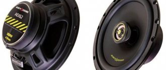
— JBL CS760C
ru.jbl.com/CS760C.html 6-1/2″, 50W RMS/150W max., 55 Hz–20 kHz, 4 ohm, 92 dB (2.83 V at 1 m) These speakers are now in my car doors.
One of them broke sometime (internal coil breakage) and I bought another set to replace it. If the magnetic system is removed from such a faulty speaker, a passive radiator (PI) can be made from it to increase the speaker's output in the low-frequency region. The removed magnet will also be used, as will be discussed below. — JVC CS-J420X
ru.jvc.com/mobile-entertainment/speakers/CS-J420X/ 4′, 21W RMS/210W max., 45 Hz–22 kHz, 4 ohm, 90 dB/mW These are budget branded car speakers purchased for experiments.
— 2 speakers 5W 8Ohm
, one of which is already installed in its acoustic design.
We will measure Thiel-Small parameters using the AudioTester program.
You can also use the Limp program from the Arta Software package, the cable in both cases is the same, and the measurement results of both programs should almost completely match - thanks to Vairon
and
yopopt
.
AudioTester produces repeatable results. I measured the same speaker on the main PC, secondary PC and laptop. All these measurements show very similar results. Also, the results of AudioTester measurements are recognized by Rospatent, for example, here is patent RU 2707905 (acoustic system with a slot-tuned Helmholtz resonator).
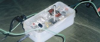
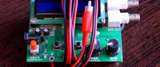
For measurements using AudioTester, you need to make a simple cable with one resistor. We prepare 2 pieces of shielded cable (i.e. a cable consisting of 2 separate multi-core wires with a common copper braid, such as a headphone cable), 2 3.5mm jack connectors for connecting to a PC, a 10 ohm resistor, wires with crocodile clips and/or with auto terminals for connecting to speakers. To make such wires, it is better to use an acoustic cable of sufficient cross-section (I made them from a 2x1.5mm2 cable).
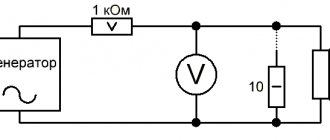
Cable diagram:
We solder such a cable, secure the wires with zip ties, then close this assembly with heat shrink. To avoid confusion, we put green heat shrink on the plug for connecting to the PC audio output:
Download the program from the official website www.audiotester.de/ and install it. On the computer, set the volume of the speakers and microphone to 100% and turn off all enhancements, if enabled (such as surround sound, loudness, etc.). We completely remove the microphone gain. Connect the cable to the computer. In the program, press the TSP button.
But before you measure the speakers, you need to do a calibration to take into account the resistance of the manufactured cable. Instead of a speaker, we connect a resistor with a resistance close to the speaker to the other end of the cable. I used a 6.6 ohm resistor for calibration. Click Start and look at the green curve to see how correctly AudioTester measures the resistance of the resistor. If necessary, change the value in the Impedance field until we get the most accurate match:
Now you can start measuring the speaker. As for how to do this correctly, there are 2 opposing points of view. Some argue that the speaker should be hung from a chandelier in the center of a large room with walls covered with carpets). Others argue that the speaker should, on the contrary, be clamped in a vice. In my opinion, it is correct to do as the author of AudioTester himself recommends - when measuring, the speaker should be placed on a soft pillow with the diffuser facing up.
The video below shows how to make settings based on the speaker you are measuring and follow the measurement procedure:
So, we measured the Thiel-Small parameters of our speaker. What to do with them next?
We save the results to a text file using the List / Print button and then enter these values into one of the cabinet calculation programs, for example JBL SpeakerShop, Bassbox Pro, UniBox, etc. There we select the desired type of housing for this speaker and the program itself calculates the dimensions of the selected housing.
We will launch the cabinet calculation program later, but now we will try to quickly analyze the obtained T/S parameters of our JBL CS760C speaker.
There are only three most important Thiel-Small parameters: Fs, Qts and Vas.
Fs
is the speaker’s own resonant frequency (without housing). The speaker reproduces frequencies below Fs poorly.
Qts
- this is the full quality factor of the speaker. The Qts value can determine the type of acoustic design most suitable for a speaker, as well as the speaker's tendency to drone at its resonant frequency (the higher the Q, the more booming it will be, under some conditions).
There are different classifications of the purpose of speakers depending on Qts, but still no consensus has been reached on this issue. For example, here is one such classification:
Qts > 1.2 - speakers for open drawers, optimally 2.4; 0.6 < Qts < 1.2 - speakers for closed boxes, optimally 0.7–0.8; 0.4 < Qts < 0.6 - speakers for bass reflexes, optimum - 0.4; 0.2 < Qts < 0.8 - speakers for systems with a passive radiator; Qts < 0.4 - speakers for horns.
Vas
is the equivalent volume, using it you can roughly estimate the minimum volume of the case for installing a speaker. For example, if Vas is equal to the volume of the body, then Fc and Qtc will increase by 1.4 times. And if the body volume is 3-5 times larger than Vas, this will practically not worsen the sound of the acoustics.
So, the JBL CS760C speaker has T/S parameters: Fs=75.5 Hz, Qts=1.02, Vas=10.37 l.
This car speaker is designed for installation in doors. The high quality factor of this speaker is quite appropriate, because... the internal volume of the door is not completely closed due to cracks and technological holes. Vas=10.37 liters means that if you put such a speaker in a closed box, its volume should be at least 30 liters (for example, a cube with dimensions 31x31x31cm), which is not a lot.
Are there ways to further reduce the size of the cabinet without noticeably changing the sound quality of the speakers?
Yes, I have. There are at least three of them:
— Acoustic Resistance Panel (ARP)
, allows you to reduce the quality factor of the speaker in the housing, the design of the PAS is selected experimentally;
— Packing the body with damping material
such as cotton wool or padding polyester with a density of up to 24 g per liter of volume, allows you to obtain a virtual increase in body volume up to 40%;
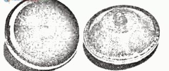
— Reverse magnet
, allows you to reduce the electrical quality factor of the speaker. Let's try to test its effectiveness in practice. Glue the magnet removed from the faulty speaker to the working speaker. Magnets should repel, not attract!
Let's measure a speaker with a return magnet attached:
We see that the quality factor of the JBL CS760C speaker has decreased from 1.02 to 0.84. How significantly this will reduce the volume of the case will be shown below.
In the meantime, let's continue our measurements.
Speaker JVC CS-J420X
T/S parameters: Fs=135.9 Hz, Qts=2.39, Vas=1.57 l.
Yeah…. Apart from a car, such a speaker can only be placed in an open box. Neither a reverse magnet nor a PAS will reduce the quality factor of 2.39 to an acceptable level.
Noname speaker SJ H9053201, 8Ohm 5W
T/S parameters: Fs=420.5 Hz, Qts=4.96, Vas=0.13 l.
This speaker was in the TV, the sound quality was not great)
Noname speaker 55085-010, 8Ohm 5W (in housing)
I measured this speaker just out of interest). It is also from a TV, has its own case, which I did not remove. The case is interesting in that it has a vibration-damping element in the shape of a cone, which redistributes sound waves into the rounded corners of the case:
This solution reduces vibrations and resonances of the housing. This speaker sounded much more pleasant, unlike its counterpart with the same power and impedance above. Even some low frequencies could be heard.
Calculation of the housing for the speaker based on the Thiel-Small parameters
Having the T/S parameters of the speaker of interest in hand, you can begin to calculate the housing for it. There are a lot of programs for calculating enclosures: JBL SpeakerShop, Bassbox Pro, UniBox, etc. These programs, as well as additional
Resistance or impedance of the driver
Although in everyday speech the words “resistance” and “impedance” are synonymous, when describing dynamic heads, the first term is usually attributed to the voice coil’s resistance to direct current, and the second is used to describe the dependence of its resistance to an alternating signal in the operating frequency range.
In physics, this division is also followed and “impedance” is defined as the complex resistance between two nodes of a circuit or two-terminal network for a harmonic signal, and resistance is the property of a conductor to impede the passage of electric current.
Thus, the resistance of a dynamic head is usually expressed as a numerical value in ohms, and a graphical form of representation is used to describe the impedance (where the vertical axis represents the resistance and the horizontal axis the frequency).
If you take measurements and plot an impedance graph for a real dynamic head, you can see that at its resonant frequency the resistance will be maximum. As a matter of fact, from this graph we can determine Fs.
This approach is incorporated into a large number of software products for measuring the parameters of dynamic heads and speaker systems. You will find an overview of them and download links in our PDF report “The best services and software for developing acoustics.”
Impedance curves are used when designing the acoustic design of dynamic drivers. DC resistance is usually indicated in the rating data (usually from 4 to 16 Ohms, but there are exceptions). I want to say right away that the resistance indicated in the passport is often inaccurate, and when calculating it should be double-checked, without relying on the manufacturer of the dynamic head.
Electrical quality factor of the speaker.
An interesting point is that when the speaker tries to return the diffuser to its original state, after removing the electrical signal, the speaker coil generates an EMF, moving in a magnetic field. The speakers, in turn, are directly connected to the amplifier via an audio cable.
The amplifier has almost zero resistance. And when the signal from the amplifier disappears, and the speaker is “on”, then it (the speaker) works as a generator. Moreover, it works as a generator, with maximum load (the coil outputs are practically short-circuited by the amplifier resistance). This load creates a fairly powerful braking force, forcing the coil and diffuser to stop quickly.
The average value of electrical quality factor (Qes) for a low-frequency speaker is from 0.2 to 0.9, but more often it is close to unity. And if we compare the parameters of the electrical quality factor with the values of the mechanical quality factor, we get the conclusion that vibration damping (energy loss) occurs mainly due to the electrical component.
Calibration:
First you need to calibrate the voltmeter. To do this, instead of a speaker, a 10 Ohm resistance is connected and by selecting the voltage supplied by the generator, it is necessary to achieve a voltage of 0.01 volts. If the resistor is of a different value, then the voltage should correspond to 1/1000 of the resistance value in Ohms. For example, for a 4 ohm calibration resistance, the voltage should be 0.004 volts.
Remember! After calibration, the generator output voltage cannot be adjusted until all measurements are completed.
High and low quality speakers.
A speaker has a high quality factor if the cone oscillations continue at the resonant frequency even when the signal is no longer supplied to the speaker, and the losses are very small. We'll talk about resonant frequencies another time.
But if the oscillations of the speaker fade out almost immediately after the signal to it disappears, and the speaker spends a lot of energy on various types of losses, then they say that such a speaker has a low quality factor .
In order not to hear the “re-reflection effect”, sounds like “hum” or “mumbling” in your speakers, and not to listen to the “finishing” of any sounds, when modifying the acoustics or making them yourself, you need to select speakers with a low quality factor.
Another way to put it is this: after the signal from the amplifier disappears, the speaker should immediately return to its place, which it usually occupies when no signal is supplied to it. This would be the ideal option, the ideal speaker. This way we will get from the speaker exactly the sound we want to hear.
Finding the inductance of the speaker coil L
To do this, you need the results of one of the readings from the very first test. You will need an impedance (impedance) of the voice coil at a frequency of about 1000 Hz. Since the reactive component (XL) is separated from the active Re by an angle of 900, we can use the Pythagorean theorem:
Rice. 6. Formula for coil impedance at a certain frequency
Since Z (coil impedance at a certain frequency) and Re (coil DC resistance) are known, the formula converts to:
Rice. 7. Formula for coil impedance at a certain frequency
Having found the reactance XL at frequency F, you can calculate the inductance itself using the formula:
Rice. 8. Coil inductance formula
Finding the diffuser surface area Sd
This is the so-called effective radiating surface of the diffuser. For the lowest frequencies (in the zone of piston action) it coincides with the design one and is equal to:
Rice. 5. Formula for calculating diffuser surface area
The radius R in this case will be half the distance from the middle of the width of the rubber suspension on one side to the middle of the rubber suspension on the opposite side. This is due to the fact that half the width of the rubber suspension is also a radiating surface. Please note that the unit of measurement for this area is square meters. Accordingly, the radius must be substituted into it in meters.