The wires and cables that are used when installing an audio system play an important role and must, at a minimum, ensure the transmission of power and signals with minimal losses. Power cable:
The main requirement for the cross-section of the power cable is a voltage drop of no more than 0.5 V over the entire length of the wire. The length is calculated taking into account the positive and negative wires. Based on these conditions, the cross-section of the power cable can be calculated using the formula:
Smin = 2•L• (Pnag / (Umin bat•Nbat)) •p/ΔU, (sq.mm),
where L is the distance from the battery to the consumer (m); R; — copper resistivity coefficient = 0.0175 (Ohm•sq.mm/m) at 20 C; ΔU - permissible voltage drop on the power cable = 0.2 V. (Allowed up to 0.5 V). Example. Load power 200 W/13.4 V at a distance of 4 m.
Smin = 2•4•(200 / (13.4• 1)) • 0.0175 / 0.2 = 10.4 (mm2).
Acoustic cable:
The acoustic cable is calculated using the following formula:
where D is the cable diameter, Pmax is the maximum power of the consumer, in this case the speaker (or the maximum power of the amplifier per channel). It is better to take a larger value for calculations in order to provide a margin for further growth. U is the network voltage, i.e. 12V. The formula is simplified.
Example for acoustics with a maximum power of 300 W:
(300/12)/10=2.5 mm. In total, you need a cable with a diameter of 2.5 mm.
Numerous recommendations and reviews from music lovers on choosing an acoustic cable provide advice and voice subjective opinions that have nothing to do with the real state of affairs.
According to the authors, who believe the advertising of cable manufacturers, the sound quality is significantly affected by the purity and structure of copper crystals, the external coating of the wires, the twist pitch and the number of cores, the insulation material and much more, which is not confirmed by mathematical calculations. Physics is an exact science and unfounded statements are not proof.
How to choose a section?
The wire cross-section is the most important indicator that you should pay primary attention to when choosing an acoustic cable.
If you visually imagine an acoustic cable in the form of a funnel, through which the power from the amplifier is transferred to the acoustic system, then the cross-section in such an imaginary exercise will act as the diameter of the hole in this funnel. Thus, if you select a cable that has an insufficient cross-sectional width, then the system will not the power necessary for full operation will be supplied. Such a drawback will be audible - the sound will not be dynamic, and the lack of necessary bass will also be obvious.
If you visually imagine an acoustic cable in the form of a funnel, through which power from the amplifier is transferred to the speaker system, then the cross-section in such an imaginary exercise will act as the diameter of the hole in this funnel. Thus, if you select a cable that has an insufficient cross-sectional width, the system will not receive the power necessary for full operation. Such a drawback will be audible - the sound will not be dynamic, and the lack of necessary bass will also be obvious.
In order to choose the correct cross-section, it is necessary to make the necessary calculations, which will be different for each individual cable. If we talk about the average permissible value, then for a medium-power speaker system of the floor-standing category a cross-section of 2.5 mm will be sufficient.
Brief information about wires
Connecting lines of fire protection systems must be made with fire-resistant cables with copper conductors with a round cross-section. For conductors with a cross section of less than 0.5 mm2, the diameter is indicated. To move from the cross-section (S, mm2) of the conductor to the diameter (d, mm) and vice versa, the following relationship is used: S = πd2 / 4, where S is the cross-section of the conductor, mm2, d is the diameter of the wire, mm, π is a constant 3.1415 .
The cross-section of the conductive wire for the case when the entire load (for example, loudspeakers) is connected directly to the source (power amplifier, switch), you can use the following relationship:
Substituting the load rate for copper D = 2A/mm2 into formula (1), we obtain a ratio widely used in practice:
Formula (2) is used for estimation and does not take into account the length and load distribution in the line.
What characteristics are most important for high-quality signal transmission?
From a technical point of view, a cable can be characterized by three physical quantities:
- Resistance.
- Inductance.
- Capacity.
Material and resistance. Impedance is perhaps the most important parameter for transmitting an audio signal. 99% of speaker cables are made from copper because... this metal has the lowest resistivity - 0.0175 μOhm*m. Only silver has less - 0.016 μOhm*m, however, the cost of an acoustic cable made of this metal is several times higher than the cost of copper. There is a concept of oxygen-free copper. This is pure copper, made in a special way - the percentage of impurities in such copper is much less than in ordinary copper, and the conductivity indicator is better - for the best grade M00, the resistivity is 0.01707 μOhm * m. This is the kind of copper that is used in the production of high-quality speaker cables.
The skin effect, also called the skin effect, about which much has been said, affects the level of resistance in the cable. This effect is due to the fact that the current passing through the conductor is distributed non-uniformly, the current density at the surface of the conductor is greater than at its center. The influence of the skin effect is most relevant for high frequencies, where the current density in the center of the conductor is extremely low, it is all distributed over the surface layer, and as a result, the cross-sectional area used decreases and the resistance increases. However, in the end, the impact of the skin effect on sound quality is unlikely to be noticeable to the average user.
There are cables with the combined use of several metals. For example, copper-plated aluminum - when aluminum is coated with a layer of copper, or a copper conductor is coated with silver. Whether such cables are better or not is a moot point; in most cases, this is only the manufacturer’s desire to increase its own profits, and not to improve quality.
Length of cable. A rule that is familiar to almost everyone is that the shorter the cable length, the better. As the length of the cable increases, the resistance of the cable increases, and the chances of interference and noise also increase.
In cases where a large cable length is required, or if there are a large number of sources of noise and interference nearby, the cable is shielded - layers of metal braiding are added to the dielectric braiding, which reduce the effect of external factors. This is often critical for audio systems in cars, as well as for applications in sound studios, where the length of the conductors can be 100 meters. In most cases, in domestic conditions, an unshielded speaker cable is sufficient.
Cable cross-section and number of cores. The speaker cable is manufactured mainly with a cross-section in the range of 2.5-4 square meters. mm, no less. This is the optimal cross section for transmitting an audio signal. The speaker cable is always made of stranded conductor. Unlike a conventional electrical cable, the thickness of the cross-section of the cores in an acoustic cable is smaller, and their number is greater.
Inductance and capacitance. In each cable, when an electrical signal passes through it, a magnetic field is created. With a large number of parallel conductors, the magnetic field can have a significant effect on the flowing signal. To reduce this influence, the conductors are twisted together in a certain way. Also, to reduce the influence of the magnetic field of each conductor, they are shielded by applying a layer of special varnish to each core.
Connectors. The most common source of poor quality is speaker cable connectors. This especially applies to products from the Chinese industry, in which the conductor inside the connector is not soldered to the terminal, but is clamped. Over time, the surface of the conductor and terminals oxidize, and crackling appears in the sound stream.
conclusions
- The measurements once again confirmed the theory. The results coincided with what I wrote in the previous article. This is not surprising.
- A regular cheap cable showed fairly good results. So good that there is no need to use anything more expensive.
- When engineers say that a cable does not affect the sound of the amplifier and speakers, what they mean is that a properly designed and selected cable changes the signal parameters (amplitude and phase) so slightly that it is absolutely imperceptible to the ear. And it's real. Of course, unless you believe in the magic that flows through the cable.
- And engineers also keep in mind that the cable should not affect the sound. How the color of your car should not affect its performance. And this is also real.
- A cheap cable has only one, but very big drawback - the cable is cheap. It is difficult for both the manufacturer and the seller to make a lot of money on such a cable. Therefore, they put a lot of effort into making people buy expensive cables. Moreover, in expensive cables, under the pretext of combating the skin effect, you can “accidentally” create a large inductance or capacitance. Then the influence of the inductance and/or capacitance of the cable will be noticeable to the ear, the cable will have a “own sound”, and it will be possible to force the consumer to repeatedly buy various expensive cables in search of the “best sound”.
- Therefore, there is a lot of information about how certain cables sound. And that the cable significantly affects the sound. And that the cable is the most important component of the audio system. It's natural that people want to make money by selling audio cables. Even if it means cheating a little.
- I'm not trying to fight this phenomenon. Those who want to be deceived will certainly allow themselves to be deceived. I appeal to those who trust reason.
05.05.2021
Total Page Visits: 1791 — Today Page Visits: 1
How to choose the cross-section of speaker cable for speakers
The main parameters when determining the cable cross-section for acoustics are the characteristics of the low-frequency path. Usually the nameplate power of the low-frequency amplifier and the speaker impedance are known. It is necessary to use not the rated power, but the maximum or peak power. First, the voltage in this circuit is determined. To do this, you need to multiply the peak power of the amplifier by the impedance of the acoustics and take the square root of the product. U=√P*R. For example, with a maximum ULF power of 60 watts and a speaker system resistance of 4 Ohms, the voltage in the cable will be about 15.4 volts.
Next you need to find out the current. To do this, the amplifier power is divided by the voltage: I=P:U or the resulting voltage is divided by the resistance.I=U/R. In both cases, the current in the circuit will be equal to 3.8 A. A wire with a cross-section of 1.5 mm2 can withstand a current of up to 15 amperes, therefore for these parameters such a cable will be quite sufficient. In household music systems, the connection length is short, so the wire’s own resistance can be neglected. The resistance of the wire between the amplifier and the speakers should be minimal, so it is recommended to use a larger cross-section of the wire, but it cannot be reduced.
Measurement results
The measurement results for all four cables are shown in Figure 9. Two parameters were measured:
- active (ohmic) resistance, on the graphs it is designated “R”.
- reactive (inductive) reactance, on the graphs it is designated “X”.
In fact, the measuring device shows the values of serial resistances Rs and Xs (Fig. 7). When measuring the active and inductive resistance of a cable, this is not important, but when it comes to measuring capacitance, I will tell you more about this.
Rice. 9.
Figure 9 itself is very interesting, but it is inconvenient to use due to the fact that all the cables had different wire cross-sections and different lengths: 10...12 meters. Therefore, next I show graphs of processed measurement results.
For greater clarity, I normalized the parameter graphs of each cable to the active resistance of this cable at a frequency of 100 Hz. That is, all further graphs show how the resistance of each cable changes in relation to its active resistance R at a frequency of 100 Hz. Then they can be compared correctly. In this case, the results are not affected by either the cable length or its cross-section. Design only.
And let's start, of course, with the most important thing - the terrible and terrible skin effect.
Physical characteristics of an audio cable that affect sound reproduction quality
Let's consider the degree to which the quality of an audio cable is influenced by the purity of the copper core, skin effect, braided shielding, roughness, core coating and insulation.
Effect of copper purity on the audio signal
According to GOST 859-2001, copper with a purity of more than 99% is used for the manufacture of cable wires, in which the maximum proportion of impurities in the worst case does not exceed 1%, which practically does not affect its conductivity.
| Table of purity of electrical grades of copper | ||||||||||
| Copper grade | M00 | M0 | M0b | M1 | M1r | M2 | M2r | M3 | M3r | M4 |
| Copper content,% | 99,99 | 99,95 | 99,97 | 99,00 | 99,00 | 99,70 | 99,70 | 99,50 | 99,50 | 99,00 |
The oxygen present in copper has a valve effect and works like a diode, rectifying a sine wave. In oxygen-free copper of grade M0, the amount of oxygen does not exceed 0.001%. In the deoxidized M1 grade it is 0.01%, which theoretically can add nonlinear distortions to the audio signal by no more than this amount.
In practice, the introduced distortion is many times less, since the diodes are shunted with pure copper. Thus, the presence of oxygen in copper does not affect the natural sound.
For reference. Scientists V. M. Bolshov and V. I. Gukin found that the human ear does not detect nonlinear distortions of less than 3%.
Influence of the skin effect
When alternating current passes through a conductor, an alternating electromagnetic field appears around it, which creates an electric induction field that interacts nonlinearly with the electromagnetic field. As a result, the current density from the center of the wire axis shifts to its surface. This behavior of alternating current is called the skin effect.
The skin effect begins to appear at frequencies above 100 Hz in wires with a cross-section of more than 0.75 mm2. Thus, low frequencies (bass) are not affected. As the frequency increases, a smooth manifestation of the skin effect begins, and at a frequency of 20 kHz, the loss increases to 0.25 dB, which is almost impossible to notice. But even if you have perfect hearing, you can always compensate for losses in the high-frequency range using an equalizer.
On wires with a cross section of less than 0.75 mm2, there is no skin effect in the audio range. Therefore, to obtain a cable without skin effect for connecting audio speakers to an amplifier, for example, with a cross-section of 1.5 mm2, it is enough to twist two insulated wires with a cross-section of 0.75 mm2. Many audio cable manufacturers do this.
About braided cable shielding
The non-ferrous metal shielding used in expensive audio cables does not protect against low-frequency electromagnetic fields, and high-frequency fields, from which shielding can protect, under normal conditions create an EMF in the cable wires of several microvolts.
The level of influence of such a field is hundredths of a dB, which is impossible to hear even when the signal is not sent to the speakers.
About the number of cores and their diameter in the wires of an acoustic cable
The number and cross-section of cores in the cable wires does not affect the sound quality. The more cores and the smaller their diameter, the more elastic the cable will be. The question is relevant if you need to frequently transport the audio system and twist the cable.
Effect of roughness and coating of cable wires
According to Ohm's Law, the current strength in a closed circuit depends only on its resistance, therefore even greater roughness of the wires will reduce the cross-section of the wire by 0.1%, which will have no practical effect.
Coating wires with noble metals is justified only to reduce the influence of the skin effect at frequencies above 100 kHz. Therefore, it does not matter for an audio cable. The insulating coating does a good job of protecting copper from external influences. It may be justified to cover only the terminals at the ends of the wires.
Influence of cable wire insulation material
Any electrical wires, including those for connecting sound speakers, are covered with insulation to protect against short circuits and external environmental influences. The insulation is made of dielectric material and does not take part in the passage of current through the cable. Since the voltage supplied from the amplifier to the speakers does not exceed hundreds of volts, the insulation material does not matter.
Conclusion
The quality of an acoustic cable is determined only by its cross-section.
The purity and structure of copper crystals, the outer coating of the wires, the twist pitch, the cross-section of cores in the wire and their number, the insulation material - have virtually no effect on the natural reproduction of musical works.
If the cross-section of the wires is insufficient, part of the power will be dissipated on them and at moments of maximum volume, low frequencies (bass) will sound without distortion, but somewhat quieter, because they account for more than 70% of the total sound power.
Exploitation
In conclusion, we will give some recommendations regarding the use of speaker cable. Since it is a rather delicate structure, it is necessary to adhere to certain rules, which will significantly extend its service life:
- It is unacceptable to twist, break or bend the cable, especially for single-core models;
- the audio wire must not be crushed, compressed, or subjected to other mechanical influences;
- It is not recommended to place speaker cables in parallel with network cables, as this can cause interference and, as a result, loss of sound quality;
- do not lay the cable near structures that use ferromagnetic materials;
- the ends of the wire cannot be left “open”;
- it is unacceptable to connect positive and negative wires to each other, since this can lead to a short circuit and, as a result, damage to the amplifier;
- It is better to disconnect the cable that is not in use;
- Do not extend the wire, this will lead to persistent interference;
- During operation, the contacts may undergo oxidation, so they must be cleaned from time to time;
- If possible, try not to use long cables unless necessary.
Calculation of the cross-section of an acoustic cable for connecting a speaker
According to the recommendations, the resistance of the wire for connecting the speaker should not exceed 5% of its resistance. The table shows the maximum permissible resistance of the cable wires depending on the resistance value of the speaker.
| Permissible cable resistance for connecting a speaker | |
| Speaker resistance, Ohm | Conductor resistance, Ohm |
| 1,0 | 0,05 |
| 2,0 | 0,1 |
| 4,0 | 0,2 |
| 8,0 | 0,4 |
| 16,0 | 0,8 |
When calculating, it should be taken into account that the total resistance of the cable will be twice as large, since it consists of two conductors. The lower the cable resistance, the better.
A meter of copper wire of any cross-section has a known resistance. Therefore, knowing the permissible cable resistance and its length according to the table, you can choose the appropriate one.
| Resistance of a copper speaker cable depending on its length | |||||||||||
| Diameter mm | Section mm2 | Resistance, meter×Ohm | |||||||||
| 1 | 2 | 3 | 4 | 5 | 6 | 7 | 8 | 9 | 10 | ||
| 0,25 | 0,05 | 0,35 | 0,70 | 1,05 | 1,40 | 1,75 | 2,10 | 2,45 | 2,80 | 3,15 | 3,50 |
| 0,50 | 0,20 | 0,09 | 0,18 | 0,26 | 0,35 | 0,44 | 0,53 | 0,62 | 0,70 | 0,79 | 0,88 |
| 0,80 | 0,50 | 0,04 | 0,08 | 0,12 | 0,16 | 0,20 | 0,23 | 0,27 | 0,31 | 0,35 | 0,39 |
| 1,0 | 0,79 | 0,022 | 0,04 | 0,07 | 0,09 | 0,11 | 0,13 | 0,15 | 0,18 | 0,20 | 0,22 |
| 1,5 | 1,77 | 0,01 | 0,02 | 0,03 | 0,04 | 0,05 | 0,06 | 0,07 | 0,08 | 0,09 | 0,10 |
| 2,0 | 3,14 | 0,0055 | 0,011 | 0,017 | 0,022 | 0,027 | 0,033 | 0,038 | 0,044 | 0,049 | 0,055 |
| 2,5 | 4,91 | 0,0035 | 0,007 | 0,011 | 0,014 | 0,018 | 0,021 | 0,025 | 0,028 | 0,032 | 0,035 |
| 3,0 | 7,07 | 0,0007 | 0,0014 | 0,0021 | 0,0028 | 0,0035 | 0,0042 | 0,0049 | 0,0056 | 0,0063 | 0,0077 |
For example, you need to choose a cable 2 meters long to connect a speaker with a resistance of 4 Ohms. From the table “Permissible cable resistance for connecting an audio speaker” we determine that the resistance of the cable wires should not exceed 0.2 Ohm. The cable has two wires, which means that the value must be divided by two, it turns out to be 0.1 Ohm. In the 2 meter column, the appropriate value is 0.08 Ohm; moving our gaze horizontally to the left we see that a cable with a wire cross-section of 0.5 mm2 (diameter 0.8 mm) is suitable.
As you can see, using the above tables, choosing the wire cross-section for the speaker is inconvenient. Therefore, both tables have been combined into one, which will allow you to quickly and accurately select a cable.
| Table for selecting the cross-section of the speaker cable depending on the impedance of the speaker | |||||||||||||||
| Speaker resistance, Ohm | Wire cross-section (mm2) depending on cable length (m) | ||||||||||||||
| 1 | 2 | 3 | 4 | 5 | 6 | 7 | 8 | 9 | 10 | 11 | 12 | 13 | 14 | 15 | |
| 1 | 0,68 | 1,36 | 2,04 | 2,72 | 3,40 | 4,08 | 4,76 | 5,44 | 6,12 | 6,8 | 7,5 | 8,2 | 8,8 | 9,5 | 10,2 |
| 2 | 0,35 | 0,70 | 1,05 | 1,40 | 1,75 | 2,10 | 2,45 | 2,80 | 3,15 | 3,35 | 3,85 | 4,2 | 4,5 | 4,9 | 5,2 |
| 4 | 0,18 | 0,36 | 0,54 | 0,72 | 0,90 | 1,08 | 1,26 | 1,44 | 1,62 | 1,8 | 2,0 | 2,2 | 2,3 | 2,5 | 2,7 |
| 8 | 0,09 | 0,18 | 0,27 | 0,36 | 0,45 | 0,54 | 0,63 | 0,72 | 0,8 | 0,9 | 1,0 | 1,1 | 1,2 | 1,3 | 1,4 |
| 16 | 0,04 | 0,08 | 0,12 | 0,16 | 0,20 | 0,24 | 0,28 | 0,32 | 0,36 | 0,40 | 0,44 | 0,48 | 0,52 | 0,56 | 0,60 |
Now it is enough to find out the required wire cross-section in the cable length column by the speaker resistance. For example, to connect a speaker with a resistance of 4 Ohms, located 3 meters away from the amplifier, you will need a cable with a wire cross-section of 0.54 mm2.
GOST 22483-2012 prescribes a standard range of cable wire cross-sections for manufacturers, and a wire of the selected cross-section may not be available for sale.
| Table of standard cross-sections of electrical wires according to GOST 22483-2012 (IEC 60228:2004) | |||||||||||||
| Standard cross-section of wire cores, mm2 | 0,12 | 0,20 | 0,35 | 0,50 | 0,75 | 1,0 | 1,5 | 2,5 | 4,0 | 6,0 | 10 | 16 | 25 |
| Diameter, mm | 0,39 | 0,50 | 0,35 | 0,67 | 0,98 | 1,13 | 1,38 | 1,78 | 2,26 | 2,76 | 3,57 | 4,51 | 5,64 |
Therefore, I decided to make a table with the help of which the choice of wire cross-section for an acoustic cable can be made taking into account the standard range of sections.
| Selection table for standard speaker cable cross-section | |||||||||||||||
| Speaker resistance, Ohm | Standard wire cross-section (mm2) depending on cable length (m) | ||||||||||||||
| 1 | 2 | 3 | 4 | 5 | 6 | 7 | 8 | 9 | 10 | 11 | 12 | 13 | 14 | 15 | |
| 1 | 0,75 | 1,5 | 2,5 | 4,0 | 4,0 | 4,0 | 6,0 | 6,0 | 6,0 | 10 | 10 | 10 | 10 | 10 | 10 |
| 2 | 0,35 | 0,75 | 1,0 | 1,5 | 2,5 | 2,5 | 2,5 | 4,0 | 4,0 | 4,0 | 4,0 | 6,0 | 6,0 | 6,0 | 6,0 |
| 4 | 0,2 | 0,5 | 0,5 | 0,75 | 1,0 | 1,0 | 1,5 | 1,5 | 2,5 | 2,5 | 2,5 | 2,5 | 2,5 | 2,5 | 4,0 |
| 8 | 0,12 | 0,2 | 0,35 | 0,35 | 0,5 | 0,75 | 0,75 | 0,75 | 1,0 | 1,0 | 1,0 | 1,5 | 1,5 | 1,5 | 1,5 |
| 16 | 0,12 | 0,12 | 0,12 | 0,2 | 0,20 | 0,35 | 0,35 | 0,35 | 0,5 | 0,5 | 0,5 | 0,5 | 0,75 | 0,75 | 1,0 |
The wire cross-section is selected using this table, the same way as using the previous one, only as a result you will immediately receive a standard value.
If you have pieces of copper cable of sufficient length, you can find out whether it is suitable for use as an acoustic cable.
It is impossible to measure the wire cross-section with instruments, but it can be calculated from the diameter measured with a caliper or micrometer.
| Online calculator for calculating wire cross-section by diameter |
| Enter wire diameter, mm: |
Any stranded copper wire for electrical wiring will work for the speaker cable. If the cross-section of the multi-core cable wire is unknown, then it can be determined using the method published on the website.
Introduction
Warning systems are widely used in various fields of human activity, for example, warning and evacuation control systems, emergency warning systems (local LSO and centralized central warning systems). The main purpose of the warning system is to notify people about a particular threat, to convey to them information concerning their personal safety in the event of any emergency situations: fires, man-made disasters, terrorist threats. Warning systems are a mandatory component of almost any security system, in which they are the final executive element - an intermediary between technical means and people. The reliability of information transmission in the warning system is confirmed by electroacoustic calculations, part of which is the calculation of the optimal cross-section of the conductor of the wire, minimizing losses
.
Alarm systems, depending on the conditions of use and the method of transmission, can be divided into wireless and wired. Wired systems that transmit sound or speech information are called broadcast systems.
Broadcasting systems, depending on the principle of construction, can be divided into local and distributed. Distributed audio broadcast systems use the principle of transformer matching, in which specialized transformer loudspeakers are connected to broadcast amplifiers - amplifiers with a transformer output stage. When building distributed systems, loudspeakers, which are the load, are connected to the connecting line in parallel and distributed along it. With transformer matching, sound information is transmitted at increased voltage, which reduces currents and, consequently, the load on the wires, increases the length of the connecting line and the signal transmission range. Extended transmission lines are built as follows: first, the main line is laid, to which the load is connected through distribution boxes.
In transmission lines, losses inevitably occur due to the presence of the conductor's own resistance. Large losses can lead to a decrease in the level and quality of the transmitted signal, so the task of calculating losses on wires and the associated task of calculating the optimal cross-section of the conductor of a connecting line wire is not unimportant.
What cables to connect
To connect speakers to a TV, many cables are used, depending on the type of connection and the available outputs on both devices. The most commonly used wires are 2RCA - 2RCA, mini Jack - mini Jack, SCARD - SCARD or combinations based on them, less often - coaxial or optical.
If your connected devices have HDMI outputs, we recommend using them because they will provide the best sound quality. However, regardless of the connection type, you need to purchase a high-quality cable. Cheap Chinese wire is characterized by significant signal losses during transmission, which means poor sound quality. In the worst case, such wires will not work at all.
Signal flow
The first thing to know about audio transmission is that sound is linear. This usually requires an exit or an entry. Audio signal receivers are connected to the ports of the first type, and its sources are connected to the second type. In this case, the outputs are connected to the inputs through a chain of devices.
For example, when connecting a CDJ or controller to a DJ mixer, the outputs of the first device must route audio to the inputs of the second. In this case, the MASTER, BOOTH and REC OUT ports are outputs, and the channels are inputs.
What is twisted pair
When choosing a cable, you will come across the term twisted pair. These are pairs of twisted and insulated conductors. Using two insulated cords at once reduces magnetic interference and provides additional protection from mechanical or chemical damage. These cords are commercially labeled TP: Twisted Pair.
Twisted pair is used in acoustics when the length of the conductors must be significant. But be careful: there are 7 categories of these cords. Choose category 6 or 7 conductors because they are made only from copper, while other pairs can be made from copper-plated aluminum or steel. Pure copper increases the cost of acoustics, but it pays off in purity of sound.
Cables of this type can be single-core or multi-core. This affects the sound: the farther the conductors are spaced from each other, the less coherent the sound.
Multicore twisted pair cable category 6
Audio cable measurements
An example of a measurement result is shown in Figure 7. In principle, you can use such results, they are quite good. But for greater convenience, I exported the measurement results to Excel and built more convenient and visual graphs there.
Rice. 7.
Measurements were carried out in the range from 100 Hz to 100 kHz. It makes no sense to use lower and higher frequencies. The step along the frequency axis was equal to 1/6 octave, which provided excellent frequency resolution. Figure 8 shows an example of a graph generated from the measurement results. The graph shows the points at which measurements were made - there are sixty of them. In other graphs, such points are not shown for greater clarity of the graphs.
Rice. 8.
Comparison of acoustic wire and electric
Appearance and rigidity
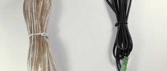
And so, let's continue studying and comparing. Let's strip the insulation and look at the copper conductors themselves.
This wire is acoustic, the manufacturer's name is OEHLBACH
The other wire is electrical, the manufacturer can be any, but its appearance will be the same.
Purely visually - they immediately have differences
The first sample was very soft to the touch and bending, which caused me some caution and suspicion - “will it really be able to withstand the loads declared by the manufacturer?” Hope so. The second wire is three times stiffer in bending
What causes this? Looking at the wires, you can immediately notice that each wire of the second wire (electric) is much thicker than that of the audio wire (acoustic). This is the reason for such a “softness” to the touch.
The second thing that makes the acoustic wire flexible is the absence of a second protective sheath. In an electrical wire, each core has its own insulating sheath. The wires are covered on top with a common (usually white) sheath. It is quite thick and made of PVC.
The speaker wires are covered with a silicone-based material (transparent), soft to the touch. And the absence of a second insulating shell makes it possible to obtain a “soft” wire for acoustics.
Line loss calculation
Extended lines have a fairly large intrinsic resistance, which leads to dissipation (loss) of part of the power on them. This fact cannot be ignored. In practice, voltage losses are initially calculated, and then they move on to power losses.
Voltage loss - the ratio of the voltage on the line Uл to the total voltage at the input of the line Uin:
According to Kirchhoff’s law, the ratio of resistances is proportional to the ratio of the voltages incident on them, therefore it is more convenient to express the voltage losses Pn through the previously obtained line resistance Rl and load resistance Rl:
Let's determine the amount of voltage loss for a distributed line. Since the distribution coefficient Kp (Table 2) demonstrates a decrease in the length of the line, and, consequently, its resistance Rl, the losses in such a line should decrease accordingly.
Let's supplement formula (15) with the distribution coefficient Kp, Table (2):
In practice, not only voltage losses are calculated, but also power losses.
Power losses are the ratio of the power allocated on the line Pl to the total applied power: the sum of the powers allocated on the line and on the load Pn.
It is convenient to calculate power losses through voltage losses (16), for which it is enough to take into account that the load power is directly proportional to the square of the load voltage (see formula 6):
Example: From (18) it is clear that with voltage losses of more than 25% (the value of 25% according to existing standards is the maximum permissible), power losses (Pm = (1–((100–25)/100)2)* 100 = 44%) are approaching 50% (the power decreases by 2 times (a decrease in power by 2 times (corresponds to a decrease in sound pressure by 3 dB), which is noticeable to the listener)), therefore, we will consider the magnitude of voltage losses Pn > 25% to be critical.
Criterias of choice
Selecting an acoustic cable for speakers is an important and responsible task that should be approached with the utmost seriousness and responsibility. It is best to rely on technical factors. Let's look at some of them:
- when purchasing a cable to connect speakers together, you should not automatically assume that you will purchase a high-quality product; be prepared even for a negative outcome;
- give preference to products manufactured by proven, popular and reputable companies among users - such products will meet all international standards;
- when choosing a cable cross-section, it is best to choose one of sufficient width - this is necessary so that a sufficient amount of current can pass through it;
- if you are in doubt about which cable to take, then give preference to the option that is coated with varnish on top (the whole point is that such a coating will help protect you from short circuits);
- When checking the cable's performance, you should make sure that the sound quality does not deteriorate over time;
- As for resistance indicators, they must have values that exceed the arithmetic average (remember that resistance affects the level of signal transmission quality), etc.
Adapters
Sometimes it happens that different audio equipment that requires connection is equipped with different types of connectors (for example, when you need to connect a two-channel DDJ-SR controller, which has only 1/4″ outputs, to two speakers with XLR inputs). The easiest way to solve this problem is to use special adapters. Although they are convenient, it is better to use special speaker cables (these can also be considered adapters with a wire between the connectors).
Adapters can be bulky and, in the case of some manufacturers, not the most reliable devices, capable of reducing signal levels and introducing noise. Given that most speaker equipment tends to be connected horizontally, the heavy weight of the adapter can overload the sockets and lead to equipment failure.
Thickness matters!
So what thickness should you choose for connecting acoustics? If we don’t ask ourselves about the quality of copper, then let’s take into consideration only the length and cross-section. In what follows I will say “acoustic wire,” but mean a simple wire (electrical). For many music lovers, and even more so audiophiles, this is a very important point. But let's not discuss brands even of electrical wires. We have already touched on this topic.
Speaker wire length
Each speaker will have its own wire, its own length, since everyone has different rooms where they are supposed to listen to music. And the length should be selected so that the wire is exactly enough for connection, or at a convenient place for laying it, so that you don’t trip over the wire later, so that it would be convenient to clean the room.
But remember that the longer the wire, the thicker it should be. Purely from school physics, so that “more electrons rush through the wire per unit of time.” The larger the size of the acoustics, I assume, the more powerful the speakers will be and they will require a lot of energy. Only then will the speakers be able to deliver their full potential.
Let’s imagine that the speakers (let’s assume their height is 1.2 meters) stand three meters from each other, and in the middle there is equipment that will “rock” the acoustics. Then, for connection you will need 2-2.5 meters of wire for each speaker. We leave approximately half a meter for connection to the terminals, since they are often located higher than 30 centimeters from the floor. And another half meter for connecting to the amplifier terminals.
But this is all approximately! This is approximately what it will turn out to be, well, maybe even a little less. But it is clear that making a coil of wire under the equipment rack from “extra” wire is absolutely not worth it.
Speaker wire thickness
Now about the reason why this article was started – about thickness.
Let's make it simpler. Study the table below. Let's limit ourselves to a table of up to 10 meters. Further numbers will be approximately the same as when using a wire 10 meters long. But I don’t think that anyone at home intends to use a wire even 10 meters long.
| Wire cross-section (mm 2 ) | ||||||||||
| Speaker resistance, Ohm | wire length (meters) | |||||||||
| 1 | 2 | 3 | 4 | 5 | 6 | 7 | 8 | 9 | 10 | |
| 1 | 0,75 | 1,5 | 2,5 | 4,0 | 4,0 | 4,0 | 6,0 | 6,0 | 6,0 | 10 |
| 2 | 0,35 | 0,75 | 1,0 | 1,5 | 2,5 | 2,5 | 2,5 | 4,0 | 4,0 | 4,0 |
| 4 | 0,2 | 0,5 | 0,5 | 0,75 | 1,0 | 1,0 | 1,5 | 1,5 | 2,5 | 2,5 |
| 8 | 0,12 | 0,2 | 0,35 | 0,35 | 0,5 | 0,75 | 0,75 | 0,75 | 1,0 | 1,0 |
| 16 | 0,12 | 0,12 | 0,12 | 0,2 | 0,2 | 0,35 | 0,35 | 0,35 | 0,5 | 0,5 |
We compare the values indicated in the columns and look at the table. For example, my speakers indicate 8 ohms. I look at the left column, looking for my line. I look at the corresponding column - the length of the wire. My length is 4 meters. And at the intersection of the row (4 Ohms) and the column (4 meters) - the cross-section of the wire that I need is obtained - 0.35 mm 2. But somehow these numbers confuse me...
In fact, now I have my acoustics connected using PVA wire 2*1.5 mm2, in round PVC insulation, with stranded copper wires. They fit well with the terminal connectors. You will say that he is tough and too fat! But this is relative. All you have to do is lay the wire once, untwist it so that it doesn’t get pulled into rings, and it will stay like that for at least a hundred years. Rigidity does not play a special role here and does not interfere in any way.
Calculation of the resistance of the conductor of a wire depending on the length and temperature
To determine the resistance of a wire strand, we use the well-known relationship: the resistance of a wire strand is directly proportional to the length and inversely proportional to the cross-section of the wire strand
:
Most references give the value of the resistivity of the current-carrying wire core for copper r = 0.0175 Ohm*mm2/m. This value corresponds to temperature t=0°С. With increasing temperature, the resistivity of the wire core increases noticeably, which cannot be ignored in calculations.
Dependence of the resistivity of the wire core on temperature:
ATTENTION: Formulas (3) and (4) can only be used if the characteristics of the cable used are missing.
Example: for a fire-resistant cable UTP-3ng(A)-FRLS Nx2x0.52, the manufacturer’s website provides the following characteristics (see Fig. 1):
Rice. 1 — Electrical parameters of fire-resistant cable UTP-3ng(A)-FRLS Nx2x0.52
Characteristics of speaker wires
The excellent sound resulting from the transmission depends on the following factors:
- Material type.
- Insulation characteristics.
- Internal diagram of the structure of the material.
For example, the purity and depth of bass is absolutely dependent on the metal used. Other parameters affect the timbre and cohesion of the resulting sound. As mentioned above, only copper is the best metal for such wires. But it also comes in different quality.
Copper cables are divided into several categories:
- TPC is coarse copper, used in wires in the budget price segment. Used for low sound requirements.
- OFC is oxygen-free and has excellent conductivity. This conductor is available only in the average budget product category, as it transmits the signal without the slightest loss or interference. Reasonable price and decent quality have made this product popular all over the world.
- RSOSS is pure copper obtained by the principle of melt extraction without interruption. The technology was created in China. Products containing such copper occupy a leading position and are positioned as expensive goods.
Unlike copper, precious metals conduct current better. But in terms of price, silver is much more often used for the production of wires. For example, the best speaker cable with embedded silver can cost from 100 euros. Such expensive wires are mainly used for elite or concert equipment. Composite wires are also considered promising. In addition, there are also component ones, where carbon is added along with copper, which creates additional protection against distortion and other positive properties.
Calculation algorithms
Algori
- Let's calculate the loss coefficient, formula (19).
- Let's calculate the distribution coefficient, Table (2).
- Let's calculate the resistivity of copper, taking into account temperature, formula (4).
- Let's calculate the total load in the line, formula (8).
- Let us substitute the obtained values into formula (20).
Algorithm No. 1 “Calculation of voltage losses in an existing line
- Let's calculate the resistance of the wire core, taking into account the temperature, formulas (4), (5).
- Let's calculate the total load in the line, formula (8).
- Let's calculate the load resistance, formula (6).
- Let's calculate the distribution coefficient, Table (2).
- Let's calculate the voltage losses, formula (16).
What is a bottleneck
The “bottleneck” metaphor, which has taken root in the terminology of the computer industry and electronics, management, psychology and other areas of human knowledge and activity, denotes an element that slows down the entire system, regardless of the quality of its components.
A speaker cable can also become a bottleneck: an incorrectly selected or low-quality cable reduces system performance and distorts the sound, since it is not able to correctly transmit frequencies emanating from the amplifier.
So, what characteristics of a conductor should you consider when choosing?
Cable production
Here the range of manufacturers is much wider than in the case of connectors. In addition, as practice shows, there is a point here that not all types or brands of cables are equally good. That is, along with excellent cables, the manufacturer’s line can have either an excellent or a rather mediocre cable. The most famous manufacturers of cable products are the Japanese Canare, the German Klotz, Sommer Cable and Cordial. A lot of good things have been heard about the Belden company, founded back in 1902 by Joseph Belden in Chicago, USA. They say that all the commutation of one of the largest rolling mills in the world is carried out using Belden products.
Which speaker cable is better?
According to their design, wires for sound systems can be single-core or multi-core. They use polyvinyl chloride, polyethylene or Teflon as insulation. Wires can be single or double, round or flat. To avoid a large number of connecting lines for speaker systems, a double cord is usually used, where two insulated parallel conductors are placed in a common plastic sleeve. To increase noise immunity, some types of connecting lines have a metal shield in their design.
To give the wire additional rigidity, a protective mesh made of elastic plastic or composite may be placed on top of the plastic insulation. At the ends, closer to the connection points, the line is divided into two separate conductors. To connect the wires to the amplifier and output systems, the wires are equipped with end connectors. The quality of transmission of audio frequency signals is affected by the design of conductive lines. Most often, a multicore structure is used as connecting lines, where the conductor consists of a large number of thin wires. Single-core wires are used extremely rarely. The stranded conductor can have the following configuration:
- Beam-shaped
- Concentric
- Rope
In the first case, the cores are arranged in an arbitrary bundle. This type of speaker cable for speakers has low performance and is almost never used for connection. In the second case, the veins form a package of a regular round shape. The parameters of this line meet all standards of high-quality sound. In a rope configuration, individual cores form twisted pairs, which promotes good signal transmission. The output low-frequency wire may have a flat cross-section rather than a round one. In it, each line consists of several insulated conductors arranged in parallel.
Male and female connector types
Informally, pin connections that have a protruding part are called “male” connections, and female contacts are called “female” connections.
Most wires used to connect audio equipment have male-type connectors on both sides, with female-type ports installed on the equipment. XLR cables (discussed in more detail below) have a male connector on one side and a female connector on the other. In this case, the outputs on the equipment always have pin contacts, and the inputs always have socket contacts.