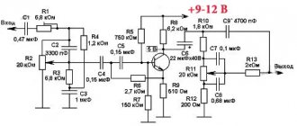
To obtain a full-fledged low-frequency power amplifier, a good power source is required; a diagram of a simple power supply for an UMZCH is shown. The sound quality depends almost as much on the parameters of the power source as on the amplifier itself, and you should not be negligent in its manufacture.
There are more than enough descriptions of calculation methods for standard transformers. Therefore, here we offer a description of a switching power supply that can be used both with amplifiers based on the TDA7293 (TDA7294), and with any other AF power amplifier, both on microcircuits and on transistors.
The basis of this power supply unit (PSU) is a half-bridge driver with an internal oscillator IR2153 (IR2155), designed to control MOSFET and IGBT technology transistors in switching power supplies.
↑ Not all cases are equally useful
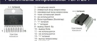
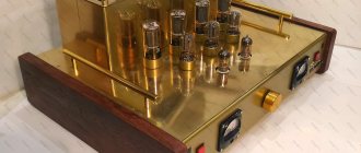
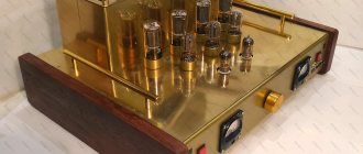
So, let's begin! I made two amplifiers on everyone’s favorite TDA7294 microcircuit according to the AudioKillera scheme and made a very inconvenient metal case for them and covered them with self-adhesive wood-like material - it didn’t turn out very well. It was difficult to climb inside, and besides, the power supply was built on a TS-180 transformer plus 25000uF*50V capacitors. But one day, while sorting out the trash in my room, I came across this miracle
This is a resistance magazine, a black Bakelite box with 6 biscuit switches. I live in a dormitory, a student at the Taganrog Technological Institute (Radik) SFU. Apparently the previous owners of the room stole this box, found it in some metrology laboratory, and forgot it here... The top cover with the switches is gone and I have an almost finished amplifier case in my hands! The only problem is how to fit the TC180 into such a box, and it was difficult with the radiators...
What if you use an impulse gun? The IIP will fit in there without any problems. I decided to place it at the bottom of the box, and place the amplifiers with the radiators outward, that is, up.
Schematic diagram
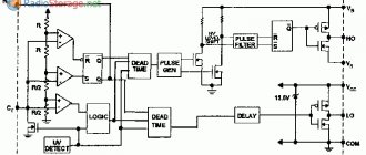
The functional diagram of the microcircuits is shown in Figure 1, the dependence of the output frequency on the ratings of the RC master chain is shown in Figure 2.
The microcircuit provides a pause between the pulses of the “upper” and “lower” switches for 10% of the pulse duration, which makes it possible not to worry about “through” currents in the power part of the converter.
Rice. 1. Functional diagram of microcircuits IR2153, IR2155.
The practical implementation of the power supply is shown in Figure 3. Using this circuit, you can make a power supply with a power from 100 to 500 W, you only need to proportionally increase the capacitance of the primary power filter capacitor C2 and use the corresponding power transformer TV2.
Rice. 2. Graphs of the dependence of the output frequency on the ratings of the RC-drive chain for the IR2153 microcircuit.
The capacitance of capacitor C2 is selected at the rate of 1... 1.5 µF per 1 W of output power, for example, when manufacturing a 150 W power supply, a capacitor of 150... 220 µF should be used.
Rice. 3. Schematic diagram of a switching mains power supply for 100-500W low-frequency amplifiers.
The VD primary power supply diode bridge can be used in accordance with the installed primary power supply filter capacitor; with capacitances up to 330 µF, 4...6A diode bridges can be used, for example RS407 or RS607.
With a capacitor capacity of 470... 680 µF, more powerful diode bridges are needed, for example RS807, RS1007.
↑ Impulsnik
My ordeals with IIP are described in detail in this forum thread //forum.datagor.ru/index.php?showtopic=5627&st=42 Here it is:
Fragment excluded. The full version is available to patrons and full members of the community.
IR2153 is powered from the midpoint of the divider, controls the field workers, and they supply pulses with a frequency of several tens of kilohertz to the primary. The scheme worked immediately (“Well, yes, right away!” someone who read that forum thread might say, but it turned out that everything was correct, my crooked hands are to blame).
Trans was calculated on the advice of the author of the diagram in the Transformer-2 program. Everything was exactly as planned - at idle, and when I connected the amplifiers the voltage dropped. Then a series of experiments followed, with frequency-setting elements C9 and P1 and the secondary of the transformer, as a result, nirvana was achieved at ± 30V output voltage.
Transformer
- 3 glued rings
Fragment excluded. The full version is available to patrons and full members of the community.
As I understand it, the master elements need to select the correct frequency, so that the core does not go into saturation, and so that the field workers do not go into self-heating. By the way, I didn’t have an oscilloscope, but if you have one, it simplifies everything a little. Half of the parts for the SMPS came from the old power supply for the computer, and the radiator came from there.
The real problem was to get a half-bridge with a common anode; I couldn’t find it anywhere, so without further ado I created pornography from 2 Schottky diodes in TO-220 cases. The space on the printed circuit board for stabilizers for the amplifier service circuits was not used.
Before turning on this, or any SMPS, you need to check everything, and check it again, the first turn on is through a 100-150W incandescent lamp, if something goes wrong it will signal, and the field workers may not “go to conquer low-Earth orbit” ©AlexD. The use of SMPS did not affect the sound, but the entire amplifier began to weigh less than one TC180.
Switching power supply for TDA7294 on IR2153
Somehow I had the urge to assemble an amplifier based on the TDA7294. Moreover, it was necessary to collect it as soon as possible. My birthday was just around the corner, and it was planned to celebrate it outdoors, to the sounds emitted by my rare Radiotekhnika S30 speakers.
The amplifier was assembled immediately. For those interested, read the article “Woof amplifier on TDA7294“. It's time to assemble a switching power supply. The small dimensions of the source were extremely important.
The simplest switching power supply circuit based on ir2153 was chosen.
The Internet is full of similar schemes slightly different from each other. Not all of the diagrams are working, as they are on the network. I didn’t understand this right away either, so I suffered a little. The diagram I have given is completely working. By observing all the ratings of this circuit and using my printed circuit board, you will save time on correcting your own and others’ mistakes.
A more complex analogue of this circuit is described in the article “Switching power supply for a low-frequency amplifier on the ir2153 with a power of 300W.” This circuit is distinguished by the presence of an overload protection unit and a smooth start.
The simplicity of the SMPS circuit for TDA7294 on ir2153 allows beginners to easily repeat it. Another plus is the dimensions. The switching power supply board measures 80mm wide and 80mm high.
The principle of operation of the circuit. How the power supply on the ir2153 works is described in the article “Switching power supply for a low-frequency amplifier on the ir2153 with a power of 300W.”
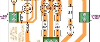
The varistor is not shown on the circuit diagram, but it is on the printed circuit board. In principle, you don’t need to install it, since it plays almost no role; it serves as protection against power surges in the network (no jumpers need to be soldered in, we just don’t install a varistor and that’s it).
The NTC thermistor, when turned on for the first time, limits the current surge; when charging the mains and output electrolytes, after a while it heats up and its resistance decreases. Simple, but not entirely reliable protection. When turned on again, when the thermistor is heated, the protection is no longer effective. But as practice has shown, the power supply is reliable and does not fail, as some people write in the comments.
Timing elements R2 and C3 are selected in such a way that the driver provides generation of pulses with a frequency of about 70 kHz. The program for calculating R2 and C3 is located under the article, you can calculate it for the frequency you need.
Elements.
| DESIGNATION | TYPE | RATING | QUANTITY | A COMMENT |
| Power Driver | IR2153 | 1 | ||
| VT1,VT2 | MOSFET - transistor | IRF740 | 2 | |
| VDS1 | Diode bridge | RS607 | 1 | 6A 1000V |
| VDR1 | Varistor | MYG14-431 | 1 | You don't have to put it |
| NTC | Thermistor | 5D-9 | 1 | Or another one at 5 Ohm |
| R1 | Resistor 2W | 18kOhm | 1 | |
| R2 | Resistor 0.25W | HER108 | 10kOhm | |
| R3,R4 | Resistor 0.25W | 33 Ohm | 2 | |
| C1,C2 | Electrolyte | 220uF 220V | 2 | |
| C3 | Non-polar capacitor | 1nF | 1 | Ceramics any voltage |
| C4 | Non-polar capacitor | 0.1 µF | 1 | Ceramics any voltage |
| C5 | Electrolyte | 220uF 16V | 1 | |
| C6 | Non-polar capacitor | 0.33 µF | 1 | Ceramics any voltage |
| C7 | Non-polar capacitor | 1uF 400V | 1 | Film |
| C8-C9 | Electrolyte | 470 µF 50V | 2 | |
| C10-C11 | Non-polar capacitor | 0.1 µF | 2 | Film |
| VD1 | Diode | HER108 | 1 | |
| VD2 | Pulse diode | FR107,FR157 | 1 | Any other impulse |
| VD3-VD6 | Schottky diode | KD213A | 4 |
List of components in PDF format
Transformer. The most difficult stage of assembly is the calculation of the pulse transformer. I will not talk in detail about the technology for calculating and winding a trance, as I have already told you earlier, read the article “ Calculation and winding of a pulse transformer .” I also recommend reading the article “ How to rewind a transformer from a PC power supply. ”
At this stage I will share a little experience. The article, the link to which is located just above, describes a method of winding a secondary with a tap from the middle, a double wire (if, according to calculations, the secondary has one core) and then connecting them to the middle point. This gives synchronicity, that is, there will be the same voltage in both shoulders. The secondary winding of the transformer for this device must have two cores with a diameter of 0.85 mm in order to provide the power we need (according to my calculations, you can have one core).
Therefore, if you wound using the method from the article above, you would have to wind with 4 wires at once, this is extremely inconvenient.
I decided to wind with two wires, that is, first I wound one arm with two wires, then the insulation and then the second arm with two wires.
It is advised not to wind in this way; due to non-synchronous winding, there will be different voltages. I got exactly the same tension, and it was easier for me to wind, the donut was small.
Below I will provide some winding data.
The diameter of the wire and the primary and secondary windings is 0.85 mm. The magnetic core is glued together from two rings with dimensions of 28mm*16mm*9mm and a magnetic permeability of 2000NM.
The primary winding contains 39 turns, although according to calculations there were forty and a few kopecks, but they did not fit. As a result, it was necessary to reduce the number of turns of the secondary winding, relative to the calculations.
So, the secondary winding contains 8 + 8 turns. This means 8 turns, then a tap (this will be the middle point), insulation, then another 8 turns.
The secondary winding is wound with two cores with a diameter of 0.85 mm.
(we wind 8 turns of the secondary)
(put insulation)
(twist the ends)
(connect the end of the 8th turn to the wire to make a tap, and wind another 8 turns in the same direction)
We use insulation according to taste (rag tape, keeper or FUM tape, Mylar film or tape). I use mylar film from scraps of twisted pair cable.
All windings should wind in the same direction you choose.
Cooling.
My radiator for the keys is the front panel of the amplifier. It is made of duralumin, height 47mm, width 92mm, thickness 7mm. During testing and further operation of one TDA7294 channel, the keys are warm, not hot.
The keys are installed on the radiator through silicone gaskets and dielectric bushings.
Schottky without radiators. They don’t get very hot; again, when using one channel, the transformer is not hot.
The assembly of this circuit on a transformer from a personal computer power supply is described in the article “The simplest bipolar SMPS.”
List of components for SMPS on IR2153
Printed circuit board SMPS on IR2153
Datasheet for IR2153
Calculator for calculating timing elements IR2153
↑ Design
When the IIP was completed, it was the turn of the design. Actually, I’ve already thought about the layout, so all I have to do is decide WHAT I’m going to put on the front (top) panel of the amplifier. I gave my mp3 player to my neighbor to listen to, he returned it to me with one song, with which my passion for “trance” and “drum and bass” music and other “electro” music began. The song was called "Mirage", performed by Armin Van Buuren. This piece inspired me to come up with this design: the top panel is made of single-sided fiberglass, brushed copper and black. The drawing was made using the technology proposed by AlexD, many thanks to him.
The man (Armin himself, apparently) is holding headphones in his outstretched hand - very expressive in my opinion.
There is a slot for ventilation, in the future I will close this hole with a metal mesh, the fan drives air down under the case, and air is sucked in through it. The fan is powered from a stub on LM317 with a voltage of 7V. When the amplifier is operating, the radiators heat up moderately. Turning on the amplifier - toggle switch MT-1, output connectors - clothespins, input - tulip, microcircuits are isolated from radiators, radiators are grounded, no interference was detected. I would like to thank the comrades:
• Igor (
AudioKiller
) for his comprehensive articles on TDA729x microcircuits;
• Alexey ( AlexD
) - as a popularizer of SMPS for audio, the author of the idea of such a technology for manufacturing the front panel of an amplifier, and the author of many interesting articles;
• everyone who helped me in setting up the SMPS, the actual author of its scheme - Sergei Kuznetsov ( TDA
);
• and, of course, the administration of Datagor.ru
.
About the transformer
We can talk about the manufacture of a transformer for a long time, but not everyone needs to delve into the deep theory of calculations for too long.
Therefore, calculations according to Eranosyan’s book for the most popular standard sizes of ferrite rings M2000NM1 are simply summarized in Table 1.
Table 1. Overall power of the transformer at different conversion frequencies, number of turns for the primary winding.
| type | 40kHz | 50kHz | 60kHz | 70kHz | 80kHz | 90kHz | 100kHz | ||
| FOR RING K40x25x11 | |||||||||
| 1 RING | K40x25x11 | power | 100 | 130 | 160 | 175 | 200 | 220 | 250 |
| turns | 180 | 145 | 120 | 105 | 90 | 80 | 72 | ||
| 2 RINGS | K40x25x22 | power | 200 | 230 | 280 | 330 | 370 | 420 | 470 |
| turns | 90 | 72 | 60 | 52 | 45 | 40 | 36 | ||
| FOR RING K45x28x8 | |||||||||
| 1 RING | К45х28х8 | power | 110 | 135 | 150 | 180 | 200 | 230 | 240 |
| turns | 217 | 174 | 145 | 124 | 110 | 97 | 87 | ||
| 2 RINGS | К45х28х16 | power | 200 | 240 | 290 | 340 | 390 | 440 | 480 |
| turns | 109 | 87 | 73 | 62 | 55 | 49 | 44 | ||
| 3 RINGS | K45x28x24 | power | 290 | 360 | 440 | 510 | 580 | 660 | 730 |
| turns | 82 | 66 | 55 | 47 | 41 | 36 | 33 | ||
| 4 RINGS | К45х28х32 | power | 380 | 490 | 580 | 680 | 780 | 870 | 970 |
| turns | 62 | 50 | 41 | 35 | 31 | 28 | 25 | ||
| 5 RINGS | К45х28х40 | power | 500 | 600 | 700 | 850 | 950 | 1100 | 1200 |
| turns | 50 | 40 | 35 | 30 | 25 | 22 | 20 | ||
| 6 RINGS | К45х28х48 | power | 550 | 700 | 850 | 1000 | 1150 | 1300 | 1450 |
| turns | 41 | 33 | 28 | 24 | 21 | 19 | 17 | ||
| 7 RINGS | К45х28х56 | power | 650 | 850 | 1000 | 1150 | 1350 | 1500 | 1700 |
| turns | 35 | 30 | 24 | 20 | 18 | 16 | 14 | ||
| 8 RINGS | К45х28х64 | power | 750 | 950 | 1150 | 1350 | 1550 | 1750 | 1950 |
| turns | 31 | 25 | 21 | 18 | 16 | 14 | 13 | ||
| 9 RINGS | К45х28х72 | power | 850 | 1000 | 1300 | 1500 | 1750 | 1950 | 2200 |
| turns | 28 | 22 | 18 | 16 | 14 | 13 | 11 | ||
| 10 RINGS | К45х28х80 | power | 970 | 1200 | 1450 | 1700 | 1950 | 2200 | 2400 |
| turns | 25 | 20 | 17 | 14 | 12 | 11 | 10 | ||
As can be seen from the table, the overall power of a transformer depends not only on the dimensions of the core, but also on the conversion frequency.
It is not very logical to make a transformer for frequencies below 40 kHz - harmonics can create insurmountable interference in the audio range. The manufacture of transformers for frequencies above 100 kHz is no longer permissible due to self-heating of the M2000NM1 ferrite by eddy currents.
The table shows data on the primary windings , from which the turns/volt ratios can be easily calculated, and then it will not be difficult to calculate how many turns are needed for a particular output voltage .
XLS table, to help with calculations (change only yellow cells) - .
It should be noted that the voltage supplied to the primary winding is 155 V - the mains voltage of 220 V after the rectifier and smoothing filter will be 310 V DC, the circuit is semi-bridged, therefore half of this value will be applied to the primary winding.
It should also be remembered that the shape of the output voltage will be rectangular, therefore, after the rectifier and smoothing filter, the voltage value will not differ significantly from the calculated one.
The table is shown up to powers of 2400 W (for the future, for more powerful power supply circuit options).
The diameters of the required wires are calculated from a ratio of 5 A per 1 sq mm of wire cross-section. Moreover, it is better to use several wires of smaller diameter than one, thicker wire.
This requirement applies to all voltage converters with a conversion frequency above 10 kHz, since the skin effect is already beginning to affect itself - losses inside the conductor, since at high frequencies the current no longer flows across the entire cross-section, but along the surface of the conductor, and the higher the frequency, the Losses in thick conductors have a stronger effect.
Therefore, it is not recommended to use conductors thicker than 1 mm in converters with conversion frequencies above 30 kHz. You should also pay attention to the phasing of the windings - incorrectly phasing windings can either damage the power switches or reduce the efficiency of the converter.

