According to its characteristics, the device designated 4GD-35 is a wideband dynamic loudspeaker head. This is an outdated name for a Soviet-era eight-inch quad speaker. Used in acoustic systems for various purposes.
For example, it can be found in popular electrophones of those years: “Accord”, “Romantika”, “Ural”, “Rigonda”, in audio speakers: “Spring”, “Rondo”, etc. There are unconfirmed rumors about their use in old retro speakers for sound in cinema halls.
General information
Currently, in various audio forums there are endless debates on the creation of speaker systems based on the 4GD-35 broadband. There is information about the incredibly good and lively sound of such assemblies, as well as numerous examples of creating them yourself for little money. There are designs in shields, horns, open and closed boxes.
Some craftsmen put them in the so-called Voight pipe (TQWP), which has proven itself in reproducing bass in small rooms. To support high frequencies, a 2GD-36 tweeter is added through a 1-2 uF capacitor. Examples of such homemade speakers have already been implemented by many music lovers.
Marking
It was produced around 1973 at the Dynamik enterprise in Gagarin, which has already stopped producing such equipment. At different times, minor modifications and changes were made to its design. On the first products, the symbols “GOST 9010-73” were applied to the metal part with green paint, along with the technical control seal “QTK”. Some believe that the sound from them is higher quality and more spacious.
Later, modified versions appeared, applying the requirements of another standard - GOST 9010-78. They were slightly different visually from their predecessors, and on the body there was a red “USSR” stamp. In 80-xx, another marking is applied to the device - “8GDSH-1-4”.
Technical specifications
Let's look at the main passport specifications for the 4GD-35:
- supported frequency range: 63 – 12500Hz
- power: operating 0.8 W; nominal 4 W; short-term peak (PMPO) up to 15 W; long-term (RMS) 8 W;
- sensitivity: 92dB;
- frequency response unevenness: 16dB;
- harmonic distortion (at 0.8 W): 125 Hz: 7%; 200 – 300 Hz: 5%; 1000 – 8000 Hz: 3%
- acoustic impedance (resistance): 4 Ohm;
- total quality factor: 1.1-1.7;
- resonant frequency in air: 50-85 Hz;
- size: diffuser diameter 200 mm; depth 75.6 mm;
- weight: 0.88 kg
“TQWP Calculation” sheet
The calculation block contains all the necessary data to calculate the dimensions of the housing. It should be noted that all dimensions are internal, add thickness of materials.
Data can only be entered into cells highlighted in white and only in millimeters; the remaining cells are informational and protected from editing.
Rice. 1. Interface of the TQWP hull calculation program
In principle, everything is simple, but I will try to explain the data on which questions may arise.
Thickness of the internal partition material : it is advisable to take a dense material that is not subject to resonance (chipboard, plywood, preferably bakelite), with a thickness of at least 20 mm, since the partition is an element for fastening the side panels.
Speaker Basket Outer Diameter : The outer dimensions of the speaker.
Diameter of the effective part of the diffuser : it is advisable to take the data provided by the manufacturer, but you can measure it yourself; you need to measure the distance between the centers of the diffuser suspension, which is also close to the truth.
Bore hole diameter : useful when calculating body parts.
Speaker's own resonant frequency : needed to automatically calculate the tuning frequency of the TQWP cabinet.
Horn Closed Depth : The depth of the closed end of the horn (cone). It is strictly not recommended to do more than 25–50 mm. By changing this parameter, you can change the vertical position of the speaker on the front panel within small limits.
Effective diffuser area : calculated automatically.
Area of the open part of the horn : equal to 2.5 times the effective area of the diffuser. Calculated automatically.
Area of the closed part of the horn : calculated automatically.
Speaker Position : The distance from the closed end of the horn to the center of the speaker mounting hole. Calculated automatically.
Body Width : By default, the body width is the outer diameter of the head basket. If you want to change the width of the body, you need to substitute the value by which the width on each side will increase.
Case Depth : The internal depth of the case. Calculated automatically.
Case height : internal height of the case. Calculated automatically.
Horn open depth : calculated automatically.
Partition length : calculated automatically.
Port height : calculated automatically.
Port area : equal to the effective diffuser area.
Internal volume of the case : calculated automatically.
Length of the folded horn : equal to 1/4 of the wavelength, the tuning frequency of the housing. Calculated automatically.
Outer diameter of the HF head : if you are not planning to use an HF head, this parameter can be skipped.
HF head mounting hole diameter : If you are not planning to use an HF head, this parameter can be skipped.
Features and Disadvantages
The speaker has a completely impregnated paper cone and a stamped basket. It is quite large and soft, one might say ideal for home acoustics. It is considered suitable for listening to instrumental, classical, symphonic music and cannot cope with playing hard rock and rap. But for light metal it is quite acceptable. Complaints about the quality of the bass, in fact, point to one of the main shortcomings - weak lows.
Another disadvantage is the presence of distortion in the amplitude-frequency characteristics (AFC) in the range from 2 to 5 kHz, as well as at the peak of 400-500 Hz. Most often they are associated with a factory defect - incorrectly glued diffuser corrugation. Sometimes it is not connected closely to the edge of the basket, but is separated by a paper strip 4-5 mm wide. To level the frequency response, the speakers are modified by replacing the sealing ring.
But, despite the shortcomings, some people who are particularly undemanding to acoustics, after listening to the 4GD-35, refuse to use three-way speakers and imported analogues in favor of the latter. They become ardent fans of broadband and consider it the best invention in the audio world.
For an example of the implementation of one of the homemade TQWP speakers on 4gd 35, see the video.
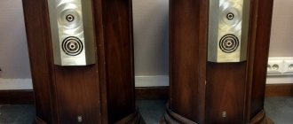
NA3 – 2-way speaker for 4 GD-35 + 2 GD-36
NA3 - Modest 50 liter shelf holders. Maximum quality at minimum costs
An article about the creation of na-3 loudspeakers was written several years ago. Given today's experience, I would approach their creation a little differently. I left the original text of the article practically unchanged. Modern comments and additions to the original text are highlighted in blue. Errors made during the creation of this model and the most important points are indicated in red.
Part one, introductory. How it all began
The idea to create acoustics based on the 4 GD-35 was born quite a long time ago, because, having heard them once as part of the Rigonda radio, I could no longer forget their sound. Of course, not only the speakers provided the characteristic sound of the legendary Soviet radio, but nevertheless...
Initially, the idea was to have screens or OYA (open box) with a frontal size of about 50x100 cm with mini subs on which these screens would be attached... But! These speakers provide adequate sound with a screen size of 100x150 cm, and even the “calculated” 50 cm width of the screen no longer fit into the size of the room.
This project remained a project and was archived under the name NA-2. I am still of the opinion that the NA-2 model is absolutely viable, the only question is the exact calculation of the OP that serves the mid-high frequency section. 25 GD-26 speakers may well be suitable as a low-frequency link .
Rice. 1. General design of NA2 speaker system:
Since the desire to make an acoustic system on these speakers has not diminished at all, I was not too lazy to stick an ARS (Acoustic Impedance Panel) on the windows of the basket and put the whole thing in the enclosures from my first NA-1 speakers (50 liters FI with dimensions of about 22 * 30 * 100 w*g*h). PAS was used to adapt a high-quality speaker to the conditions of a closed enclosure, without which the sound would be compressed and uninteresting.
First of all, I was surprised that with a rated range of 60-12500 Hz, these speakers reproduce music very seamlessly and completely, provide fairly high resolution, and sound emotional, expressive and lively. Having experimented with the FI (bass reflex) and even the ZY (closed box) options, I came to the conclusion that the existing cross-section of the FI pipes was clearly not enough, and I didn’t want to use housings from old speakers. Thus the drawing of the NA-3 model was born.
Rice. 2. Drawing of the NA-3 acoustic model:
Part two. Rationale and design features of NA-3
In the new speakers, it was decided to use walls made of natural wood followed by varnish coating, as well as pay more attention to sound and vibration insulation of the enclosures. The volume of the case was supposed to be about 50 liters, the FI was slotted, originally designed for speakers 10 GD-36 (which, in fact, are deeply modernized 4 GD 35) L = 21 cm, S = 67 cm2, subsequently the length of the FI was changed to 20.8 cm - the size indicated by Alexander Klyachin in the sketch of the housing for the 10 GD-36 - an action that was completely ill-considered, but as it seemed to me at the time, it was extremely wise (after all, if something happened, it would be possible to attach the same 10 GD 36, for which the bass reflex was designed, into these housings).
The decision to organize a FI, and even one designed for, albeit similar, but different dynamics, was, to put it mildly, naive. The LF depth reproduced by 10 gd 36 and 4 gd 35 differ noticeably from each other, so at least this should have stopped me. But it didn’t stop... The result turned out to be appropriate - FI provided a slight increase in bass due to its noticeable blurring. As a result, I use these speakers in the ZY mode (I simply plugged the bass reflexes with rags).
Now I would make the buildings according to this drawing. Rice. 3. Drawing of the NA-3 acoustic body:
I left the assembly description unchanged - as it was originally written for the FI type case. There are two reasons for this: firstly, the new body is simply simpler and once you understand how the FI is made, assembling the SF will not be a problem; secondly, in the process of assembling a housing with a slot-type FI, several specific problems arise, the solution of which was explained in the original text. So I leave everything as it was before. Comments on the new version of the corpus will appear in parallel with the old text.
The size and shape of the AC finally determined the dimensions of the available material: furniture panels measuring 100x40x1.5 cm, which were cut in half with a jigsaw (in the direction across the grain, at high speed, the cut of the wood is quite neat) and used as side walls. The design was initially designed in such a way that the thickness of the side walls could be arbitrary, so the material for the side walls could be taken of any thickness.
After cutting the furniture board, I was discouraged by the shape and size of the resulting blanks - it turned out that initially the boards were made with noticeable deviations from the declared dimensions, both in length and width, deviations reached +/- 3-5 mm. As they say, it’s unpleasant, but true, I had to carefully level the ends with improvised carpentry tools... The remaining parts were cut from 16 mm thick veneered chipboard - in my case, these were various parts from old cabinets.
Since not all the material was of high quality (and I’m not a good carpenter), it was decided to stick to the “antique” style, i.e. The speakers had to be initially shabby and “beaten by life” and look like the speakers, some of which turned out to be older than me. In order not to spoil the veneered surfaces with unaesthetic screw heads, I assembled the speakers on blocks, i.e. all the walls were attached to the bars with screws (with preliminary coating of the surfaces with glue) in such a way that all the screws were tightened exclusively from the inside.
The only wall screwed on from the outside is the front panel. The drawing shows that it is surrounded by walls on all sides, and during assembly, the seat for it is made so that it is slightly recessed into the body (2-3 mm) in order to hide the ends of the decorative trim covering the screw heads. The fact that the beam also falls into the FI gap prompted a recalculation of its cross-section. Taking into account the timber, its dimensions were 27x3 cm.
Pay attention to the relative position of the walls of the speaker body: the sidewalls cover a larger number of ends of the remaining parts (only two ends remain visible - the bottom and the lid, the rest are located on the back side), the front wall is completely recessed, and the parts surrounding it hide the ends of the facing surface ( leatherette, cork, etc.). That is, such a layout is the most win-win, especially for a novice carpenter-column maker.
Part three. Assembly order
First, all the blanks were cut. The outer vertical edges of the side panels were slightly rounded using a block of coarse sandpaper. Next, the workpieces were matched to each other and their most suitable combination was marked - thus, it was possible to compensate for deviations in their sizes from the calculated ones.
The next step is cutting and attaching the timber (item 8, Fig. 3) to the side panels using 3-4 screws and PVA glue. The most accurate location of the beam was obtained by simply applying the corresponding wall (for which I marked their best mutual combination); for greater accuracy, it is necessary to drill holes in the beam with a diameter slightly larger than the diameter of the screw and use screws with flat (rather than countersunk conical) heads. First, I coated the beam with glue and lightly screwed the beam with screws, so that it could be moved with difficulty (as far as the enlarged holes in the beam allow), and then, using the corresponding wall as a template, I pulled the beam into place.
We ensure smooth mating of the walls. The diagram shows the process of attaching the beam to wall B. The contact point between wall B and the beam is coated with glue. Wall A acts as a template (this should be exactly the wall that will subsequently be attached to this place). Applying wall A to the reference point, tighten the screws without tightening. The exact position of the walls relative to each other is established due to the gap between the screw and the hole in the beam (the beam slides along wall B). The beam is fixed by tightening the screws. After the glue has dried, wall A is attached (also with screws from the inside, coating the contact point between the timber and the wall with glue).
Rice. 4. The process of assembling the housing of the NA-3 speaker system:
As a result of these operations, we have sidewalls with a beam screwed along the contour of the future body.
In the inner rear wall we drill (or cut out) holes for the terminals; I chose terminals with a long screw, without a “trough” and limited myself to drilling two holes, and under the trough I would have to work with a jigsaw.
After that, I coated all the outer surfaces with varnish in order to eliminate the possibility of staining the surfaces of the workpieces with anything. The main thing is not to forget that the sides must be varnished both on the ends and (in some places) on the inside. I used quick-drying varnish, applied it with a brush in two layers with intermediate sanding of particularly rough areas (by the way, sanding before coating won’t hurt). Next day I endured the workpieces laid out on the floor so that they could dry thoroughly. I won’t say that it turned out very beautifully, but all the smudges and unevenness on the slightly scratched and chipped veneer fit well into the concept of “non-new” speakers. In general, I don’t pretend to be professional in this matter. For a more accurate varnish coating, apparently, you need to use some other, more cunning technique.
The body was assembled in the following order: the top wall (3), the outer rear wall (4), the inner rear wall (5) were screwed onto one of the sidewalls (1), the second sidewall (2) was screwed onto the resulting structure, then the bottom (6) and stiffening ribs (9) (it is inconvenient to fasten them in a half-assembled body, but if you screw the ribs on right away, it will be difficult to reach with a screwdriver to fasten the rear walls).
The stiffening ribs (9) in my case are a chipboard strip 5 cm wide and 45 cm long, screwed onto the side walls, naturally from the inside (they are shown in blue in the side view). Here and further: Stiffeners, in principle, can have any shape, material and location, the main thing is that they perform their main function.
In the new version of the housing, the function of stiffening ribs is performed by a partition, so there is no particular need for additional stiffening ribs on the side walls. The places that need to be strengthened are the back, top and bottom walls. Everything about the front panel applies equally to both types of housing. One important nuance: In order to screw the outer rear wall with a screw, you must first drill a hole for a screwdriver in the beam for fastening the inner rear wall, as shown in the sketch with a red arrow.
After assembling the case, I prepared the front panel (7): placing it in the case, I marked the center for the holes for the speakers (I measured everything relative to the outer dimensions), cut out the holes with a jigsaw, and screwed (with glue) the stiffeners (9) onto the inner surface.
And then the most interesting thing began - vibration isolation. For these purposes, I stocked up a rubber-based carpet and 2 kg of window putty, which in appearance and composition is very similar to ordinary children's putty. Initially, it was planned to apply bitumen mastic, but the risk of staining the outside of the body and the likelihood that the mastic would dry (and therefore smell) for many months prompted me to use putty. The option with putty, as it turned out, is also not ideal, but quite acceptable, especially at home. And so, let's apply it.
First, I generously coated all the corners, and then applied it in an even layer to all internal surfaces. The thickness of the layer was about 2-3 mm, the available 2 kg was only enough for one speaker, and unfortunately the next 2 kg of putty turned out to be much harder, and we had to first cut it into thin (2-3 mm) strips and either heat it with a hairdryer or knead in your hands into small pieces (the size of a large hazelnut). Subsequently, it turned out that solid putty is the most suitable option, because... the smell of the softer one was felt for quite a long time, especially if you were close to the speaker.
Hence the moral: before using the material, it is worth checking how it will behave over time. My hopes that the smell would disappear quickly were justified for a very long time. After coating, pieces of carpet of appropriate sizes were cut out and secured with the rubber side to the walls using a furniture stapler (the surface of the putty was previously heated with a hairdryer. The stapler had to work a lot, it took about 1100–1200 staples (i.e., the carpet was “shot” in increments of about 2 -3 cm over the entire surface).
This was done to connect it with the body as tightly as possible, otherwise it would have been just soundproofing. After the stapler, just in case, I tapped all the surfaces with a hammer for better bonding with the putty and deeper driving of the staples. After a while, I thought it would be worth inventing some simpler method, for example, simply gluing the carpet with the rubber side to the surface of the wood (chipboard) using “Moment” or something similar. Yes, perhaps, rubberized carpet + “Moment” is not so bad, and much easier to implement (the main thing is to do it in the air). Another option is to stick linoleum (the one with the “hairy” underside) to the “Moment” using the same principle.
Sound insulation was provided by thick (5 cm) padding polyester “targeted” with a small number of paper clips along the entire inner surface (the main thing is not to close the FI). Later, after installing the speakers in the housing, an additional piece of fluffed synthetic padding is placed inside. Perhaps the phrase “a piece of fluffy padding polyester” does not accurately describe the correct approach to filling the volume. It is necessary to tear the padding polyester into small pieces of air and easily fill the entire volume with them, without using them (in a FI-type case it is necessary to ensure free access of air from the bass reflex port to the speaker, and we fill the ZY entirely in the literal sense of the word). I had the idea to abandon the PAS, compensating for this by filling the body, but the best option was the combination of the initially selected PAS and light air filling of the volume with padding polyester. A clever partition in the new version of the housing will prevent the filler from creasing.
After sound and vibration insulation is completed, the front panel is installed in the body (also glue and screws) and the seams are sealed from the inside. The countersinks in which the screws are recessed are covered with putty or a mixture of PVA + sawdust. After drying, all unevenness is sanded (it is not ideal to remove it, because under a layer of leatherette, small unevenness is not visible). Marked for the screws used to secure the speakers. After this, using a sharp knife and a long ruler, carefully, with constant fitting, a suitable piece of leatherette is cut out and glued to the “Moment” or something similar. Plan B in this case was to use sheet cork. But leatherette, in addition to its aesthetic charms, has one small technological advantage - during the gluing process it stretches a little and it is possible to correct mistakes made during cutting.
Part four. Electric
On the windows of the speaker basket 4 GD-35, as I already mentioned, with the help of the same “Moment”, a PAS was glued - one layer of synthetic polyester (5 mm in uncompressed form). Another trick: you need to glue the existing sound-vibration-insulating material to the inner surface of the speaker basket. This reduces the reflections of the sound created during the reverse stroke of the speaker. And to the ear this is expressed in a cleaner and clearer sound. Personally, I lined the inside of the four “supports” that form the windows of the basket with small pieces of short-pile faux fur, but any material from thin felt to carpet will do for this purpose. When pasting, the main thing is that it does not interfere with the operation of the speaker (does not come into contact with the diffuser when it moves). And after gluing the inside, we glue the PAS on the outside. 2 GD-36 (version with a resistance of 8 Ohms) as the HF link It requires a 1st order filter. According to initial calculations and subsequent selection of the nominal value by ear, a value of 2.4 μF was obtained. Important: this value is applicable only when working with transistor amplifiers; when connecting to a tube device, reconfiguring the speaker data is required!
There is no such rating as standard, so we had to use several capacitors connected in parallel (for example, 2.2 and 0.22 μF). The type of capacitors is K73-16 (voltage is not as important as accuracy), they practically do not spoil the sound, unlike inexpensive imported ones. An even more affordable option is K73-17. It seemed to me not justified to buy anything expensive, given the fact that not all expensive parts have sound corresponding to the price. It is possible that among those available you will come across an even more suitable sounding option. In any case, it is necessary to remember that film capacitors have a pronounced directionality; it can be heard by connecting it together with any good-sounding speaker in series with the amplifier and “turning” the capacitor. In order not to go far, you can assemble the speaker by turning on only 4 GD-35s and listening to it through a capacitor turning it on in different directions. The difference in sound is similar to the difference in the sound of a cable connected in the forward and reverse directions.
Rice. 5. Filter diagram of the NA-3 speaker system:
I simply soldered the capacitors with one paw to the positive terminal of the tweeter. Although I probably should have attached them to the input terminals, as is traditionally done, it was convenient for me to simply keep the capacitors on the speaker because I soldered them three times a day... The figure literally shows how the speakers are connected. The connection in which the signal for the high-frequency link is removed from the mid/low-frequency speaker (“loop”) has been tested and has noticeably worse sound.
The selection of the type and cross-section of wires was determined by ear. As a result: the speakers are supplied with a homemade Litz with 75 wires in the conductor, the wire diameter is 0.18 mm. At that moment, I believed that when working with Litz, it was the cable cross-section that mattered. Now I would put Litz 34*0.18 there, each core of which should be in one layer of paper. Have you read everything? And now the latest option - look for something even more correct-sounding than a homemade litz, and these searches will be rewarded with a more pleasant and accurate sound. The wiring inside the equipment is no less important than any other element. The option with Litz 34x0.18 is good, better than many cheap cables, but you can get more quality from these acoustics if there are decent wires inside it. Which? I won’t give a definite answer, since I don’t have much experience working with ready-made cables. In my case, the best sound as an acoustic cable (as well as the wiring of the output and power circuits inside the amplifier) was obtained from a copper monocore in polyethylene insulation (the colored cores are from a thick telephone cable). With a monocore diameter comparable to the diameter of a modern twisted pair, the number of conductors in the finished core should be about 4–6 pieces. We determine the optimum by ear by listening to different numbers of monocores as an acoustic cable (the speakers at this moment can be separated by any more or less decent wire without pronounced sound distortion).
Later, instead of 2 GD-36, a 6 GDV-5D , which has similar frequency response and impedance, but more power. The sound has changed for the better (there is more “air” and transparency), but the character of the sound remains the same cozy and relaxed. There are also speakers model 6 GDV-2-8 , but their sound turned out to be unsatisfactory. After some time, I can add that the old 2 GD-36s are still a little livelier, more pleasant and expressive, and the new 6 GDV-5Ds play a little less soulfully, but provide the necessary amount of high frequency. The compromise is quite acceptable; there was no desire to supply 2 GD-36s. I am writing about this solely for the sake of fairness.
Part five. Final. Two in one...
As a result, we have expressive, musical speakers with some lack of bass (in my opinion, a sub is still needed, although even without it the music sounds very good and full). This model has high resolution, soft high frequencies, sounds comfortable and lively, conveys emotions and intonations quite fully, especially compared to modern speakers in the lower and middle price ranges, not to mention stereo systems and other boomboxes. The design reveals the capabilities of a good wideband speaker, adds a high-frequency component without damage, and allows you to achieve unexpected (for a speaker with a lower limit of 60 Hz) depth and fullness of low frequencies.
After a couple of years, I can confirm that the speakers turned out really good. During this time, I managed to demonstrate their sound to many and listen to my acoustics with various amplifiers and sources. In fact, in this design I managed not to spoil the initially excellent sound of the speaker, ensure tolerable dimensions of the cabinets and obtain a fairly wide effective frequency range. It is difficult to compare these acoustics with branded ones - from the point of view of a music lover, the na-3 is much more attractive than most branded speakers in the range of up to $500, since they reveal the emotional and artistic content of music much more accurately and completely.
As for the passport characteristics, they look something like this:
- Power: 4 W (by modern standards, about 8-10 W of nominal power and 16-20 peak power, this power is more than enough for comfortable listening to music)
- Reproducible frequency range: 60 – 20,000 Hz (the upper limit of the HF is difficult to estimate, but the bass is easier - a flat frequency response starts at about 55 – 60 Hz)
- Sensitivity 90 dB
- Resistance 4 ohms
- Overall dimensions 30.5x40x50 cm (WxDxH)
Best regards, Naumov Maxim .
Price matters
If you look for such a device in online stores and compare its cost with imported analogues, you will find that it simply has no competitors. After all, foreign samples cost tens of times more. Therefore, many lovers of good music will simply turn a blind eye to weak lows and minor distortions in the frequency response. Despite the fact that 4GD-35 is not a scarce commodity. You can purchase it in many audio equipment stores or, for example, on the Avito classifieds website, for relatively little money. The price of one speaker fluctuates around 500 rubles.