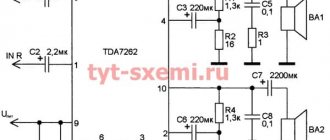
Microprocessor audio switch
The PIC16F84 microcontroller contains a control unit that polls the switching direction selection button S1, generates control signals for the CD4052 chip and indicates the current state using the HL1 LED. The clock frequency of 3.5 MHz is not critical and can be selected anywhere from 3 to 4 MHz. The microcontroller firmware program files are available on the magazine's website. The TPA6110A2 chip is used to assemble a high-quality stereo headphone amplifier. The need for an amplifier is due to the fact that the signal from the output of a computer's sound card is not always able to provide sufficient volume in passive headphones. The amplifier operates with a gain of 1, but if desired, the gain can be easily increased by decreasing the resistance of resistors R9 and R10. The amplifier is designed to work with headphones with an output impedance of at least 16 Ohms. The amplifier's THD is less than 0.03% at 1 kHz. The TPA6110A2 amplifier chip (Texas Instruments) can be replaced with the LM4881 chip (National Semiconductor). When assembling the device, pay special attention to the correct wiring of the power and ground lines.
When you turn on the device, audio output 1 always becomes active. By successively pressing the S1 button, you can connect other audio outputs “in a ring”: 12-3-1-2-.. . Connection of the next output is accompanied by a single sound indication, and the number of sound signals given corresponds to the output number. The LED constantly indicates the number of the connected output with the corresponding number of short flashes with a pause between series. For ease of use, the S1 button can be moved outside the case and placed in a convenient place, while the switch itself can be placed closer to the location where the connectors of the switched audio equipment are concentrated. A free USB port on the computer is used as a power source. The total current consumed by the circuit does not exceed 10 mA. This switch can be easily upgraded to expand its capabilities. The presence of free microcontroller ports allows you to complicate the indication circuit, for example, by installing individual LEDs to indicate the connection of each output. To increase the number of switched outputs to 4, it is enough to add a connector and connect it to lines 11 and 4 of the CD4052 microcircuit (with a corresponding change in the program). Current consumption can be significantly reduced by eliminating the LED indication and using the interrupt mode by pressing the S1 button. If you abandon the amplifier on the D3 chip and optimize the operation of the generator (turn it on for a short period to charge C7), then you can build a battery-powered switch. In this case, a set of three AA size alkaline batteries will be enough for several years of continuous operation of the switch. Another direction to improve performance is to replace the S1 button with control using an IR remote control or via radio. The microcontroller's computing resources are sufficient for all of the above improvements.
Quartz 3.5MHz CPU: PIC16c84 (PIC16F84A, PIC16F84) CP OFF, WDT OFF, PWRTE ON, XT OSC
Прошивка: :020000040000FA :020000000528D1 :0800080037298316173081002F :100010000F308600E23085008312850186010D21B4 :10002000ED20E6201A211A211A2106128612051542 :10003000EF20851C4728EF20851C47280511EF205D :10004000851C4728EF20851C4728EF20851C472862 :10005000EF20851C4728EF20851C4728EF20851CB2 :100060004728EF20851C4728EF20851C4728EF20D4 :10007000851C4728EF20851C4728EF20851C472832 :10008000EF20851C4728EF20851C47281528E620EF :100090001C211C21EF20EF201C211C21061286169A :1000A0000515EF20851C8E28EF20851C8E28051154 :1000B000EF20851C8E28EF20851C8E280515EF204B :1000C000851C8E28EF20851C8E280511EF20851CAD :1000D0008E28EF20851C8E28EF20851C8E28EF208F :1000E000851C8E28EF20851C8E28EF20851C8E28ED :1000F000EF20851C8E28EF20851C8E28EF20851C84 :100100008E28EF20851C8E28EF20851C8E28EF205E :10011000851C8E28EF20851C8E284E28E6201E2167 :100120001E21EF20EF201E211E21EF20EF201E2197 :100130001E21061686120515EF20851C1128EF20BA :10014000851C11280511EF20851C1128EF200515AD :10015000EF20851C1128EF20851C11280511EF20A8 :10016000851C1128EF200515EF20851C1128EF2094 :10017000851C11280511EF20851C1128EF20851CF6 :100180001128EF20851C1128EF20851C1128EF2055 :10019000851C1128EF20851C1128EF20851C1128B3 :1001A000EF20851C1128EF20851C1128EF20851CCD :1001B0001128EF20851C1128EF20851C1128EF2025 :1 001C000851C1128EF20851C1128992806168616F3 :1001D0000800C830F3286430F3283230F3280A309E :1001E000F3280530F3289100F820910BF428080 03B :1001F00008308F00F930900064006400900BFC28F8 :100200008F0BFA28032964000800F8308F0064007F :100210008F0B07290B29640008001A211A 21EF20EF :100220001C211C21EF201E211E21EF202021202136 :10023000202108004130222937302229303022295C :10024000243022298C0023308D00051 42E212829EA :10025000000005102E218D0B252908000C088E00AA :1002600031293229332934298E0B3029080009001D :02400E00F93F78 :00000001FF
MODERN ELECTRONICS No. 6 2006
Audio switching and indication
Selector circuit for four audio inputs for a stereo amplifier
The circuit is designed to switch four inputs of a stereo amplifier electronically, using a double multiplexer K561KP1. The K561KP1 microcircuit is a functional analogue of a switch with four positions and two directions. And the “handle” is a two-digit binary...
1 155 0
Galvanically isolated audio or video signal input
Galvanic isolation of audio and video inputs was used in small-sized SONY TVs with transformerless power supply. A small-sized transformer was installed in the audio signal circuit, and an optocoupler was installed in the video signal circuit. Rice. 1. Schematic diagram of an audio/video signal input with galvanic...
1 40 0
Active audio signal splitter using field-effect transistors, circuit
In amateur practice, in addition to mixing audio signals, it is often necessary to solve the inverse problem - branching into several consumers. To ensure isolation between consumers, it is best to use an active splitter. Rice. 1. Schematic diagram of an active audio splitter...
1 19 0
Diagram of an audio and video signal switch for three channels
Input A/V signals come from three sources to the “tulip” blocks X1, X2 and X3. To switch audio signals, the K561 KP 1 chip is used, which is a multiplexer of analog and digital signals. This circuit uses six of the eight channels of this chip...
0 905 1
Automatic switcher of audio and video signals
Schematic of an electronic signal switch that provides simultaneous switching of audio and video signals from two different sources. This avoids the hassle of repeatedly disconnecting and reconnecting the connectors of these devices. A significant portion of inexpensive inexpensive...
1 1053 0
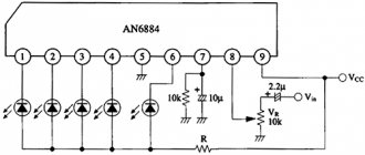
Stereo signal level indicator on two-color LEDs (AN6884)
In homemade stereo amplifiers, radio amateurs often use LED signal level indicators on microcircuits like the AN6884. Such a microcircuit contains an input amplifier - a detector and five comparators with outputs to LEDs. Level indication - the length of a line of five LEDs...
1 925 0
Diagram of a 12-level low-frequency signal indicator on the ATtiny15L
Homemade LED scale indicator of low-frequency signal level at 12 levels. Indication is carried out on a 12-level LED scale HL1-HL12 using the luminous dot (DOT) or luminous line (BAR) method. Rice. 1. Schematic diagram of a 12-level signal indicator for an amplifier...
0 1397 0
Indicator circuit on AN6884 chip, moving dot
Nowadays, LED scales such as a luminous column (bar) or a moving dot (dot) are often used to indicate the level. Microcircuits like LM3914-16 are convenient, they have ten indication thresholds and you can choose the type of indication - bar or dot. But simple five-threshold chips like AN6884 (or...
0 1336 0
Audio Peak Indicator Circuit (CD4093)
The figure shows the peak meter circuit for the output of a stereo low frequency amplifier. Schmitt triggers D1.1 and D1.2 are used as comparators. The indication threshold is set by adjusting the DC bias voltage with resistor R1.
2 1328 0
Electronic switch for four audio inputs (IE8, KT3102)
The device is designed to switch two low-frequency signal circuits to four positions. This could be switching between four stereo amplifier inputs and four video and audio sources for the TV to, for example, choose between a satellite receiver, games console, DVD player and...
1 2751 0
1
The situation for which this switch was developed was the following: there is a certain room where a sound reproduction system is installed that continuously plays music from a computer (PC), but there is also another signal source - a television (TV), and accordingly, when a sound signal appears at its output , the system should switch to playing TV sound.As can be seen from
, the control for the switch is the signal of the right channel (R), coming from the TV, it is fed to an amplifier made on the basis of an op-amp - U1A. The gain of this stage, necessary for accurate operation of the device, can be adjusted using the trimming resistor RV1. Next, the amplified signal is fed to a voltage rectifier circuit made on elements C2, D1, D2, C3.
The rectified voltage is used to control transistor Q1, in the base circuit of which there is a tuning resistor RV2 connected in parallel with the electrolytic capacitor C3; with this resistor you can adjust the “reverse” switching time, i.e. the time after which the switch will return to PC mode after the control signal disappears. It is necessary to select the optimal “reverse” switching time so that it is not too long - for example, the sound from the TV is no longer received, and there is still no music from the PC, and it is not too short - in this case, the switch can switch to PC mode even for pauses in the TV soundtrack.
From collector Q1, the control signal, to be converted to a “digital” form, is supplied to the input of an inverter with a Schmitt trigger - element U3E. Switch SW1 allows you to select the operating mode of the device - automatic, or manually turning on the TV mode. The basis of the switch is the U2 4053 chip (CD4053, KR1561KP5), which consists of three bidirectional analog switches (only two of them are used - X and Z). Control is carried out via inputs A (11) and C (9) combined together; the enable input for the switches of the microcircuit Inh (6) is connected to a common wire. When working with analog signals, for the 4053 chip, it is necessary to use a negative voltage source - pin VEE (7).
The switch is powered from a simple bipolar source, made according to the following circuit: a 6-0-6V / 500mA network transformer, four FR103 diodes, two 2200uF/16V electrolytic capacitors, integrated stabilizers such as L78L05 and L79L05.
Operational amplifier U1A - LM358M, in SO8 package (only one amplifier is used out of two available in the case); microcircuit U3 - type 74HC14, in SO14 package (inputs 1, 3, 5, 9 of unused elements of this microcircuit, you must connect to its output 16 - “+” supply voltage); miniature type 3329H were used as tuning resistors RV1, RV2; all fixed resistors are SMD (0805); electrolytic capacitors C2, C3 - any of suitable dimensions; capacitors C1, C4, C5 are ceramic SMD (1206).
The circuits of the switch and its power supply are mounted on sections of a breadboard, placed in a plastic case of the Gxxx type; the connectors for input and output signals are of the “tulip” type, located on the rear panel of the case. The SW1 switch and the power-on indicator LED are located on the front panel.
This scheme was developed in a relatively short time, using components that were, as they say, “on hand,” so there are some “ugliness” and suboptimalities in it, but nevertheless, the device was made and is being used quite successfully.