In signal processing tasks, there is often a need to filter signals when the signal is divided into narrow-band ranges. In everyday life, we encounter this when playing music through acoustic systems, in which each loudspeaker (speaker) reproduces its own frequency band, of which there are usually three - low (LF), medium (MF) and high (HF); To reproduce ultra-low frequencies, a separate acoustic system called a “subwoofer” is sometimes allocated. The specific frequency boundaries are implementation dependent and are roughly at the boundaries of 100 Hz, 1 kHz and 5 kHz. In order to avoid sharp jumps in volume between speakers, partial overlap is used - when the amplitude of the reproduced frequency band smoothly decreases on one, while simultaneously increasing on the other. The most popular filters for such a partition are Linkwitz-Reilly filters of the 4th order, which are two Butterworth filters connected in series, the image of the frequency response of which is familiar to many:
Their popularity is due to the simplicity of circuit implementation and smooth frequency response with the absence of pulsations. The filter order, which determines the decay rate, is usually chosen as 4th.
All analog filters have disadvantages - instability of parameters and difficulty in setting up. Another important drawback is the irreparable phase shift. It is impossible to implement a phase-linear filter in analogue, because this violates the cause-and-effect relationship between the output signal and the input signal.
The advent of digital technology in general and digital signal sources in particular made it possible to get rid of the shortcomings of analog filters by implementing them directly in software, in digital form. This approach requires "multiamping"—using a separate power amplifier for each frequency band—as opposed to the classical approach of first amplifying a broadband signal, which is split into frequency bands by (usually) passive filters. The use of several amplifiers instead of one obviously increases the cost of equipment, so this solution is chosen for particularly high-quality systems.
▍ A Brief Introduction to Digital Filters
A digital filter is a function that can be viewed in both the time and frequency domains.
In the time domain, it determines the impulse response obtained during the reaction of a certain device or its mat. models for a single impulse (heard as a click). In the frequency domain, it determines the amplitude attenuation or amplification and phase shift at a particular frequency. The transition between these domains (in English literature the word domain is used) is carried out through the Fourier transform, which sets a one-to-one correspondence between functions in the time and frequency domains. There are two types of digital filters:
IIR (Infinite Impulse Response)
— filters with infinite impulse response. In essence, they are the same analog filters, but “modeled” digitally - the mathematical apparatus in both cases is identical (which is based on the Laplace transform). This implies the infinity of the impulse response, which can be represented as a sum of exponentially damped sinusoids.
This is what the impulse response of a high-Q recursive low-pass filter looks like (cropped to the right)
Their advantage is low computational complexity - each new value is calculated recursively depending on the previous ones. They are also sensitive to calculation errors and rounding errors - therefore, the issue of stability (guaranteed attenuation in the absence of an input signal) of such filters is considered separately in theory.
The simplest is a first-order low-pass filter:
FIR (Finite Impulse Response)
- filters with finite impulse response. The most famous filter of this kind is the moving average, and the filtering itself is carried out by linear convolution of the filter samples with the input signal samples. Here the complexity is already quadratic - however, it can be reduced to , if you use a fast convolution algorithm using the fast Fourier transform (FFT). The finite number of samples imposes its limitations on the shape of the frequency response, leading to pulsations.
Note
In fact, mathematically, both IIR filters and FIR filters are described in the same way - through the ratio of polynomials.
The difference is that for IIR filters the degree of both the numerator and the denominator is small, while for FIR filters the high degree of the numerator compensates for the unity denominator. This topic is quite complex and occupies a considerable part in the theory of signal processing; For practical problems, it is not necessary to go deep into it, but for those interested, we can recommend remembering the Taylor series, then moving on to the generating function and then dealing with the z-transform. And this is what the impulse response of a phase-linear FIR low-pass filter looks like
A fairly popular practice when designing filters is linearization - when the frequency response of a known IIR filter is taken and an FIR with linear phase is formed from it.
Again about a simple active filter for speakers
Quote: Chugunov
It's a funny situation - people catch hundreds in simulators... further in the text
Greetings Sergey!!! Agree that you have now written many non-absolute truths. Look here: Apparently, in the original circuit, the speakers should be turned on in antiphase (for some reason I forgot about this possibility and sought coordination when turned on in phase). -This only applies to phase matching of the voltage at the filter output. What will happen with real speakers is another question.
It’s a funny situation - people catch hundreds in simulators, forgetting that it’s not individual filters that work, but the whole system: filters, amplifier, acoustics. It turns out, like Raikin: “Do you have any complaints about buttons?” They are silent about the fact that the simulators assume that the speakers are ideal (a spherical horse in a vacuum) or at least all the speakers cover the crossover frequency of two octaves with good linearity (ha ha ha). -There is no point in even sculpting a crooked filter onto crooked speakers from the start. The simulator is not a panacea, and no one really catches fleas. It’s just much easier to figure it all out in order to avoid obvious mistakes. In my opinion, it is mandatory to adjust the filters on the entire system with standard amplifiers and acoustics using a measuring microphone, otherwise there will be no complaints about the buttons, but in general... that’s only later, but first it would be advisable to make everything else workable. And then there’s the fine-tuning.
I think any filters are evil. -I don’t know, try to get by. The problem of choice is how to choose the least common evil. -I can't argue with that. This is a philosophical question. It is known from theory that the steeper the frequency response of filters, the worse their phase response. Probably, it is necessary (when striving for perfection) to try different options. -What theory is this?? And how can the phase response of filters be worse or better? The phase response of filters (in terms of voltage is simply an inclined line with varying degrees of inclination). Another thing is the total phase response of 2 or three filters working together for one load. That's how it should be said. Is it known that FCHH is not everything? 1st order filters also have a lot of disadvantages, for example, the directivity at the crossover frequency is wildly curved (compared to higher even order filters). And this has no less impact on quality.
I think the greatest positive effect from active filters will be for mid-level systems (of which the absolute majority). I think this filter has every right to exist and will improve the quality and capabilities of most systems. — Genelek active acoustics have active filters. And she is very high class. PS It’s funny that a progressive block system with the principle “we connect any amplifier to any speakers” is backfired today. In the past, when we bought a decent sound system, including amplifiers and speakers, we had parts that were optimized to work together and were guaranteed to work well. Today you can cube separate expensive cubes that will not work well together. -Nobody ever said that “cubes” are universal. Only to some extent and with the right selection. The equipment is always matched to each other, this has been and will be. Even something that was all in one and configured at the factory may not sound good in a bad room. And not all equipment was previously designed and configured with love, oh, not all.
▍ Statement of the problem
So, our task is to form a pair of filters that divide the frequency band into two with overlap. At the same time, they must have the following characteristics:
- Smooth frequency response without pulsation;
- Phase linearity (phase shift at all frequencies is zero);
- Symmetry of the frequency response on a logarithmic frequency scale.
Note
point 1) means that we do not put ripples into the filter in the same way as is done, for example, in the Chebyshev filter.
In theory, a perfectly smooth frequency response is only available in an infinite-length IIR filter. In practice, we only need to ensure that the ripple level does not exceed the noise level of the input signal, which for audio signals is -120 dB in general and -90 dB for CDs and other 16-bit recordings. The symmetry (mirrority) of the frequency response solves two problems: 1) the high-frequency component of the signal can be obtained by subtracting the low-frequency component from the original one - both in the frequency and time domains;
2) eliminates the painful choice of which filter - low-pass or high-pass - is preferable to a flatter or steeper slope of the frequency response. A similar requirement exists for quadrature mirror filters, in which symmetry is specified on a linear frequency scale. But we are interested in the logarithmic scale, as it is more natural for human hearing.
Besides,
The style of presentation in the description of quadrature mirror filters, whether on Wikipedia or in typical scientific works, does little to help even a programmer not very far from mathematics understand how they need to be implemented in practice.
The “three-strip” project and the influence of parts in the AC filter
January, thanks to the holidays, turned out to be fruitful for creativity - I finished my “three-stripe” project, which lasted for several years. I would like to share the results and propose to discuss two important points: the difficulties in organizing a listening space and the influence of details in the speaker filter.
I have rather difficult acoustic conditions and do not have a separate listening room. I was not at all sure what would happen, but the “senior comrades” helped with valuable advice and recommendations in choosing heads, for which I am very grateful. That is why the choice of heads is not accidental.
Morel 328 + ScanSpeak D7608 is a proven combination, and I like the Wavecor WF182BD for its low distortion. The result turned out to be predictable and relatively little time was spent on creating the speaker system. Body – MDF in white varnish, three stripes, bass reflex, weight 42 kg (each). The sound is very open and large-scale. There’s not a lot of bass, but I didn’t set the goal of getting a thunderous low end; what’s more important is to “make friends” with the speakers in the room. I think that they will sound comfortable in a relatively large room. One of the advantages in this project is the middle. And she's very good.
I had heard dome midrange drivers before, so there was a desire to use these particular drivers. There was also a condition that it was impossible to align the acoustics with the listener; the speakers were forced to stand strictly parallel. In general, I decided to take a rather unpredictable path - using not one large speaker in a three-way system, but two relatively small ones. I think that it is precisely this arrangement of the heads, vertically relatively low from the floor, that allows us to solve the problems of a room that is difficult for acoustics.
I spent a lot of time on my appearance. I decided to choose a white color so that the acoustics would not look huge and would please me with its appearance even when turned off. The result was a project like this with the “wrong” placement of speakers in a complex room. I'm still waiting for spikes, maybe I'll lay down slabs. But the main thing is that jazz, old rock and vocals sound very good.
Frequency response from 1 m without smoothing (we need the truth) and impedance
Now I wanted to talk about the influence of capacitors and coils in the filter. I previously wrote that I did a project in a prototype case using Morel CAW 638 and ET 338 heads. Currently, all this is assembled into a “presentable” case and I installed MKP Mundorf MCap Supreme in the filter on the HF head, instead of the previously used white MKP Mundorf MCap , and a Mundorf M-Coil CF CFC16 17 mm inductor is installed on the LF-MF.
The result of using such details is very clearly audible. But control measurements of the frequency response and impedance did not reveal any changes. But the saxophone and vocals acquired new “touches”; one might say that they became more tangible, the “physicality and contrast” of the images increased. S. Zhilin began to sound with new shades; it was in his compositions that some kind of versatility was revealed, which was not previously noticeable. Honestly, I didn't expect such changes in sound. I've tried Mundorf MCap Supreme with the ET 308 before, but it was with the ET 338 that it showed up so clearly. I have never used foil coils before and can’t compare them with other low-frequency/mid-range heads. I think that these kinds of premium coils and capacitors can reveal the capabilities of very high-level heads. But, with relatively budget ones, this may not be noticeable.
▍ General construction algorithm
There are several approaches to designing FIR filters, of which the simplest and most intuitive is the following:
- In the frequency domain, the desired frequency response of the filter is set;
- The inverse Fourier transform is performed:
- A window function is imposed.
It can be performed both purely analytically and numerically using the discrete Fourier transform (hereinafter FFT). The analytical solution is more complex and has the obvious limitation of using only those functions for which Fourier transforms are known.
▍ Analytical solution
The Linkwitz-Reilly filter meets the above requirements of smoothness and symmetry (but not phase linearity).
Knowing the frequency response formula, where is the order of the filter, the impulse response formula can be obtained analytically through the Fourier integral, and specific samples of the FIR filter can be considered as its direct calculation. Logarithmic filter plot:
The best way to calculate the Fourier integral is to use some kind of computer algebra system. For example, in Wolfram Mathematica it would look like this:
InverseFourierTransform[1/(1 + w^2), w, x] // FullSimplify ↓
Graph of the resulting function, also known as the impulse response:
As can be seen from the formula and graph, the impulse response is infinite - it tends to zero, but does not reach it; and also symmetrical about zero (due to phase linearity). It is limited in time by multiplying by the window function, due to which the function values outside the window acquire zero values, which do not require participation in calculations. A side effect of this is the distortion of the original spectrum of the filter - since when functions are multiplied, their spectra are collapsed. The resulting spectrum can also be seen through the Fourier transform. For example, for a rectangular window we get
as a result of which the frequency response of the filter will change to
code
FourierTransform[E^-Abs[x] Sqrt[Pi/2] UnitBox[x/5], x, w] // FullSimplify ↓
The ripples that we see are a consequence of the presence of “side lobes” of the window function.
They can be reduced by taking a smoother and wider window. Among the many developed windows, one of the most optimal and convenient for analytical calculations is the Nuttal window, defined as Note
Using Chebyshev polynomials, the Nuttal window can also be calculated as , where
Multiplying it by the impulse response of the filter, we obtain:
and the frequency response will take the form
code
frnw = FourierTransform[E^-Abs[x] Sqrt[Pi/2] NuttallWindow[x/20], x, w] // Simplify ↓
As can be seen, the magnitude of the pulsations has decreased significantly.
The graph shows that the filter shelf has dropped slightly - ideally, this should also be taken into account and compensated for. In this case, it was (at zero frequency): FourierTransform[E^-Abs[x] Sqrt[Pi/2] NuttallWindow[x/20], x, w] /.w->0.0 ↓
The imaginary part here was obtained due to an error in numerical calculations and can be safely discarded (this is indicated by the value, since the accuracy of the calculations is in double format and represents approximately 16 decimal digits).
In a similar way, you can calculate impulse responses for higher (but only integer) orders, for example:
InverseFourierTransform[1/(1+w^4), w, x] // FullSimplify ↓
As you can see, automatic simplification is no longer enough and manual work is required to bring the formula to a readable form. The result is the following formula (in complex numbers) for the impulse response of a Linkwitz-Reilly filter of arbitrary order:
When calculating by adding complex conjugate numbers, the imaginary part is set to zero and the result is a purely real function. This formula can also be written directly in real numbers:
Acoustics of computer speakers
I happened to watch a video on YouTube: a young man announced that he would make an acoustic system with his own hands. The boy is talented: he ripped out the speakers of his personal computer - well, none at all - brought out an amplifier with a regulator, and placed it in a matchbox (speaker system housing). Computer speakers are notorious for poor bass response. The devices themselves are small, light, and secondly, the bourgeoisie saves on materials. Where does bass come from in a speaker system? The young man took... read on!
The most expensive component of a music center. Hi-end acoustics cost less than a cheap apartment. Repairing and assembling speakers is a good business.
The low-frequency amplifier of the speaker system will be assembled by an advanced radio amateur; no Kulibins are needed. The volume control knob sticks out of the matchbox, the input is on one side, the output is on the other. The speakers of the old sound system are small. The young man got hold of an old loudspeaker, not of fabulous size, but solid. From a Soviet-era speaker system.
To prevent the sound from disturbing the air with squeaking, the clever youth nailed together one-inch boards into a box. The speaker of the old acoustic system was placed in the size of a mailbox, moved, as is done by the manufacturers of modern home theater subwoofers. I was too lazy to decorate the inside of the speaker with soundproofing. Anyone can use batting or other similar material for the acoustic system. Small speakers are placed inside oblong boxes that just contain a loudspeaker at the end. The proud youth connected one channel of the speaker system to two small speakers, the second to one large one. Works.
The young man is a fabulous fellow, he doesn’t drink in the gateway, like his peers, he doesn’t spoil future brides in his free time, he’s busy with business. As one acquaintance said: “The younger generation is forgiven for a lack of knowledge and experience, not an excess of arrogance, strengthened by indifference.”
Improvements
We decided to improve the method; we sincerely hope that the addition will help make the acoustic system itself somewhat better. Problem? The concept was invented by radio engineers and creators of acoustic systems - frequency. The vibration of the Universe has a frequency. They say that it is even inherent in a person’s aura. It’s not for nothing that every good speaker can accommodate several speakers. Large ones are intended for low frequencies, bass; others - for medium and high. Not only the size, but also their structure is different. We have already discussed this issue and refer those interested to the written reviews, which provide a classification of acoustic systems and reveal the operating principles of the most popular ones.
Computer scientists know the system buzzer, which operates via a BIOS interrupt, which seems to be capable of producing one sound, but talented programmers wrote elaborate melodies on it, even with an attempt at digital synthesis and voice reproduction. However, such a tweeter cannot produce bass if desired.
Why this conversation... A large speaker should not just be adapted to one of the channels, but should be given a specialization for bass. As you know, most modern compositions (We don’t take Sound Around) are designed for two channels (stereo playback). It turns out that two identical speakers (small) play the same notes, this makes little sense. At the same time, from the same channel, the bass is lost, and the high frequencies die on a large speaker. What should I do? We propose to introduce passive bandpass filters into the circuit, which will help split the flow into two parts. We take the diagram from a foreign publication for the simple reason that it was the first one that caught our eye. Here is a link to the original site chegdomyn.narod.ru. The radio amateur copied it from the book, we apologize to the author for not indicating the original source. This happens for the simple reason that he is unknown to us.
So, here's the picture. The words Woofer and Tweeter immediately catch your eye. As you might guess, this is, respectively, a subwoofer for low frequencies and a speaker for high frequencies. The range of musical works is covered from 50-20000 Hz, with the subwoofer accounting for the low frequency band. Radio amateurs themselves can calculate the passbands using well-known formulas; for comparison, A of the first octave, as is known, is 440 Hz. We believe that such a division is suitable for our case. I would just like to find two large speakers, one for each channel. Let's look at the diagram...
Not exactly a musical scheme. In the position occupied by the system, the voice is filtered. Range 300-3000 Hz. The switch is signed Narrow, translated as a stripe. To get Wide playback, lower the terminals. Music fans may want to throw out the Narrow bandpass filter; those who like to surf Skype should avoid a hasty decision. The circuit will completely eliminate the microphone loop effect, which is known everywhere: a high-pitched buzz due to over-amplification (positive feedback). A valuable effect, even a military man knows the difficulties of using a speakerphone. The owner of the laptop is aware...
To eliminate the feedback effect, study the issue, find at what frequency the system resonates, cut off the excess with a filter. Very comfortably. Regarding popular music, we turn off the microphone, move it away from the speakers (in the case of karaoke), and start singing. We will leave the high and low pass filters unchanged, the products were calculated by unknown Western friends. For those who have difficulty reading foreign drawings, we explain that the diagram depicts (the Narrow bandpass filter is discarded):
- Capacitance 4 µF.
- Non-inductive resistances R1, R2 with a nominal value of 2.4 Ohm, 20 Ohm.
- Inductance (coil) 0.27 mH.
- Resistance R3 8 Ohms.
- Capacitor C4 17 uF.
The speakers must match. Advice from this site. The subwoofer will be MSM 1853, the tweeter (the word has not been written off) will be PE 270-175. You can calculate the bandwidth yourself. The capital letter Ω means kOhm - no big deal, change the value. We remind you that the capacitances of parallel-connected capacitors add up, like series-connected resistors. In case it is difficult to get suitable denominations. It is unlikely that you will be able to make speakers with your own hands; it is realistic to obtain small resistance values. Do not use coils; we cut out plates of nichrome or similar alloys. After manufacturing, the resistor is varnished; high current is not planned; the element should not be protected.
It is easier to wind inductors yourself. It is logical to use an online calculator, by setting the capacitance, we will get the parameters: number of turns, diameter, core material, core thickness. Let's give an example, avoiding being unfounded. We visit Yandex, type something like “online inductance calculator”. We receive a number of output responses. We choose the site we like, and begin to think about how to wind the inductance of an acoustic system with a nominal value of 0.27 mH. We liked the site coil32.narod.ru, let's get started.
Initial information: inductance 0.27 mH, frame diameter 15 mm, PEL wire 0.2, winding length 40 millimeters.
The question immediately arises, seeing the calculator, where to get the nominal diameter of the insulated wire... We worked hard, found a table on the website servomotors.ru, taken from the reference book, which we present in the review, consider it for your health. The diameter of the copper is 0.2 mm, the insulated core is 0.225 mm. Feel free to feed the values to the calculator, calculating the required values.
The result was a two-layer coil with 226 turns. The length of the wire was 10.88 meters with a resistance of about 6 ohms. The main parameters have been found, we begin to wind. The homemade speaker system is made in a hand-made housing; there is room to attach a filter. We connect a tweeter to one output, and a subwoofer to the other. A few words about amplification. It may happen that the amplifier stage will not support four speakers. Each circuit is characterized by a certain load capacity; you cannot jump higher. The speaker system is designed with a fixed headroom in mind; to match the load, an emitter follower is often used. The cascade that makes the circuit work, full impact on any speaker.
Parting words for beginning designers
We believe that we have helped readers understand how to properly design an acoustic system. Passive elements (capacitors, resistors, inductors) can be obtained and manufactured by anyone. All that remains is to assemble the speaker system body with your own hands. And we believe that this will not be the case. It is important to understand that music is formed by a range of frequencies that are cut off by improper manufacturing of the device. When you are planning to make a speaker system, think about it and look for the components. It is important to convey the magnificence of the melody, there will be a strong confidence: the work was not in vain. The speaker system will last a long time and will give you joy.
We believe that readers will enjoy making speaker systems with their own hands. The coming time is unique. Believe me, at the beginning of the 20th century it was impossible to obtain tons of information every day. Training resulted in hard, painstaking work. I had to rummage through the dusty shelves of libraries. Enjoy the Internet. Stradivarius impregnated the wood of his violins with a unique composition. Modern violinists continue to choose Italian examples. Think about it, 30 years have passed, the cart has been left behind.
The current generation knows the brands of adhesives and the names of materials. Necessities are sold in stores. The USSR took away the abundance of people, providing them with relative stability. Today, advantage is described by the ability to invent unique ways to earn money. A self-taught professional will cut down cabbages everywhere.
▍ Transition to discrete area
Synthesis of a filter in discrete form is carried out in a similar way. The fundamental difference is that:
- The frequency range of the filter is limited by the sampling frequency by definition;
- At the output we receive a periodic signal - in contrast to the analytical solution, in which the function decays over time towards infinity. This point is especially important when designing phase-shifting filters. It also follows from this that even if we do not explicitly impose a window function, in fact, in any case, we will have a rectangular window imposed.
Let's try to implement the same low-pass filter.
The first step is to decide on the sampling frequency and array size. The size of the array limits the low frequency of the filter (but not the DC component). If you do not set the task of minimizing the size, then 2048 counts are usually sufficient. The size is chosen as a multiple of a power of two based on the limitations of the standard FFT implementation. Note
Fast algorithms exist for powers of three, and for coprime numbers, and for some other special cases - but for powers of two, four and eight they are the fastest.
There are also differences (but not the result) when working with classical (complex) FFT, Real-FFT, which works with only half the spectrum, assuming its symmetry, and FHT (Fast Hartley Transform), in which both data and spectrum are initially defined in field of real numbers.
Classic FFT will be used here. So, let's define the formula for the filter - for the 4th order example:
FilterAmps[w_] := 1/(1+w^8);
Let's choose the sampling frequency (in hertz), standard for modern DACs:
samplerate = 48000;
Let's choose the cutoff frequency at which the suppression will be 0.5 (-6 dB) and correspond to the normalized frequency w=1:
fc = 1000;
Let's choose the array size (small, for clarity):
size = 128;
Next you need to fill the array. Each element in it will have a corresponding frequency from 0 (DC component) to (Nyquist frequency), uniformly distributed on a linear scale. Let's define a function that, depending on the index, will calculate the normalized frequency:
w[index_] := (index*samplerate)/(size*fc)
Fill the first half (positive part of the spectrum) of the array:
halfspectrumdata = Table[FilterAmps[w[index]]*(-1)^index, {index, 0, size/2}];
Here we rotated the phase at each odd frequency by 180° so that after the FFT the maximum of the pulse is located in the center of the array.
The second half (the negative part of the spectrum) is obtained by reversing the first, with the exception of extreme frequencies (zero - the constant component and maximum - the Nyquist frequency, because one number is enough to describe them).
spectrumdata = Join[halfspectrumdata, Reverse[halfspectrumdata[[2;;size/2]]]];
We received the following:
Now we do the inverse Fourier transform:
wavedata = InverseFourier[spectrumdata];
And we apply the window function - Nuttalla, as last time:
As a final note, you can normalize the filter shelf to unity. This again requires direct FFT to find out the value of the DC component:
Fourier[wavedata][[1]] ↓
and then simply divide the value of each count in the pulse by it
wavedata /= Fourier[wavedata][[1]];
By doing FFT again, you can make sure that the constant component has become equal to unity:
Fourier[wavedata][[1]] ↓
If we were designing a high-pass filter, but normalization would need to be done by amplitude not at zero frequency, but at the Nyquist frequency.
Acoustics design
Initially, select the number of columns, type, location. Obviously, producing more channels than a home theater has is an unwise tactical move. A cassette recorder will only need two speakers. At least six buildings will be released for the home theater (there will be more speakers). According to the needs, accessories are built into the furniture, the quality of low frequency reproduction is poor. Now the question of choosing speakers: in the publication by Naidenko and Karpov the nomenclature is given:
Three-way speaker system
- Low frequencies - CA21RE (H397) head with an 8-inch fit.
- Mid range - MP14RCY/P (H522) 5" head.
- High frequencies – head 27TDC (H1149) by 27 mm.
They presented the basic principles of designing acoustic systems, proposed an electrical circuit of a filter that cuts the flow into two parts (a list of three subranges is given above), and gave the name of purchased speakers that solve the problem of creating two stereo speakers. We avoid repetition; readers can take the trouble to look through the section and find specific titles.
The next question will be the filter. We believe that National Semiconductor will not be offended if we screenshot the drawing of the Ridico translation amplifier. The figure shows an active filter with a power supply of +15, -15 volts, 5 identical microcircuits (operational amplifiers), the cutoff frequency of the subbands is calculated by the formula shown in the image (duplicated in text):
f = 1/2P RC;
P – number Pi, known to schoolchildren (3.14); R, C – resistor and capacitance values. In the figure, R = 24 kOhm, C is silent.
Active filter powered by electric current
Taking into account the capabilities of the selected speakers, the reader will be able to select a parameter. The characteristics of the speaker's playback band are taken, the overlap junction between them is found, and the cutoff frequency is placed there. Thanks to the formula, we calculate the value of the capacitance. Avoid touching the resistance value, reason: it can (disputed fact) set the operating point of the amplifier, the transmission coefficient. On the frequency response given in the translation, which we omit, the limit is 1 kHz. Let's calculate the capacity of the specified case:
C = 1/2P Rf = 1/2 x 3.14 x 24000 x 1000 = 6.6 pF.
It’s not that big of a capacitance; it’s selected based on the maximum permissible voltage. In a circuit with sources of +15 and -15 V, it is unlikely that the nominal value exceeds the total level (30 volts), take a breakdown voltage (the reference book will help) of at least 50 volts. Do not try to install DC electrolytic capacitors; the circuit has a chance of blowing up. There is no point in looking for the original circuit diagram of the LM833 chip due to Sisyphean labor. Some readers will find a replacement chip that is different... we hope for your understanding.
Regarding the relatively small capacitance of the capacitors (retail and total), the description of the filter says: due to the low impedance of the heads without active components, the ratings would have to be increased. Naturally causing the appearance of distortions due to the presence of electrolytic capacitors and coils with a ferromagnetic core. Feel free to move the range division boundary, the total throughput remains the same.
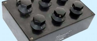
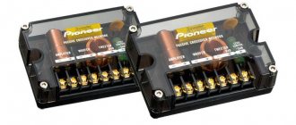
Passive speaker filters
Passive filters will be assembled with your own hands by anyone trained in soldering in a school physics course. As a last resort, enlist the help of Gonorovsky; there is no better description of the intricacies of the passage of signals through radio-electronic lines that have nonlinear properties. The presented material interested the authors in low and high frequency filters. Those wishing to divide the signal into three parts should read works that reveal the basis of bandpass filters. The maximum permissible (or breakdown) voltage will be scanty, the nominal value will become significant. Matching the mentioned electrolytic capacitors are capacitances with a nominal value of tens of microfarads (three orders of magnitude higher than those used by an active filter).
Beginners are concerned about the issue of obtaining a voltage of +15, -15 V to power speaker systems. Wind a transformer (an example was given, PC program Trans50Hz), equip it with a full-wave rectifier (diode bridge), filter, enjoy. Finally, buy an active or passive filter. This thing is called a crossover, carefully select the speakers, correlate the ranges more accurately with the filter parameters.
For passive crossovers of speaker systems, you will find many calculators on the Internet (https://ccs.exl.info/calc_cr.html). The calculation program takes the input impedances of the speakers and the division frequency as the initial numbers. Enter the data, the robot program will quickly provide the values of capacitances and inductances. On the page below, specify the filter type (Bessel, Butterworth, Linkwitz-Riley). In our opinion, this is a task for the pros. The above active stage is formed by 2nd order Butterworth filters (rate of frequency response reduction 12 dB per octave). It concerns the frequency response (frequency response) of the system, understandable only to professionals. When in doubt, choose the middle ground. Literally check the third circle (Bessel).
▍ Piecewise continuous filters
Based on the initially posed problem, it is more convenient to describe the frequency response with a piecewise continuous function, in which the passbands and suppressions are constant and equal to 1 and 0, respectively, specified on a logarithmic scale. A separate article was devoted to the derivation of such functions; here, as an example, we take the standard smooth-step function constructed from a cubic polynomial of the 3rd order: From its graph on a linear scale, the symmetry that ensures summation to unity is clearly visible:
But on a logarithmic scale - no longer, but the main difference from the Linkwitz-Reilly filter is clearly visible - the decline is not flat, but has a pronounced border on the right, beyond which the volume (in decibels) is equal to minus infinity. Adding to one gives a high-pass filter (yellow), which has the desired symmetry:
At a larger volume range, this property of filters looks even more obvious:
Unlike classical filters, where the parameterization of the slope of the frequency response through an order of magnitude is determined by their circuit implementation, here we can operate directly with the width of the coupling band, setting it in octaves from the crossover frequency of -6 dB.
This will require an additional function to convert the logarithmic scale to linear, the value of which will be passed to the smooth-step function to determine the amplitude at frequency . It can be determined in several ways: 1) through cutoff frequencies
2) through central frequency and width (in octaves)
3) through the central and upper limit frequency
4) through the central and lower limit frequency
Now, using a certain filter function, you can obtain its impulse response using the algorithm described above, which can be defined as a separate function:
SymmetricFilterImpulseResponse[f0_, width_, size_, samplerate_, ClipFunction_, WindowFunction_] := Table[ClipFunction[(2 Log[(index samplerate)/(f0 size)])/ (width Log[2]) ] (-1)^index , {index, 0, size/2}] // Join[#, Reverse[#[[2 ;; size/2]]]] & // InverseFourier[#] Table[WindowFunction[(index-1)/size-1/2], {index, 1, size}] & // #/ Fourier[#, FourierParameters - > {1, -1}][[1]] & // Re
Note
In different implementations of convolution via DFT, there are different approaches to normalizing the impulse response by amplitude.
Here it is not done as a separate operation, but by setting the FourierParameters option when performing DFT. Passing our cubic filter and Nuttall window to this function we get
SymmetricFilterImpulseResponse[1000, 0.5, 512, 48000, FilterCubicClip, NuttallWindow] ↓
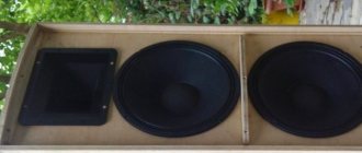
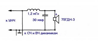
Subwoofer Filter
A low-pass filter made of an inductor and a large capacitor is called a second-order Butterworth circuit. It provides a roll-off of frequencies above the cutoff frequency of up to 12 dB per octave. The scheme works as follows. The inductance in the LC circuit acts as a variable resistor. Its resistance is directly proportional to frequency and increases with increasing range. Therefore, high frequencies practically do not reach the woofer. A capacitor also performs the same function. Its resistance is inversely proportional to the frequency and it is connected in parallel with the loudspeaker.
Since the device circuit must pass low frequencies well and cut off high frequencies, the capacitors of such a device have a large capacity. A passive filter for a speaker can be made using a more complex circuit. If you connect two Butterworth circuits in series, you get a fourth-order device consisting of two inductors and two capacitors. It provides a low-frequency loudspeaker roll-off of 24 decibels per octave.
In order to equalize the frequency response and more accurately match the Butterworth circuit and the speaker, a resistor with a small resistance is connected between the inductor and the capacitor. For this purpose it is better to use wirewound resistors.
▍ Several interesting filter functions
In addition to the cubic one already discussed, you can come up with many other functions for filters based on some mathematical idea.
It also matters how easily (if at all) the inverse function can be calculated. Parabolic, least computationally expensive. If necessary, the inverse function can be found quite simply:
Cubic. The inverse function to it is already a little counterintuitive (and if you are wondering where the trigonometric functions come from here, then here):
Using a 5th degree polynomial, with two zero derivatives at the interface boundaries. The inverse function here is not expressed in elementary functions (and therefore is not given):
Using a 13th degree polynomial - with additional “straightening”:
Using a rational polynomial gives a smoother characteristic and a simpler inverse function than the cubic one:
With a given number of zero derivatives at joining points, a special case of which is the previous function. Its inverse function is also easy to find:
Linearly decreasing on a logarithmic scale:
A smoother version of the previous one with the ability to adjust the “hardness”. Here the inverse function for arbitrary n is not expressed in elementary functions:
With an infinite number of zero derivatives at the joining points, which ensures perfect conjugation. And here the inverse function is easy to find:
With the fastest decaying impulse response - which, with sufficiently large (), allows you to do without a window function at all. The formula itself is obtained by modulating the argument of the cubic function, i.e. :
Here is a special function (error function), defined as an integral of the Gaussian. Instead, you can use the hyperbolic tangent function - the impulse response will also decay quite quickly, although not as quickly as in the previous case. Moreover, for large n, it will visually resemble Linkwitz-Reilly, and this is not at all accidental -
because
Having made a replacement in the function and reduced it, we get nothing more than