An alternative to humming bass reflexes: transmission lines (TQWT, ALT)
Today, the most popular acoustic design for both home and studio speakers is deservedly considered bass reflex. Using a bass reflex is a simple and inexpensive way to get enough low frequencies without using a large radiating surface area of speakers and cabinet-like enclosures. However, like other rational solutions in electroacoustics, the use of bass reflexes has disadvantages. And the shortcomings have a critical impact on the fidelity of reproduction. Among the most harmful disadvantages of these speakers are muttering, turbulent humming, resonant rattling, hooting and other “malignant” features of FI sound.
I want to get rid of all of the above. It’s difficult to find a music lover who hasn’t at least once criticized bass-reflex acoustics and looked for an alternative. With the latter, everything is not so simple. Among the possible options, labyrinth acoustics have become relatively widespread. The problem with labyrinths is that they are not technologically advanced and require high production standards, which naturally affects the cost. A relatively budget-friendly option for a labyrinth is a transmission line; it allows you to achieve a smooth frequency response while maintaining high sound pressure in the low-frequency range, but is less demanding in terms of calculations and production costs and is structurally simpler than classic labyrinth acoustics. Below the cut we talk about its history, features and modern use.
General information
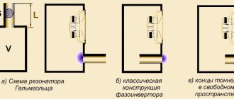
The transmission line is a hollow waveguide of variable or constant cross-section.
One end of the waveguide is closed, the other is open. The dynamic emitter is placed on the closed end side. The pipe is usually coiled and well damped. The point is to reduce the amplitude of oscillations of the dynamic radiator diffuser in the region of the lowest frequencies near the resonant frequency of the pipe and at the same time compensate for the decrease in the output from the speaker with the natural oscillations of the transmission line in the main, lowest-frequency mode. In the vast majority of cases, this can be achieved when the length of the translation line coincides with a quarter of the oscillation length at the natural resonance frequency of the speaker.
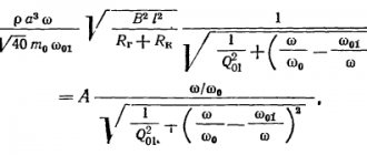
Gaponenko in his book “Do-It-Yourself Acoustic Systems” describes this with the following formula: Where L is the so-called.
“acoustic” length, which exceeds the actual geometric length of the line by the amount: where S is the cross-sectional area of the translation line.
In other words, it is necessary to tune the housing to a resonant frequency at which the air at the exit from the waveguide will move in phase with the oscillations of the diffuser. A properly designed transmission line is characterized by high precision in the low frequency range while maintaining sufficiently powerful, accentuated bass.
The bottom line is that it is easier to design a TL than other types of labyrinth design, and there will be no typical bass reflex problems. The characteristic humming and turbulent overtones are not typical for such acoustics. The main advantage of such speakers is the fidelity of reproduction in the low frequency range, while maintaining fairly small dimensions.
The “downside” of the translation line, as with structurally related labyrinths, is the criticality of correct calculation. Significant errors in calculations will significantly affect the sound, unnecessary rattling resonances will appear, or significant unevenness in the frequency response will appear. The good news here is that it is easier to calculate than more complex types of labyrinths.
Voight's well-forgotten trumpet
The earliest reference I can find to using a transmission line is Paul Voight's experience. The world chose to forget this pioneer of electroacoustics as the father of the electrodynamic emitter. In 1930, Voight developed, patented, and even put into limited production acoustic systems with a transmission line of the original design.
Paul Voigt
The fact is that at that time Voigt was developing speakers for cinemas, which traditionally for that time were designed as horns. Then he switched to radios and home speakers, where the wide-range dual-cone speaker with a mechanical crossover he used did not have a powerful low end. This necessitated the search for a new acoustic design more suitable for such speakers.
Having started development, he experimented and at a certain point decided to install the speaker in a not very traditional place, i.e. not at the beginning of the cone-shaped horn, but on one of its sides. In this design, the port is used to adjust the rear flow. The adjustment itself is carried out by increasing or decreasing the amount of damping material, depending on the type of driver used. The resonant frequency depends on the length of the waveguide as well as the position of the speaker.
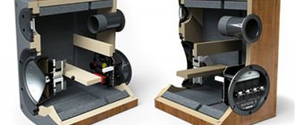
Modern version of TQWT
The transmission line, later called the Voight pipe, in cross-section is very similar to a classic horn, equipped with additional walls. Voight himself called the speaker TQWT (Tapered Quarter Wave Tube) - a conical quarter-wave tube. The case received this name for the reason that, as in all other classical types of TL, for the first mode a quarter of the wavelength fits in the pipe, for the second three quarters, for the third five, etc.
A relative disadvantage of this design is the inability to select a low cutoff frequency, since in this case you can get pronounced distortion in the low frequencies. The rest of the design makes it possible to create relatively compact floor-standing acoustics with “smooth” low frequencies, similar in characteristics to more complex labyrinths.
TQWT is practically not used in mass acoustics, but is very often used by radio amateurs when creating their own speakers. The problem is that there is not yet a full-fledged, developed theory describing the acoustic processes of TQWT systems, which cannot be said about well-described bass reflexes.
ATL - transmission line in shelves
When transmission lines are mentioned, we are usually talking about floor systems.
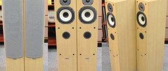
It is believed that the form factor and volume of bookshelf speakers require the most compact solutions, which is a bass reflex. However, there is a company that has found a comparatively effective design solution for the transmission line in shelf units. The founders and developers from PMC are fundamental opponents of FI acoustics and are convinced that the future lies with their innovation. PMC is one of the few modern companies that specialize in speakers with a transmission line. Over the decades of its existence, the company has developed dozens of models for studio and home speakers with a transmission line, some of which are still in existence today. Until the 2000s, they produced mainly floor-standing systems, since classic TL often assumed just such a form factor.
Later, engineers somewhat complicated the design and created the so-called. “latest generation transmission line” or ATL (Advanced Transmission Line). The peculiarity of this design is in the additional elements that make it possible to obtain the advantages of TL in bookshelf cabinets. The relative disadvantage of this design is that in terms of complexity and manufacturability, ATL is close to other labyrinth acoustics, which is guaranteed to increase the cost. The only good news is that one of the leaders of PMC, Peter Thomas, believes that:
“we truly believe that as prices go up, so does quality... our customers are not fools.” (from an interview with Sasha Metson in 2010).”
Summary and a few words in defense of FI
Despite the noticeable disadvantages of bass-reflex acoustics, the physics of its operation are well described, and most acoustic effects are predictable.
This certainly allows you to obtain a predictable result, which is very important in mass production. A number of companies have mastered broadcast lines, but it remains less technologically advanced and more expensive. It is possible that at some point transmission lines will become quite accessible and widespread, but this will not happen before the moment when the main processes occurring in the transmission line are theoretically described. If we talk about mass-produced and inexpensive (up to $500) speakers, it will be extremely difficult to find anything other than FI and speakers with a passive radiator.
Those who are tired of the problems of bass reflex speakers, but the aesthetics or dimensions of the premises do not allow the use of a closed box, should perhaps think about purchasing or creating their own transmission line. I would be grateful for any opinions regarding the broadcast line, especially people who have had the opportunity to create such speakers themselves are interested.
Traditional advertising We sell acoustic systems; our catalog includes both traditional acoustic with FI and speakers with other types of acoustic design, including with a broadcast line.
DIY speaker systems
Sound, music and loudspeaker What is sound? What is music? Let's clarify the terminology How does a dynamic head work? Dynamic head parameters What parameters affect the sound? Range of reproduced frequencies of the acoustic system Micro- and macrodynamics of sound reproduction Parameters and prices of speakers suitable for building good-sounding systems Acoustic systems
Types of Acoustic Design Why do small speakers sound different than large ones? Professional approaches Why do bass reflexes dominate the speaker market? Which “box” sounds better? Author's recommendations for making speaker systems
Calculation of closed boxes
What happens when you place a speaker in a closed box? Formula for calculating the frequency response of a closed box Optimal box volume Frequency response for a closed box of arbitrary volume When does a bass reflex become like a closed box?
Calculation of “transmission line” type systems
Acoustic modes in a pipe Martin King's experiment Basic principle of a transmission line Designs of speakers of the "T-line" type Calculation of T-line parameters Calculation of a T-line of variable cross-section Two heads in one acoustic system Types of transmission line Let's summarize
We create speaker systems with our own hands
Is it possible to make a good-sounding system at home? How to choose a speaker system design? Where can I get good speakers? What speaker parameters do you need to know to build an acoustic system? How to measure speaker parameters at home? Recommendations for selecting speakers in a multi-band system Crossover filters: introduction Approaching reality Author's recommendation: 1st order series filters Calculation and manufacture of inductors Tips for choosing capacitors Series and parallel filters in three-way systems High-order filters Housing manufacturing Let's summarize
DIY stereo system: transmission line
System with a single full-range speaker Correction of the frequency response of wide-range dynamic heads Two-way system with coaxial drivers Two-way system: separate low-frequency and high-frequency heads
DIY stereo system: three-way version
Where to begin? Selecting the main head System “10″+8″+1″” System “10″+6″+1″”
DIY triphonic system
Principle of operation Triphonic system with a common low-frequency emitter for two channels Transformation of a standard stereo complex into a triphonic system What is a “subwoofer”?
Tips for making your own amplifiers
The simplest option: an integrated circuit amplifier An improved option: a semiconductor amplifier without general feedback On the way to “tube sound”: simple hybrid amplifiers
List of symbols List of abbreviations List of references List of used Internet resources
Acoustic design of the speaker
Acoustic design of the speaker: let's start with the question of why it is needed. We all imagine old radios (radioli), where a single (broadband) dynamic head was installed in the front wall. They sounded, although they did not provide deep, velvety bass, and their speaker did not seem to have any special acoustic design (a special speaker housing). We will return to this issue below and see that in fact this is not the case.
Although if we take a dynamic head, connect it to an amplifier, position it in some arbitrary way, for example, hanging it on something, we will certainly hear sound. However, will we hear all the capabilities of this head? In the high-frequency range, perhaps, yes (if they are not limited by the recording itself and the entire amplification path). What is the problem with the sound of a completely open speaker for the low-frequency and mid-low frequency ranges?
The Acoustic Short Circuit Effect
To understand the problem with low-frequency reproduction by a speaker located in an open space, we need to introduce the concept of acoustic short circuit. What is the essence of this process? The driver cone (except for the tweeters) is open at both the front and rear. It is obvious that when it moves forward, it compresses the air in front and rarefies it in the back.
As a rule, low-frequency and mid-frequency dynamic drivers have a diameter somewhere from 10 to 30 cm. In such a situation, in their radiation range, air has the opportunity to flow around the edge of the speaker from one side to the other. What happens? It turns out that the front and rear parts of the diffuser sound in antiphase, and due to this flow, the sound pressure of the head is weakened. The lower the frequency of the emitted wave, the more it weakens.
The fact is that the effect of an acoustic short circuit depends on the wavelength of the emitted sound. At the lowest part of the audible range (tens of hertz) it is maximum. The sound wavelength in this case greatly exceeds the linear dimensions of the speaker. Thus, the sound wave goes around its edge and dampens vibrations on the opposite side.
Acoustic screen or shield
Acoustic screen or shield
The higher the sound frequency, the less this effect appears. And here we come to the first and simplest (from the point of view of the physics of the process) option. But it is, however, not so simple in terms of practical implementation. This option for acoustic design is an acoustic screen or shield. Indeed, in order to prevent an acoustic short circuit in the lowest frequency range, the size of such a screen must be commensurate with the wavelength at its lower boundary, and this is tens of meters. In practice, this is difficult to implement, and at home it is unrealistic.
However, the shield as an acoustic design is used in practice in elite acoustic systems of very high cost with expensive dynamic heads, usually of large diameter. Moreover, even with such heads, an acoustic short circuit cannot be ruled out when using a shield, and at the very bottom there will be a weakening of the bass. However, since the speaker cone operates in free space, such a speaker system has a minimum of distortion. True, another problem awaits us here - distortion from the walls.
Therefore, the shield cannot be installed in close proximity to the walls, and the walls themselves must be equipped with sound-absorbing panels. In short, no matter how much you love perfect sound, if you live in a small apartment and do not have the opportunity to equip your room for listening to music, this solution will not suit you.
Open box
Open box
Now let's think about how we can improve the acoustic screen without changing its essence. This solution is obvious. After all, if you bend the side walls of the shield, you can increase the path of the sound wave to achieve acoustic closure without increasing its front dimensions. Now you get a box with side walls, but without a back. The speaker continues to play in open space, but now, all other things being equal, the dimensions of the acoustic design have decreased.
True, there may be reflections from the side walls, but these walls can be damped (that is, covered with sound-absorbing material). If the box is very deep (however, in practice they are not used), a pipe near the box can become a resonator. But this is an unrealistic case and a completely different acoustic design. However, in the midrange, poor box proportions can degrade its sound. Therefore, such acoustics are usually not made deep, while the side walls make it possible to reduce (compared to the shield) the dimensions of its front wall by 25-40%, which is already good.
And in the case of an open box, we are faced with the same problems with the acoustics of the room in which it is installed - reflections from the walls. The next development of the same open box is due to the fact that its low-frequency component can be somewhat improved by partially complicating the movement of the sound wave through the back wall, closing it with a light panel with a large number of holes, which nevertheless limit, to some extent, the passage of the sound wave ( acoustic resistance panel).
If the area of these holes is insufficient, problems will arise with attack (sound dynamics) at low frequencies, so the optimal open/closed ratio of the box is selected by ear. Now let's go back to the beginning of the article and remember where we saw similar acoustic resistance panels. Well, of course, these are old tube receivers and radios, speakers of some electrophones! Here it is, new - well forgotten old! However, the level of low frequencies that satisfied most users in the 50-60s of the last century, in the 70s no longer satisfied many.
Closed box
Closed box
Further, reasoning logically, we now ask ourselves the question: if partially closing the rear wall increased the low-frequency response of the speaker system, maybe it should be closed completely?
Yes, it turned out to be possible to do this, but the properties of the dynamic head, which will work with a closed box, should be different in comparison with the emitters of our tube radios. Here, first of all, it is worth mentioning the so-called quality factor of the speaker (we will talk more about the characteristics of dynamic heads separately) and the minimum lower frequency that it is capable of playing. For now, in a nutshell: quality factor is the sharpness of the resonance of the oscillatory system (and the diffuser on its suspensions, of course, is an oscillatory system).
Without going into details now, let's say that a hermetically sealed acoustic system increases both the quality factor of the head embedded in it and the resonance frequency of the entire system, and therefore increases the lower frequency that the latter can reproduce.
On the other hand, a closed box (if it is rigid enough) eliminates rear radiation from the speaker and eliminates (at the speaker level) an acoustic short circuit. However, with the small width of our acoustics, it can arise at the level of the system as a whole. But this is a separate conversation. And we can now worry much less about the fact that there is a wall behind our speakers.
In this case, of course, the volume of closed acoustics will be reduced due to the fact that the rear radiation is isolated, and various resonance phenomena can occur inside it (which is also worth discussing separately). Here we will only say that to reduce the latter, the internal walls of a closed box, and in some cases its entire space, are damped with sound-absorbing materials.
Such acoustic systems were quite popular in the 70s and early 80s of the last century. Now the market is almost completely filled, with the exception, perhaps, of the very elite segment, with acoustic design such as a bass reflex. What kind of acoustic design is this, and why is it so popular?
Bass reflex
Bass reflex
Let's move further in our reasoning and ask the question: is it possible to use the radiation from the rear side of the speaker, which is lost in a closed box due to its closedness, but not return to completely open solutions? Yes, at least two options are visible here. We have already touched on the first one: turning the box into a long pipe (but more on that below). The second solution is to build a smaller resonator into a closed box. This is the bass reflex design that has flooded the market.
How it works? The frequency of the additional resonator (it can be either a tube or a slot in the system body) is selected somewhat lower than the frequency that our low-frequency head can effectively play. Thus, it turns out that up to a certain frequency the speaker plays, and below, due to the resonance of the bass reflex (port), the sound mainly comes through the latter. At the same time, the phases of the signal “walk” depending on its frequency, and calculating all the subtleties of the sound of such a system is not easy (although there are formulas and ready-made software solutions).
As a result, we get a kind of compromise solution, which has (especially with some miscalculations) a number of problems (for example, the sounds of air moving through the port). With all this, this solution allows you to expand the sound range of the low-frequency dynamic head with a relatively small size of the system body. Remember that a closed box raises the speaker's threshold?
This, in turn, makes it possible to make mass-produced models of speaker systems at lower costs, using more budget speakers. For most casual listeners this is acceptable. However, in fairness, it is worth saying that with accurate calculation, a bass reflex system with good heads and a fairly thick-walled body can sound at a high level (especially systems with two ports). And we see that there are quite expensive and at the same time good (which does not always correlate) bass reflex systems.
Passive radiator
Passive radiator
Now about another option for an additional resonator in speaker systems. What if the column of air enclosed in the port is replaced with a membrane that will also operate at its resonance just below the main speaker?
Yes, that's possible. This solution is usually called a passive radiator, passive speaker, passive radiator. Although “radiator” sounds somehow inappropriate here.
What would be the pros and cons of such a solution? Since we replaced the air with a diffuser (by the way, usually for this purpose they take a speaker basket with a diffuser, a suspension, but without a coil and a magnet), then by definition there cannot be any overtones from the movement of air through the port.
This is good, what's bad? The bad thing is that our passive radiator weighs significantly more than air. With a low self-resonance, its weight will reduce the dynamics at low frequencies. In addition, an unfinished speaker costs more than the port tube (although this is a separate and controversial issue). A passive radiator requires fine tuning.
As a result, such a solution is used, as a rule, in two absolutely polar segments: in very cheap compact portable systems - boomboxes, which have a fairly distant relationship with music, and in elite subwoofers.
Transmission line, or acoustic labyrinth
Transmission line, or acoustic labyrinth
Now let's go back a little (to the open box) and try to make it so deep that it turns into a pipe that has its own resonance in the low frequency region. Now it turns out that we don’t need a bass reflex. The resonance of the speaker body can itself be adjusted so that it expands the sound of the speaker downward, and, unlike a bass reflex, it will do this more softly, with a lower quality factor.
The fact is that the bass reflex, although it expands the range of the dynamic head downward, but the decline in its resonance turns out to be steeper, which is also not very well perceived by ear. The solution we are considering - the transmission line - gives a smoother and more natural decline. A lot can be said about transmission lines (they require not even one article, but a whole series). In this review publication, I consider it necessary, mainly, to identify topics for more detailed discussions.
Therefore, without delving into the types of transmission lines, let’s briefly go over their general pros and cons. So, a transmission line, as a rule, is not a compact solution, although if you fold it many times (accordion-style), you can make shelf options. A large number of bends, at the same time, adds additional parasitic resonances (and this is the main problem of such acoustic design).
There are a huge variety of transmission line designs. Our diagram shows a variant in which the dynamic head is located not at the end of the line, but 1/3 from its beginning (this is done in most designs). This technique allows you to significantly weaken the second (most significant) harmonic of the line.
You have to fight the rest (weaker ones), as always, by filling the transmission line with sound-absorbing materials. And if you overdo it with damping, then, as usual, you will get a decrease in attack and a more sluggish sound. So again, as with any of the acoustic design options we've discussed today, it's an art of compromise. And this once again confirms that there are no ideal solutions in the world, and any high-quality product is the best combination of compromises.
Recommended reading:
Nonlinear distortions in tube and transistor low-frequency amplifiers
Piston and wave modes of speaker operation. Broadband and narrowband emitters
Dynamic head as a sound source
How many bands should there be in a speaker system?
A simple method for setting up a bass reflex
I started doing “column construction” in the early 80s. And if at first it was just a “speaker in a box,” then, naturally, the study of the influence of the parameters of the box (and bass reflex) on the sound of the speaker began.
There are many "subwoofer builders" out there, but for the vast majority it is simply a "speaker in a box" and the bigger the better. Yes, to some extent, this is correct for a closed box. But for a bass reflex...
The bass reflex requires careful adjustment. What do we see in practice? As a bass reflex, people install sewer pipes of arbitrary length, make “slotted bass reflexes” in the image: “Vasya made them according to these dimensions,” while installing another speaker. Anyone who imagines this is limited to making a closed box (and rightly so!).
Of course, there are great modeling programs, such as JBL SpeakerShop. But they all require the introduction of a bunch of initial parameters. And even knowing them, the discrepancy with practice is usually huge
(the speaker turned out to be slightly different, the box is slightly different in size, we don’t know what filler and how much, the bass reflex pipe is slightly different, we don’t know the acoustic resistance, etc.)
There is a simple technique for setting up a bass reflex, which does not require knowing the exact source data of the speakers, boxes, and also does not require complex measuring instruments or mathematical calculations. Everything has already been thought out and tested in practice!
I want to talk about a simple method for setting up a bass reflex, which gives an error of no more than 5%. A technique that has existed for more than 30 years. I used it when I was a schoolboy.
How does a box with a bass reflex differ from a closed box?
Any speaker, like a mechanical system, has its own resonant frequency. Above this frequency the speaker sounds “pretty smooth”, and below this frequency the level of sound pressure it creates drops. Drops at a rate of 12 dB per octave (i.e., 4 times per twofold decrease in frequency). The “lower limit of reproducible frequencies” is considered to be the frequency at which the level drops by 6 dB (i.e., 2 times).
Frequency response of dynamics in open space
- Sign in OK
By installing the speaker in a box, its resonant frequency will increase slightly due to the fact that the elasticity of the air compressed in the box will be added to the elasticity of the diffuser suspension. A rise in the resonant frequency will inevitably “pull with it” the lower limit of the reproduced frequencies. The smaller the volume of air in the box, the higher its elasticity, and, consequently, the higher the resonant frequency. Hence the desire to “make the box bigger.”
Yellow line – frequency response of the speaker in a closed box
It is possible to make the box “larger” to some extent without increasing its physical dimensions. To do this, the box is filled with absorbent material. We will not go into the physics of this process, but as the amount of filler increases, the resonant frequency of the speaker in the box decreases (the “equivalent volume” of the box increases). If there is too much filler, the resonant frequency begins to rise again.
Let us omit the influence of box size on other parameters, such as quality factor. Let's leave this to experienced "column builders". In most practical cases, due to limited space, the volume of the box is quite close to optimal (we are not building cabinet-sized speakers). And the point of the article is not to burden you with complex formulas and calculations.
We got distracted. With a closed box everything is clear, but what does a bass reflex give us? A bass reflex is a “pipe” (not necessarily round, maybe rectangular in cross-section and a narrow slot) of a certain length, which, together with the volume of air in the box, has its own resonance. At this “second resonance” the sound output of the speaker rises. The resonance frequency is chosen slightly lower than the resonance frequency of the speaker in the box, i.e. in the area where the speaker begins to decline in sound pressure. Consequently, where the speaker experiences a decline, a rise appears, which to some extent compensates for this decline, expanding the lower limit frequency of the reproduced frequencies.
Red line – frequency response of the speaker in a closed box with a bass reflex
It is worth noting that below the bass reflex resonance frequency the sound pressure drop will be steeper than that of a closed box and will be 24 dB per octave.
- Diagnostics and tuning of car audio systems
Thus, the bass reflex allows you to expand the range of reproduced frequencies towards lower frequencies. So how to choose the bass reflex resonance frequency?
If the bass reflex resonance frequency is higher than optimal, i.e. it will be close to the resonant frequency of the speaker in the box, then we will get “overcompensation” in the form of a protruding hump in the frequency response. The sound will be barrel-shaped. If the frequency is chosen too low, then the level rise will not be felt, because at low frequencies the speaker output drops too much (undercompensated).
Blue lines – not optimal bass reflex setting
This is a very delicate point - either the bass reflex will give an effect, or will not give any effect, or, on the contrary, will spoil the sound! The bass reflex frequency must be chosen very precisely! But where can you get this accuracy in a garage or home environment?
In fact, the proportionality coefficient between the resonance frequency of the speaker in the box and the resonance frequency of the bass reflex, in the vast majority of real designs, is 0.61 - 0.65, and if we take it equal to 0.63, then the error will be no more than 5%.
For anyone interested in reading the theory, I recommend:
1. Vinogradova E.L. “Design of loudspeakers with smoothed frequency characteristics”, Moscow, ed. Energy, 1978
2. “More about the calculation and manufacture of a loudspeaker,” g. Radio, 1984, No. 10
- How to set up a Mystery subwoofer
3. “Setting up bass reflexes”, g. Radio, 1986, No. 8
Now let’s transfer theory to practice - it’s closer to us.
How to measure the resonant frequency of a box speaker? As is known, at the resonant frequency, the “modulus of total electrical resistance” (Impedance) of the voice coil increases. Roughly speaking, resistance is growing. If for direct current it is, for example, 4 Ohms, then at the resonant frequency it will increase Ohms to 20 - 60. How to measure this?
To do this, you need to connect a resistor in series with the speaker with a value an order of magnitude higher than the speaker’s own resistance. A resistor with a nominal value of 100 - 1000 Ohms is suitable for us. By measuring the voltage across this resistor, we can estimate the "impedance modulus" of the speaker's voice coil. At frequencies where the speaker impedance is high, the voltage across the resistor will be minimal, and vice versa. So, how to measure it?
Measuring speaker impedance
The absolute values are not important to us, we just need to find the maximum resistance (minimum voltage across the resistor), the frequencies are quite low, so you can use a regular tester (multimeter) in AC voltage measurement mode. Where to get the source of sound frequencies?
Of course, it’s better to use an audio frequency generator as a source... But let’s leave that to the professionals. “Nobody forbids us” to create a CD with a recorded range of audio frequencies, created in some computer program, for example, CoolEdit or Adobe Audition. Even I, having measuring instruments at home, created a CD of 99 tracks, a few seconds each, with a range of frequencies from 21 to 119 Hz, in 1 Hz steps. Very comfortably! I put it in the radio, you jump through the tracks and change the frequency. The frequency is equal to the track number + 20. Very simple!
The process of measuring the resonant frequency of a speaker in a box is as follows: we “plug” the bass reflex hole (a piece of plywood and plasticine), turn on the CD to play, set an acceptable volume, and, without changing it, “jump” along the tracks and find a track on which the voltage is at resistor is minimal. That's it - we know the frequency.
By the way, in parallel, by measuring the resonant frequency of the speaker in the box, we can select the optimal amount of filler for the box! Gradually adding the amount of filler, we look at the change in the resonant frequency. We find the optimal quantity at which the resonant frequency is minimal.
Knowing the value of the “resonant frequency of the speaker in a box with filler” it is easy to find the optimal resonant frequency of the bass reflex. Just multiply it by 0.63. For example, we obtained the resonant frequency of the speaker in the box as 62 Hz - therefore, the optimal resonance frequency of the bass reflex will be about 39 Hz.
Now we “open” the bass reflex hole, and by changing the length of the pipe (tunnel) or its cross-section, we tune the bass reflex to the required frequency. How to do it?
Yes, using the same resistor, tester and CD! You just need to remember that at the resonance frequency of the bass reflex, on the contrary, the “modulus of total electrical resistance” of the speaker coil drops to a minimum. Therefore, we need to look not for the minimum voltage across the resistor, but, on the contrary, for the maximum - the first maximum, located below the resonance frequency of the speaker in the box.
Naturally, the bass reflex tuning frequency will differ from the required one. And believe me - very much... Usually, towards low frequencies (undercompensation). To increase the bass reflex tuning frequency, it is necessary to shorten the tunnel or reduce its cross-sectional area. This needs to be done gradually, half a centimeter at a time...
This is what the speaker impedance module in a box with an optimally tuned bass reflex will look like in the low-frequency region:
That's the whole technique. Very simple, and at the same time, giving a fairly accurate result.
Author: Andrey Golubev
, Moscow
Content:
Introduction
When calculating the port, you need to choose your preferred music genre. If you are rock fans, then a low port setting will not suit you, and vice versa, when listening to blacks, a high port setting will not suit you.
For beginners, it is better to choose something universal and preferably on a pipe, since the slot box cannot be simply remade to change the setting.
Music genres:
- Low setting
- frequency 25 - 29 Hz. For fans of flex, the car shakes, the windshield blows up and the most important thing is the wind, a lot of wind. The bass with this setting is deep and soft, which does not hurt the ears. — With this setting, the subwoofer will not play strawberry, electro, rock and pop music. — Not all subwoofers are capable of reproducing such frequencies normally. - Everyday setting
is frequency 30 - 35 Hz. The most common and popular port setting. For fans of blacks and dub step, where there is body flex. The bass with this setting is more pressing to the ear. - Musical setting
- frequency 36 - 40 (42) Hz.
Universal setting or, more correctly, BALANCE
between all genres. The bass with this setting is more pronounced, fast but hard. Flex, accordingly, is minimal. — Short-throw subwoofers are more suitable. — Option aside sound quality. - Sport setting
- frequency above 45 - 55 Hz.
This setting is used for sound pressure measurements at competitions. People call such a box a COMBAT box
. The bass with this setting is very hard and it is impossible to listen to music. — We do not recommend using this setting for everyday listening.
How to determine the bass reflex tuning frequency?
- The easiest way to check the bass reflex tuning frequency is using the Frequency Tone Generator. At the box tuning frequency, the speaker cone stroke is minimal. We start the tone generator, set the approximate frequency and, in 1 Hz steps, determine at what frequency the stroke is minimal.
- The second method is no less simple, similar to the first. It is necessary to place the subwoofer with the diffuser up and pour cereal or something small and light onto it. We start the tone generator, set the approximate frequency and, in 1 Hz steps, determine at what frequency the material remained motionless, and at frequencies higher or lower it jumped noticeably. This frequency will be the bass reflex tuning frequency.
Recommendations
We advise you to choose the acoustic design of the box, specifically on the pipe, if you need precise tuning, or to get the desired result from measurements.
If you don’t like the port setting, you can simply change it to a longer one or cut off the pipe.
- The shorter the pipe, the higher the setting;
- The longer the pipe, the lower the setting.
Don’t forget, there is no exact port tuning frequency by calculation; plus or minus 2 Hz deviation is the norm.
Today, the most popular acoustic design for both home and studio speakers is deservedly considered bass reflex. Using a bass reflex is a simple and inexpensive way to get enough low frequencies without using a large radiating surface area of speakers and cabinet-like enclosures. However, like other rational solutions in electroacoustics, the use of bass reflexes has disadvantages. And the shortcomings have a critical impact on the fidelity of reproduction. Among the most harmful disadvantages of these speakers are muttering, turbulent humming, resonant rattling, hooting and other “malignant” features of FI sound.
I want to get rid of all of the above. It’s difficult to find a music lover who hasn’t at least once criticized bass-reflex acoustics and looked for an alternative. With the latter, everything is not so simple. Among the possible options, labyrinth acoustics have become relatively widespread. The problem with labyrinths is that they are not technologically advanced and require high production standards, which naturally affects the cost. A relatively budget-friendly option for a labyrinth is a transmission line; it allows you to achieve a smooth frequency response while maintaining high sound pressure in the low-frequency range, but is less demanding in terms of calculations and production costs and is structurally simpler than classic labyrinth acoustics. Below the cut we talk about its history, features and modern use.
General information
The transmission line is a hollow waveguide of variable or constant cross-section.
One end of the waveguide is closed, the other is open. The dynamic emitter is placed on the closed end side. The pipe is usually coiled and well damped. The point is to reduce the amplitude of oscillations of the dynamic radiator diffuser in the region of the lowest frequencies near the resonant frequency of the pipe and at the same time compensate for the decrease in the output from the speaker with the natural oscillations of the transmission line in the main, lowest-frequency mode. In the vast majority of cases, this can be achieved when the length of the translation line coincides with a quarter of the oscillation length at the natural resonance frequency of the speaker. Gaponenko in his book “Do-It-Yourself Acoustic Systems” describes this with the following formula: Where L is the so-called. “acoustic” length, which exceeds the actual geometric length of the line by the amount: where S is the cross-sectional area of the translation line.
In other words, it is necessary to tune the housing to a resonant frequency at which the air at the exit from the waveguide will move in phase with the oscillations of the diffuser. A properly designed transmission line is characterized by high precision in the low frequency range while maintaining sufficiently powerful, accentuated bass. The bottom line is that it is easier to design a TL than other types of labyrinth design, and there will be no typical bass reflex problems. The characteristic humming and turbulent overtones are not typical for such acoustics. The main advantage of such speakers is the fidelity of reproduction in the low frequency range, while maintaining fairly small dimensions. The “downside” of the translation line, as with structurally related labyrinths, is the criticality of correct calculation. Significant errors in calculations will significantly affect the sound, unnecessary rattling resonances will appear, or significant unevenness in the frequency response will appear. The good news here is that it is easier to calculate than more complex types of labyrinths.
Voight's well-forgotten trumpet
The earliest reference I can find to using a transmission line is Paul Voight's experience. The world chose to forget this pioneer of electroacoustics as the father of the electrodynamic emitter. In 1930, Voight developed, patented, and even put into limited production acoustic systems with a transmission line of the original design.
Paul Voigt
The fact is that at that time Voigt was developing speakers for cinemas, which traditionally for that time were designed as horns. Then he switched to radios and home speakers, where the wide-range dual-cone speaker with a mechanical crossover he used did not have a powerful low end. This necessitated the search for a new acoustic design more suitable for such speakers. Having started development, he experimented and at a certain point decided to install the speaker in a not very traditional place, i.e. not at the beginning of the cone-shaped horn, but on one of its sides. In this design, the port is used to adjust the rear flow. The adjustment itself is carried out by increasing or decreasing the amount of damping material, depending on the type of driver used. The resonant frequency depends on the length of the waveguide as well as the position of the speaker.
Modern version of TQWT
The transmission line, later called the Voight pipe, in cross-section is very similar to a classic horn, equipped with additional walls. Voight himself called the speaker TQWT (Tapered Quarter Wave Tube) - a conical quarter-wave tube. The case received this name for the reason that, as in all other classical types of TL, for the first mode a quarter of the wavelength fits in the pipe, for the second three quarters, for the third five, etc.
A relative disadvantage of this design is the inability to select a low cutoff frequency, since in this case it is possible to obtain an expression of distortion at the low frequencies. The rest of the design makes it possible to create relatively compact floor-standing acoustics with “smooth” low frequencies, similar in characteristics to more complex labyrinths. TQWT is practically not used in mass acoustics, but is very often used by radio amateurs when creating their own speakers. The problem is that there is not yet a full-fledged, developed theory describing the acoustic processes of TQWT systems, which cannot be said about well-described bass reflexes.
ATL - transmission line in shelves
When transmission lines are mentioned, we are usually talking about floor systems. It is believed that the form factor and volume of bookshelf speakers require the most compact solutions, which is a bass reflex. However, there is a company that has found a comparatively effective design solution for the transmission line in shelf units. The founders and developers from PMC are fundamental opponents of FI acoustics and are convinced that the future lies with their innovation. PMC is one of the few modern companies that specialize in speakers with a transmission line. Over the decades of its existence, the company has developed dozens of models for studio and home speakers with a transmission line, some of which are still in existence today. Until the 2000s, they produced mainly floor-standing systems, since classic TL often assumed just such a form factor.
Later, engineers somewhat complicated the design and created the so-called. “latest generation transmission line” or ATL (Advanced Transmission Line). The peculiarity of this design is in the additional elements that make it possible to obtain the advantages of TL in bookshelf cabinets. The relative disadvantage of this design is that in terms of complexity and manufacturability, ATL is close to other labyrinth acoustics, which is guaranteed to increase the cost. The only good news is that one of the leaders of PMC, Peter Thomas, believes that:
“we truly believe that as prices go up, so does quality... our customers are not fools.” (from an interview with Sasha Metson in 2010).”
Summary and a few words in defense of FI
Despite the noticeable disadvantages of bass-reflex acoustics, the physics of its operation are well described, and most acoustic effects are predictable. This certainly allows you to obtain a predictable result, which is very important in mass production. A number of companies have mastered broadcast lines, but it remains less technologically advanced and more expensive. It is possible that at some point transmission lines will become quite accessible and widespread, but this will not happen before the moment when the main processes occurring in the transmission line are theoretically described. If we talk about mass-produced and inexpensive (up to $500) speakers, it will be extremely difficult to find anything other than FI and speakers with a passive radiator. Those who are tired of the problems of bass reflex speakers, but the aesthetics or dimensions of the premises do not allow the use of a closed box, should perhaps think about purchasing or creating their own transmission line. I would be grateful for any opinions regarding the broadcast line, especially people who have had the opportunity to create such speakers themselves are interested. Traditional advertisingWe sell speaker systems; our catalog includes both traditional acoustics with FI, and speakers with other types of acoustic design, including a broadcast line.
Sources used:
- https://ldsound.ru/prostaya-metodika-nastrojki-fazoinvertora/
- https://worldsound.ru/blog/articles/chastota_nastroyki_fazoinvertora/
- https://habr.com/post/471408/