Calculation and adjustment of the bass reflex of the acoustic system
How to properly design a bass reflex? What should the bass reflex resonance frequency be? What should the length and diameter be? Online calculator for bass reflex tunnel sizes.A bass reflex (from an acoustics point of view) is a port (pipe, slot, etc.) in the speaker housing, which provides expansion of the reproduced low-frequency range due to the resonance of this port at a frequency lower than the resonant frequency of the speaker. The use of a bass reflex type makes it possible not only to expand the lower frequency range of a closed box, but also to increase the efficiency. The bass reflex tunnel can be made in various shapes and placed on any surface of the speaker. When developing an acoustic system, it is extremely important to correctly calculate the bass reflex box, since not only the range of reproduced frequencies, but also the quality of the entire sound as a whole depends on this.
Let's be indifferent to the variety of theoretical aspects that describe the physics of processes in this type of acoustics, and immediately answer the question: “Why, exactly?” This question may arise from an enthusiast who calculated the dimensions of the bass reflex according to the well-known formula from a smart book and became convinced of its inconsistency during an unsuccessful practical experience!
You won’t have to strain yourself too much, because Signor Jean-Piero Matarazzo (an authoritative specialist in the field of professional acoustics) has already helped us understand this pressing issue. This is what a respected Italian acoustician wrote in the article “Theory and Practice of a Bass Reflex”:
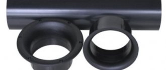
Fig. 1 Designs of bass reflexes with a tunnel in the form of a pipe
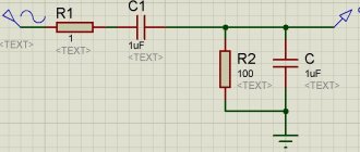
One of the most common wishes in the author’s e-mail is to provide a “magic formula” by which the ACS reader could calculate the bass reflex himself. This is, in principle, not difficult. A bass reflex is one of the cases of implementing a device called a “Helmholtz resonator” (Fig. 1 a). The tuning frequency of the Helmholtz resonator (or bass reflex, which is the same thing) can be calculated using the formula: where: Fb is the tuning frequency (Hz), s is the speed of sound (344 m/s), S is the cross-sectional area of the tunnel (sq. m) , L – tunnel length (m), V – box volume (cubic m), π = 3.14.
This formula is truly magical, in the sense that the bass reflex setting does not depend on the parameters of the speaker that will be installed in it. The volume of the box and the dimensions of the tunnel and the frequency of tuning are determined once and for all. Everything, it would seem, is done. Let's get started. Let us have a box with a volume of 50 liters. We want to turn it into a bass reflex enclosure with a 50Hz setting. They decided to make the diameter of the tunnel 8 cm. According to the formula just given, the tuning frequency of 50 Hz will be obtained if the length of the tunnel is 12.05 cm. We carefully make all the parts, assemble them into a structure, as in Fig. 1 b), and measure them to check the actual resulting resonant frequency of the bass reflex. And we see, to our surprise, that it is not equal to 50 Hz, as the formula would suggest, but 41 Hz. What's the matter and where did we go wrong? Nowhere. Our newly built bass reflex would be tuned to a frequency close to that obtained by the Helmholtz formula if it were made as shown in Fig. 1 c). This case is closest to the ideal model that the formula describes: here both ends of the tunnel “hang in the air,” relatively far from any obstacles. In our design, one of the ends of the tunnel approaches the wall of the box. For the air oscillating in the tunnel, this is not indifferent; due to the influence of the “flange” at the end of the tunnel, a virtual elongation occurs. The bass reflex will be configured as if the length of the tunnel was 18 cm, and not 12, as in reality.
It would seem that if the tunnel is completely placed outside the box, Fig.1.a) on the right, we get a Helmholtz resonator in its pure form. However, in practice, here too there is an empirical dependence of the “virtual lengthening” of the tunnel depending on its size. For a circular tunnel, one section of which is located far enough from the walls of the box (or other obstacles), and the other is in the plane of the wall, this elongation is approximately equal to 0.85D.
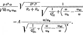
Now, if we substitute all the constants into the Helmholtz formula, introduce a correction for the “virtual elongation”, and express all dimensions in conventional units, the final formula for the length of a tunnel with a diameter D, ensuring the tuning of a box with a volume V to the frequency Fb, will look like this: Here the frequency Fb – in hertz, volume V – in liters, and length L and diameter D of the tunnel – in millimeters, as we are more familiar with.
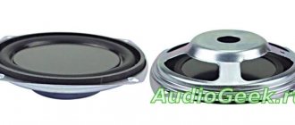
The geometric dimensions of the tunnel have their limitations. The great researcher of acoustic systems R. Small showed that the minimum cross-section of the tunnel depends on the diameter of the speaker, the maximum stroke of its diffuser and the tuning frequency of the bass reflex. Small proposed a completely empirical, but trouble-free formula for calculating the minimum tunnel size: Small derived his formula in his usual units, so that the speaker diameter Ds, the maximum cone stroke Xmax and the minimum tunnel diameter Dmin are expressed in inches. The bass reflex tuning frequency is, as usual, in hertz.
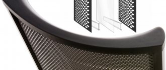
It often turns out that if you choose the right tunnel diameter, it turns out to be incredibly long. And if you reduce the diameter, there is a chance that the tunnel will “whistle” even at medium power. In addition to the jet noise itself, small-diameter tunnels also have a tendency to so-called “organ resonances,” the frequency of which is much higher than the bass reflex tuning frequency and which are excited in the tunnel by turbulence at high flow rates. When the calculated length of the tunnel turns out to be such that it almost fits in the housing and only a slight reduction in its length is required with the same setting and cross-sectional area, I recommend using a slotted tunnel of the same area instead of a round one, and placing it not in the middle of the front wall of the housing, as in Fig. .2 a), but close to one of the side walls, as in Fig. 2 b).
Fig.2 Designs of phase inverters with slot tunnels
Then at the end of the tunnel, located inside the box, the effect of “virtual lengthening” will be affected due to the wall located next to it. Experiments show that with a constant cross-sectional area and tuning frequency, the tunnel shown in Fig. 2 b) is approximately 15% shorter than with the design as in Fig. 2 a). A slotted bass reflex, in principle, is less prone to organ resonances than a round one, but to protect yourself even more, I recommend installing sound-absorbing elements inside the tunnel, in the form of narrow strips of felt, glued to the inner surface of the tunnel in the region of a third of its length.
Further reduction in the length of the tunnel can be achieved by using conical, exponential, and hourglass-shaped bass reflexes. Since such technologies are structurally complex and are not widely used in amateur radio practice, we will not consider them within the framework of this article. Better yet, let’s spice up the material covered with a couple of online counting rhymes that allow you to calculate tubular and slotted bass reflexes without unnecessary stress, a calculator and wooden abacus.
But first, let’s ask a reasonable question: what resonant frequency should the bass reflex be tuned to? The answer is very simple - at the optimal frequency. If the resonance frequency of the bass reflex is higher than optimal, i.e. it is close to the resonant frequency of the speaker in a closed box, then we will get a protruding hump on the frequency response, as a result of which the sound will be barrel-shaped. If the frequency is chosen too low, then the rise in the low-frequency level will not be felt, because at this frequency the speaker output will be too weak and there will be nothing to amplify. Thus, the resonance frequency of the bass reflex should be chosen slightly lower than the resonance frequency of the speaker in a closed box, i.e. in the area where the speaker experiences some drop in sound pressure. This decline is compensated by the rise of the bass reflex, which will ultimately lead to an expansion of the lower limit of reproduced frequencies.
In most real designs, the resonance frequency of the bass reflex is 0.61...0.65 of the resonance frequency of the speaker in a closed box .
And how easily and simply you can find out the resonance frequency of a loudspeaker in a closed box - we discussed in detail on this page. So:
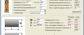
CALCULATOR FOR CALCULATING THE DIAMETER AND SECTIONAL AREA OF A BASE INVERTER TUNNEL
The diameter of the tunnel is a value that has practical meaning only for phase inverters with a round cross-section. The cross-sectional area characterizes both tubular and slot phase inverters.
Let's calculate the length of the bass reflex tunnel based on the volume of the box, the resonant frequency of the bass reflex and the diameter/sectional area of the tunnel:
CALCULATION OF THE LENGTH OF THE BASE INVERTER TUNNEL
The calculated length of the tunnel is correct for both cylindrical bass reflexes and slotted bass reflexes located at a considerable distance from the wall. If the slotted bass reflex is located close to one of the walls, as in Fig. 2 b), then its length should be shortened by 15%.
Design of Inter-M audio equipment systems
Design of audio equipment systems Inter-M
The Inter-M company is constantly improving and updating the range of professional equipment it produces. While maintaining high product quality, the company is actively introducing new circuit solutions and energy-saving technologies in the design of power amplifiers, and using new components in the production of speaker systems. Inter-M professional equipment models produced today meet the level of modern development of audio technologies and allow you to create a sound system of any complexity.
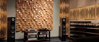
Acoustics Inter-M
A hall equipped with Inter-M acoustic systems.
One of the key components of a professional audio system and the starting point when building any high-quality sound cluster is the acoustic system. Properly selected and designed taking into account the acoustic characteristics of the sounded room, it will become a decisive factor in creating the necessary sound design for an event - be it a modest presentation of a new product or a large-scale conference, high-quality and atmospheric background accompaniment in a car showroom or a driving open-air concert performance.
The selection and design of a suitable professional sound system begins with an acoustic calculation of the object being sounded, which allows an objective assessment of the influence of architectural solutions. The goal of such calculations is ultimately to maximize the efficient use of acoustic systems.
By choosing the optimal power, correct placement of loudspeakers and direction of sound radiation, it is possible to compensate for the shortcomings of the acoustic design, for example, the “unfortunate” shape of the ceiling, which causes parasitic reflections of sound waves. And if when designing a background music broadcast system for a small hall you can do without complex calculations, then when building sound clusters using linear arrays such calculations are required. As a program that simplifies this task, you can use, for example, Ease Focus 2.0 software from AFMG.
Inter-M power amplifiers
Selecting Inter-M power amplifiers
After performing the calculations and selecting speaker systems, we move on to choosing power amplifiers manufactured by Inter-M. The article “Inter-M Power Amplifiers” will help you evaluate the capabilities of current models and highlight the fundamental advantages necessary for an individual design solution.To select the correct amplifier, including taking into account the characteristics of the speaker systems, it is important to follow the manufacturer's recommendations. Based on them, the article “Selection of Inter-M power amplifiers” was prepared. The professional amplifiers manufactured by Inter-M and referenced in our product information materials are rated to DIN POWER or EIAJ standards.
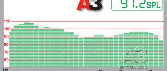
Relative power ratio of different standards
Relative ratio of audio signal powers of different standards
For professional amplifiers manufactured by Inter-M, the power output is usually specified at a given total harmonic distortion (THD) of 1% and a signal with a frequency of 1 kHz according to the EIAJ (or DIN POWER) standard. This characteristic is measured as the root mean squared power value of RMS (Root Mean Squared) - a standard measurement of the power of an audio amplifier or speaker system, at which the coefficient of harmonic nonlinear distortion is minimal and does not exceed the specified value. RMS power characterizes the average power at a constant active rated load. There are two commonly used designations for RMS power:
- IHF is the power delivered by the amplifier at 0.1% distortion;
- EIAJ/DIN POWER - the power produced by the amplifier at 1% distortion.
Conventionally, RMS (EIAJ/DIN POWER) can be considered equal to (1.5…2) • AES. The exact ratio is provided by the equipment manufacturer.
The figure shows the relative power ratio of different standards. The unit of power is the power of the audio signal in the AES standard. Relative to this value, the relationships for other standards are visible.
More detailed information about acoustic systems is presented in the material “Inter-M Acoustic Systems”, as well as in the articles “Selection and installation of Inter-M acoustic systems” and “Selection and installation of Inter-M line arrays”.
Transmission of an audio signal between equipment units of Inter-M professional audio systems
Transmission of an audio signal between equipment units of Inter-M professional audio systems
Most inter-unit connections and connections between units and sound sources are made using ready-made audio connecting cables. The transmission of an audio signal between units of equipment of professional audio systems is carried out according to a balanced circuit, where the signal is transmitted simultaneously along two conductors in antiphase relative to the common wire or screen. The use of such a scheme creates a high level of protection against interference, which is very important for ensuring high quality audio signal transmission. Accordingly, professional audio cables must consist of a two-core shielded cable with connectors at the ends having at least 3 contacts.
The connection between the output of the power amplifier and the speaker system is made using an speaker cable of acceptable cross-section and equipped with the necessary connectors. The cross-section of the conductors of the connecting audio cable is calculated taking into account the level of permissible power losses, depending on the length of the cable and the transmitted power.
Recommendations for selecting audio connecting cables and speaker cables are given in the article “Selecting speaker cables and audio cables.”
Examples of building distributed professional audio systems using optical technologies and IP networks are discussed in the article “Inter-M remote audio transmission equipment.”
Inter-M mixing consoles
Inter-M mixing consoles
Having determined the sound sources, we move on to choosing the number of required sound amplification channels. Each channel provides separate signal processing and amplification by one or more power amplifiers. The load of the amplifier (or amplifiers) will be one or more speaker systems.To select the necessary equipment for processing audio signals, use the overview article “Inter-M Equipment for Audio Processing”.