Maximum permissible forward current. Therefore, their housing is structurally designed to be mounted on a radiator.
The fourth position is important, since with increasing power the thermal output also increases.
To do this, it is enough to measure the resistance of each diode with a regular ohmmeter, focusing on the rectifier circuit and the bridge pinout. How to connect 2 ohm speakers and how to connect a car audio speaker cable with your own hands A diode only theoretically conducts current in one direction, and a dielectric in the other. To do this you will need to prepare: Four diodes with identical characteristics. They consist of four diodes connected to each other in a suitable manner.
But purchasing a good amplifier and subwoofer does not mean quality sound. In this case, the frequency of the output signal will double. Direct voltage. For example, a popular bridge among radio amateurs that can withstand reverse voltages up to V is labeled as PSA. The diode bridge works on this principle.
How to connect an amplifier. Bridge connection #1
Connecting an amplifier with a bridge
Today we will look at such an interesting possibility of increasing power as connecting an amplifier with a bridge and how to connect 2 amplifiers in a similar way. In this mode, one channel works as a plus (+) and the other as a minus (-) , which increases the power by 2-2.5 times. The result will depend on the system power supply and amplifier model.
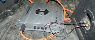
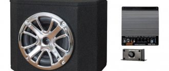
Most often, this operating mode is used for a subwoofer, as the most power-demanding element. You can connect either two amplifier channels or two separate monoblocks to the bridge.
Bridge connection of two channels
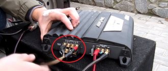
So, to bridge two channels of one amplifier, you need to take a plus (+) from one and a minus (-) from the other. For two and four channel amplifiers, the circuits are no different.
Bridge connection of 2 channels
Bridge connection of 4 channels
In principle, connecting an amplifier with a bridge is not a difficult operation; it does not require any jumpers or additional connections. Connect the positive wire from the subwoofer to the positive terminal (+) of one channel, and the negative wire, respectively, to the negative (-) terminal of the second.
Make sure your amplifier is bridged first.
The best car amplifiers
Are you looking for a high-quality and best car amplifier? This rating of car amplifiers is compiled on the basis of such parameters as: high demand with positive feedback from our customers, high-quality manufacturing - no manufacturing defects or service requests, as well as official warranty and post-warranty support in Ukraine.
Auto sound amplifier Blaupunkt GTA-270
Single-channel audio amplifier for cars Calcell VAC 1100.1
Single-channel audio amplifier Swat M-1.500
How to connect two amplifiers with a bridge
Master/Slave
Amplifiers designed for this connection have MASTER/SLAVE switches. Therefore, with a bridge connection, one of the amplifiers will be the master ( Master ) and the second will be the slave ( Slave ), set the switches in this accordance. It is to the Master that the interconnect cables (tulips) from the radio are connected, and from it, through a mono connector, the signal is transmitted to the Slave (with a single interconnect). This is done so that all settings and control are carried out from one monoblock - from the Master, that is, gain, filters, subsonic, etc. will be exhibited only there. There is no need to take Y splitters to try to plug interconnects into the Slave as well.
If the manufacturer declares that the amplifier can operate in a bridge, but there are no Master / Slave switches, then it will have two sockets with similar names - Bridge Input and Bridge Output . In this case, use the Bridge Output jack on the master amplifier and connect it to the Bridge Input jack of the slave amplifier.
Connecting speaker wires
Here, be careful and do not confuse anything: we connect the negative connectors of the two amplifiers to each other; then we connect the plus (+) of the Master to the plus of the subwoofer, and the plus of the Slave to the minus of the subwoofer !
Yes, there are two positive wires going to the subwoofer, no need to strain - everything is correct. The fact is that a direct signal is supplied to the input of one amplifier, and for the second the signal is turned 180 degrees. Therefore, at the output of one the positive potential increases, and at the output of the second it is the same but negative. The increase in power occurs because the amplifiers or channels (in the case of using one wuxia) operate at reduced resistance. For example, if the sub is connected to 4 ohms, then each amplifier or channel operates at 2 ohms, etc.
↑ UMZCH TDA7266, TDA7297 do not work from Krona!
Often there are complaints in the spirit of “it is indicated that the microcircuit runs on 6 Volts, but I connected a Krona battery with as much as 9 Volts, and the amplifier does not work, which means it sucks.” Do I need to comment? The crown doesn't work, you need a good power supply with sufficient current carrying capacity.
Today, a miniature UMZCH board is a common thing, but it won’t be possible to make a tiny ULF on it because you need a fairly powerful power supply and other wiring. And the power supply has dimensions much larger than the UMZCH board. There is no need to talk about a classic transformer power supply, especially since large power filter capacitors are needed.
With switching amplifiers, things are not so simple either. Cheap flyback power supplies can be a source of interference; it makes sense to move them outside the case, as in laptops. So, the power supply must be powerful enough and not cause interference.
Important points
- Make sure your amplifier supports bridged connections.
- Make sure your amplifier or amplifiers support the intended impedance.
- Keep in mind that when connecting two amplifiers to a bridge, the Slave's protection may be disabled. Watch him closely.
- Do not connect different channels/amplifiers separately to the coils.
A simple and clear video on how to connect two amplifiers to a bridge:
Happy connections!
Additional materials
There is a separate category of electronic devices - rectifier bridges. This is what a practical bridge rectifier circuit looks like. All that remains is to add a smoothing capacitor and see what happens. At the next stage, the situation is as follows: a positive charge accumulates in the first amplifier, and a negative charge accumulates in the second amplifier.
Instead of the classic pn junction, they use a metal-semiconductor contact.
The former are used in circuits with high-frequency electricity.
Parallel connection of coils - subwoofers.
For example, the power supply, which has already been discussed on the pages of the site, contains a single-phase full-bridge rectifier - a diode bridge. Share with your friends by clicking on the social button!
All necessary information, including capacitance, polarity and operating voltage can be seen directly on the capacitor. Combined connection. Front connection, part 1
Wiring
The wires are laid in such a way as to avoid damage and kinks. To do this, the wiring is placed in a flexible plastic tube of suitable diameter and laid under the floor covering.
To protect and shield speaker cables, they can be routed inside a split metal tube that can be grounded.
What do you need
To carry out the work yourself, you will need consumables and tools. A two-channel amplifier is installed when using:
- Cable with a cross-section of at least 2.5 mm2. The amplifier is often installed in the luggage compartment, so a long cable length will be required. It is not recommended to use low-quality material, because... It will not last for a long period and may cause interference.
- To protect the connections and the wire, insulating material is required: insulation, corrugated plastic tube.
- The quality of the connection can be improved by using special adapters. They allow, if necessary, to dismantle individual parts.
When working, a knife, a multimeter, a set of screwdrivers and some other tools are used. The amplifier is located in the luggage compartment. It is recommended to purchase or make a plastic container for it, which will protect the device from moisture and dirt.
Laying wires in the cabin
To connect a two-channel amplifier, you need to lay the cable around the cabin. In Supra and some types of cars, fastening is carried out using bolts and other elements. The main recommendations for carrying out such work are as follows:
Are you a car driver?! Then you can take this simple test and find out. Go to test »
- All finishing materials are first dismantled. If after disassembly it turns out that there is moisture under the trim, then you need to check the integrity of the body and protect it from water. High humidity can reduce system reliability.
- The interconnect cable is laid away from the power lines. Otherwise, there is a possibility of interference.
- In places where the cable comes into contact with the edges, it is recommended to use a corrugated tube. Minor vibration can cause the insulation to rub.
- To turn on the device, a separate power cable is laid. It is not recommended to connect directly to the battery, because there is a possibility of complete and rapid discharge.
- It is planned to install a safety element in close proximity to the power source.
The cable connection is made using soldering. It is recommended to clean the contacts first.
Amplifier power
The amplifier is installed in most cases in the trunk. This point complicates the installation of the cable from the power source. Among the features are the following:
- It is recommended to use a larger cable. It will be able to last for a long period of time.
- Provides for the presence of a key in the system.
- The power supply is routed away from the interconnect network. In this case, it is recommended to use the shortest path and also reduce the number of connections.
- A fuse is installed in the immediate vicinity of the power source. It is selected taking into account the power of the device; it is recommended to choose with a reserve.
When installing a fuse, it should be protected from environmental influences.
Grounding organization
The operating instructions for all amplifiers indicate that the device must be grounded. The recommendations are as follows:
- A cable with a thickness of at least 2.5 mm2 is used. Otherwise, there is a possibility that the core will overheat.
- For fastening, you can use any fastening element located in the immediate vicinity.
The wire must be protected from environmental influences.
↑ Printed circuit boards for TDA7297 and TDA7266SA
Today on Aliexpress you can buy both assembled modules based on these chips and kits for do-it-yourself soldering. They cost approx. 1 dollar, a stereo amplifier for that amount is not bad.
↑ UMZCH board with Ali
It’s quite a suitable option, but I don’t like everything about it, as I usually think that the boards I wired for my parts are better.
↑ My printed circuit boards
I didn’t like the drawings available on the Internet because the traces go behind the back of the microcircuits, the board will not allow you to screw the transistor to the radiator, the radiator will stand on the board. It will be impossible, for example, to screw the board to the amplifier body. I think it's better to solder the common wire jumper to the bottom of the board.
In the amplifier, you should not place ceramic capacitors in the sound path; film capacitors are needed. They take up more space on the board, although the distance between the pins is 5 mm like ceramics.
I also separated the power supply minus and the common input wire through resistor R3. This is not necessary, but then you need to make a board, exactly like in the datasheet. In boards from the Internet, the common wire is usually routed incorrectly. How critical this is is an open question, but in my boards, when powered by a stabilizer, the background is completely absent, and the noise from the high-frequency speaker is barely audible if you put your ear to it.
↑ About sound
Of course, they are inferior to audiophile amplifiers. But the sound is without obvious distortion and not annoying. All frequencies are reproduced, especially low ones. But the sound seems to be purified, simplified, smoothed out. There is no “air”, “liveness” and microdynamics.
But the disadvantages when listening to high-quality recordings turn into advantages when listening to MP3s and corresponding acoustics. The detail and transparency of higher-end amplifiers can only highlight the MP3's shortcomings.
I have my own “standards” for determining power (I was surprised to actually find confirmation on some datasheets), my own “musical” power, but it is fundamentally different from the bloated PMPO. For these amplifiers, my power rating is 1...2 W, and this is enough for home listening on acoustics with a sensitivity of about 90 dB.
↑ Measurements
So, the amplifiers are assembled and the power is connected. No adjustment is required, but you need to make sure that the constant voltage on all amplifier outputs is equal to half the supply.
I assembled several ULFs on the TDA7297 and TDA7266SA,
I powered them from a laboratory power supply, determined the maximum output signal using an oscilloscope at the limiting threshold, here are the tables with the results.
↑ Electrical characteristics of TDA7297 at 8.2 Ohm load
Here Usupply is the voltage of the power supply, Isupply. — current from the power supply according to its indicator. U load — load voltage. P load — load power. U amp. — amplitude of the output voltage (for comparison with the ideal graphs above). I ampl. — current taken from the output transistors.
So, with a 12 V supply, 6.3 W of undistorted power was obtained instead of the theoretical 9 W. 1.5 times less or 3 W less. Few? But compared to the “ideal” 2.25 W with a non-bridged output, it is almost 3 times more.
At 15 V the power is already 10 W. But what about the stated 15+15W DUAL BRIDGE promised in the datasheet? But this is advertising. Even on the datasheet graph, with a maximum power supply of 18 V, 14 W are received. The “electrical specifications” indicate that 18 V is the maximum permissible voltage. True, it is indicated elsewhere that the absolute maximum power supply is 20 V, I think that here 15 W will be received, but this is already “beyond the bounds”. And this is for genuine microcircuits.
Similar experiments on microcircuits with Ali will most likely end in profanity.
In general, the graph of the dependence of output power on supply voltage for my microcircuits coincides with that given in the datasheet. The information sheet states that the microcircuits have a bunch of protections against short circuits, overheating, and, among other things, there is a limit on the output current at 2 A, remember this and note that in the table above the maximum current is 1.59 A, i.e. it does not reach to the limit. I think the developers chose 2 A for a 16.5 V supply and an 8 ohm load.
↑ Electrical characteristics of TDA7297 at 4.1 Ohm load
The power was squeezed out more, but not twice, but by 30...40%. Why? At higher currents, losses in the microcircuit itself increase. I think you guessed that if the load is reduced to 2 ohms, then the losses will increase even more, but for these microcircuits I won’t even try.
It is also interesting that the current without restrictions was 2.5 A. Whether there is protection in the chip and how it works is unknown, and I don’t want to burn the chips on purpose. I feel sorry not for them, but for my time.
With a proprietary chip, we would get no more than 7.5 W due to current limitations. I think with a 16.5 V supply you can get about 15 W at 4 ohms, but the heating of the microcircuit will increase and a good heatsink will be required.
Why did I take measurements with an 11V supply? And this is battery powered - three Li-Ion cells. When fully charged, they will give 12 V, and when discharged to the standard 3.6...3.7 V, they will give just 11 V. You can estimate the maximum power from the “batteries”. More than 5 Watts into 8 ohms and about 9 Watts into 4 ohms from a small portable balalaika is not too bad. At the level of good portable radios of the past.
In my opinion, using these microcircuits with a power supply below 9 V is impractical, but with 3 or 4 18650 elements, it is quite possible. With a power supply of 12...16 V there will even be a power reserve.
↑ Graph of real modes
The “left” pair of transistors is the output of the first amplifier, the “right” pair is the output of the second. Pale gray transistors are closed, black ones are fully open. Drawings for points A and B of a sinusoid.
The current always flows only in one direction from the “+” supply to the “-” supply, but by cleverly controlling it, you can obtain an alternating voltage, and even with a full amplitude higher than the supply voltage. The voltage drop across transistors depends on the current, the element base, circuit design, etc. Here it is about 1 V. This is not much, but even this reduced the power from the ideal 9 W to the real 6.3 W.
Another note. Unfortunately, there is no normal internal diagram of the microcircuits; there is a slightly more detailed description of such a microcircuit.
I think that the virtual common wire (the audio input signal passes through it) is connected to the common wire at the input through capacitor C1 according to the circuit of the TDA7297 and TDA7266SA amplifiers, so its quality also somewhat affects the sound.
It turned out that my TDA7266SA microcircuits work normally only at voltages above 8 V, below this threshold the sine turns into a triangle, and then quickly “shuts up”. I was sure that I needed to adjust the R1R2 divider and everything would work out, to my surprise, nothing changed.
I do not provide tables with measurement results because they almost coincide with the TDA7297. At the same time, the datasheet states that the TDA7266SA operates from 3.5 V, and the TDA7297 from 6 V. In fact, the opposite is true - TDA7297 operate from 3 V (of course, there is no point in using them in this mode). This is another stone in the garden regarding the authenticity of both microcircuits.
But the power and efficiency graph of the TDA7297 practically coincides with the proprietary one, they work normally with a 4 Ohm load, so the copy turned out to be quite good, the TDA7266SA is somewhat worse, although at a supply voltage of 12...15 V they work fine. In general, I can recommend buying kits for assembly on the TDA7297.
↑ Differences between TDA7266 and TDA7297 chips
↑ Different cases
Different fastenings, different lead lengths, different housing thicknesses. Therefore, the lay file contains two options for the board design.
↑ Different gain
I will mention another important, but subtle difference between the TDA7266 and TDA7297 - sensitivity. The first has a gain of 26 dB = 20 times, the second has 32 dB = 38 times (tested). With a 12 V supply and a 4 Ohm load, to achieve full undistorted power, 6V/20=0.3V must be applied to the TDA7266 input, and 6V/38=0.16 V must be applied to the TDA7297 input. This leads to two important conclusions.
↑ Volume control
1. A volume (level) control is required at the UMZCH input, even if the signal is supplied from a computer or similar source with its own output signal level control. Indeed, severe overload is more than likely and adjusting the volume only at the signal source will be extremely inconvenient due to the narrow range. It is better to install the RG on the UMZCH in a position where the maximum power will be at the maximum output level of the source. Of course, this applies to all such UMZCH. I advise you to use resistors for the RG of no more than 50 kOhm, and preferably 10...22 kOhm.
↑ Tone corrector
In the “upper” position of the switch there is a rise in bass and treble, in the “lower” position the frequency response is flat.
Unlike the “primary source”, a small smooth rise begins at HF above 6 kHz, and at LF below 150 Hz. This should somewhat compensate for the decline in small-sized speakers for which this compensator is intended. Let me remind you that in almost all “adult” and expensive bookshelf speakers, the decline starts at 100 Hz. By ear, the sound with this corrector is preferable.
The passive filter reduces the sensitivity by about 6 times and instead of 0.16 V we get 1 V. This is not enough, but in most cases it will be enough. I'm going to adjust the tone corrector using SpectraLab, but I don't have time yet.
I am going to add a peak overload indicator to the amplifier, I think that this is useful and will allow me to determine “who is to blame” and “what to do.”
↑ Normal and bridge connection TDA7266, TDA7297
In Fig. A
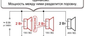
) it can be seen that with a 12 V supply at the output of the amplifier, the instantaneous voltage can ideally be from +12 V to 0 V; in this case it is simply impossible to go beyond the power supply limits. This voltage is supplied to the “+” terminal of the speaker. And the speaker output “-” is always tied to half the power, i.e. 6 V.
In Fig. b)
This voltage is shown in red. The amplitude of the sine wave Ua will ideally be up to 6 V. According to the formula, it turns out that the power of an ideal amplifier into a 4 Ohm load will be 4.5 W (at 8 Ohms up to 2.25 W, at 2 Ohms up to 9 W, but a 2 Ohm load is too heavy for most amplifiers). In practice, it is rarely possible to get even 4 W at 4 ohms without large distortions.
In Fig. V)
the usual output of an amplifier with single-supply power is shown; for clarity, the speaker and coupling capacitor have “swapped places”. Without a signal, the output of the amplifier is half the power, i.e. 6 V. Through the low resistance of the speaker, the capacitor is charged to the same voltage and without a signal, no current flows through the speaker.
When a sinusoidal signal is applied, the instantaneous voltage at the output of the amplifier will change from 0 to 12 V, but at the “-” terminal of the speaker a constant voltage of 6 V will be maintained and the entire voltage change will be applied to the speaker since at audio frequencies the resistance of the speaker is many times higher than the resistance capacitor (this condition will be violated at the lowest frequencies, which is why capacitors with a capacity of thousands of microfarads are installed here).
Instantaneous changes in voltage at the output of the amplifier are not enough to change the voltage on the capacitor; its charge is too large, it has a large “inertia”. There will be alternating voltage on one terminal of the speaker, and only constant voltage on the other.
To sharply increase the power, a “bridge” connection of the load is required; a pair of identical amplifiers, but operating in antiphase, is needed. Potentially the power output can increase by 4 times! In practice, everything is not so rosy; there are a number of problems. In Fig. G)
such a connection is shown. You must understand that you can’t jump beyond the power supply here either; you can’t get a voltage higher than the supply and/or lower than zero at the output of the amplifier (the same applies to bipolar power supply).
The trick here is that now BOTH speaker outputs will receive an alternating amplified signal voltage and go in “different directions”. Thus, the amplitude of the instantaneous voltage doubles. This doubling results in quadrupling the power.
In Fig. G)
at points A, C, E at outputs 1 and 2, half the power, i.e. 6 V, on the speaker the voltage is zero.
At point B on pin. “+” dynamics +12 V, on pin. “-” 0 V. This means that 12 V is applied to the speaker. At point D there is also 12 V, but of reverse polarity. So from a 12 V source they get a full swing AC voltage (double amplitude) of 24 V! Ua also doubled and amounted to 12 V ( Fig. e
). According to the formula, the output power will no longer be 4.5, but 18 W. Jump "over your head."
↑ How else to increase the power of UMZCH?
How else can you increase the output power? There are several ways, for example, a 2 Ohm load. But in practice this is difficult - the currents become large, they must be provided by the output stages of the amplifiers. Losses on wires, etc. increase sharply. The method works, but not in our case.
You can use... an output transformer, like in tube amplifiers, but on the contrary, not a step-down transformer, but a step-up transformer. Theoretically, you can get any power, but I have not seen this used in practice.
The most convenient way is a step-up supply voltage converter (Step-UP DC-DC). Then the supply voltage restrictions are removed.
By the way, you can connect 4 speakers to such amplifiers, but in this case you will need high-capacity output capacitors. You should pay attention to the polarity of connecting the speakers. Let's look at the example of TDA7379.
I see the advantage of such a connection in that the capacitors will protect the speakers in the event of a breakdown of the microcircuit.
↑ About the output power figures in the datasheet
Further. You can't ask these (and other) amplifiers to do more than they can. Don't trust advertising promises too much. The power stated in the datasheet is usually exaggerated. That is, this is a deception, but formally everything is correct. It is written that such and such power is at 10% distortion or even with a meander. This is true, but it is impossible to listen with such distortion - your ears will wither. Honest power - with distortion no more than 1...2%, and for these amplifiers it is 25...30% lower than with distortion of 10%.
You need to look at what load the amplifiers can operate with - 8 Ohms, 4 Ohms or even 2 Ohms. If an amplifier can drive a 2 ohm load, it can always drive a 4 ohm or 8 ohm load, but not vice versa.
I’ll get ahead and write that the TDA7266, TDA7297 microcircuits are capable of sounding stationary acoustics (there will be no disco), but this is not their profile. Their profile is bookshelf, computer, portable acoustics, including battery-powered ones.
Good nutrition is the key to success
The amplifier connection procedure begins with the power wires. Wiring is the most important element of a car audio system; the volume and sound quality depend on it. Amplifiers need a stable power supply, otherwise the power will not be enough and the sound will become distorted. To understand why you need to pay attention to the quality of wiring and how it affects the sound reproduced by a loudspeaker, you need to know what a music signal is.
Some suggest that it represents a sine wave, however, the musical sinhala is characterized by a large difference between the normal and peak value. If sharp signal bursts are not important for car speakers, then in the case of an amplifier the situation is completely different. If the signal exceeds the permissible power for even a second (or even a millisecond), then these “anomalies” will be audible even to those who cannot boast of a good ear for music.
If the car amplifier is connected properly, the signal will flow through the wires undistorted. Carelessly done work or incorrectly selected wire cross-section will result in the sound being more compressed, rough and sluggish. In some cases, wheezing may also be clearly audible.
How to choose a wire cross-section?
Wire is the most common metal with a certain level of resistance. The thicker the wire, the lower the resistance of the wire. To avoid sound distortion during large voltage fluctuations (for example, when playing powerful bass), you must install the correct gauge wire.
It is worth noting that the cross-section of the positive cable should not be larger than the negative one (the length does not matter).
An amplifier is considered to be a rather electrically intensive device. For its effective operation, high-quality grounding is necessary so that it is possible to receive the necessary energy from the battery. To choose the correct wire cross-section, you need to make some calculations. First, look at the instructions for the amplifier (or directly at the box from the manufacturer, if there is no documentation, use the Internet) and find the rated power value (RMS) there. Rated power is the signal power an amplifier can deliver over an extended period of time to one channel of 4 ohms.
If we consider four-channel amplifiers, they usually have a power of 40 to 150 watts per channel. Let's say that the amplifier you purchased produces 80 watts of power. As a result of simple mathematical operations, we find out that the total power of the amplifier is 320 W. Those. How did we calculate this? It’s very simple to multiply the rated power by the number of channels. If we have a two-channel amplifier with a rated power (RMS) of 60 W, then the total will be 120 W.
After you calculate the power, it is advisable to also determine the length of the wire from the battery to your amplifier and you can safely use the table to select the required wire cross-section. How to use the table? On the left side the power of your amplifier is indicated, on the right you select the length of the wire, go up and find out what cross-section you need.
The table shows the cross-sections of copper wires, remember that a large number of sold wires are made of aluminum coated with copper, these wires are not durable and have more resistance, we recommend using current copper wires.
Fuse selection
In order to secure the connection of the car amplifier, it is necessary to protect the power supply from the battery to the amplifier using a fuse. Fuses should be placed as close to the battery as possible. It is important to distinguish between a fuse that protects the device itself (whether it is an amplifier or a radio) and a fuse installed on the power wire.
The latter is needed in order to protect the cable itself, since a considerable current flows through it. Make sure that the fuse ratings match, since if the wiring fuse rating is too large, the wire may burn out as a result of a short circuit. If the rating, on the contrary, is less, then the fuse can easily burn out at the time of peak loads and then there will be no other choice but to buy a new one. The table below shows the wire cross-section and the required fuse rating.