yellow + with battery, red + with ignition switch. orange – to the dimensions/panel backlight (dims the radio backlight), blue – to the antenna amplifier, if any
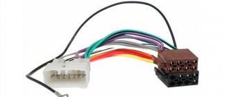
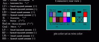
Accordingly, this is the counterpart to the connector that you have on the radio, you will have to buy it. Then everything is very simple: as a rule, the wires on this mating part are already marked: on the insulation it is written what kind of wire it is and where to connect it. The left half of the connector in the figure is the speaker outputs. They will say something like Front Left Positive, Front Left Negative, and so on. Left-Right is oddly enough left-right, Front-Rear is front-rear. It is best to find just such a block, especially if you are not planning a separate amplifier, and the speakers are connected directly to the radio.
Positive-Negative – it is important to connect them equally to all speakers. The wires of one channel have the same color, only one of the wires is solid color, the second is striped. That is, you need to connect, for example, all solid ones to the left terminals of the speaker, all striped ones to the right ones. If you mix it up, nothing will burn out, but the sound will be worse, because the speakers will work in antiphase; if you connect it correctly, there will be some kind of scene.
Next is the right half of the connector. Everything related to nutrition and management is here. I'll be in order.
Black wire. Big and thick. Weight. No comments. Yellow wire. Also big and fat. Main nutrition. It must be constantly connected to the battery, this is where the radio and its memory are powered. When you disconnect the yellow wire, all settings are reset.
Now about where to hook them. In the case of clinging to the cigarette lighter, or anywhere else to the existing wiring, then you won’t be surprised that “the radio flickers and turns off when I turn it on loudly,” because if you connect it, you’ll get exactly this kind of garbage. Look at the power wires - they are thicker than the others in the block for a reason. Also look at the radio fuse - 10A, no less. At peak loads, especially if it works on its own speakers, and not on the amplifier, it eats up a lot, and if the wire is thin, there is not enough current, and the voltage drops, the radio does not give the speakers the required power, it itself does not have enough power, the speakers wheeze , the radio is trying to turn off, it's complete bullshit.
Therefore: ideally, you take a wire with a cross-section no smaller than that on the block, ideally one and a half to two times thicker, and throw it directly from the battery to the yellow wire. Be sure to hang a fuse near the battery, with a nominal value again one and a half to two times greater than that on the radio (i.e. 15-30A). If you are too lazy to pull the wire from under the hood, cling to the ignition switch.
The power is connected. Further.
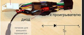
Red wire. ACC. Manager. The radio will turn on only if there is +12V on this wire. Made for bourgeois ignition switches, where there is an ACC position - all the electrics are on, but the ignition is not. There is no such provision in Tavria locks, so in principle this wire can be safely screwed in parallel with the yellow one. However, there is one thing - in some radios, when power is supplied to the ACC, the output stages of the amplifiers are turned on, and the current consumed by the radio increases. You can drain the battery very quickly. Is there such a thing in your particular radio - HZ, I protected myself by decoupling with two diodes.
The same is true for the ground wire. You also can’t attach it anywhere.
Connecting the following wires is optional; some may not be present at all.
Blue, white and blue striped - ANT and REMOTE. Control signals for external amplifier and electric retractable antenna. When the radio turns on, +12 appears on them. If you don’t have an amplifier and a retractable antenna, wrap electrical tape around the ends of the wires and leave them alone. One of the wires can be used to control the ACC, so as not to screw it to the power supply. You take two diodes with a current greater than 300 mA, twist the cathodes together, and connect the red wire there. You connect one of the blue wires to one anode, and to the second - the wire from the ignition switch, the one on which +12 appears when the ignition is turned on. As a result, to turn on the radio, you turn on the ignition, turn on the radio, and then the radio will work regardless of whether the ignition is on or not.
Here is a diagram of such a connection:
Orange. ILLUMINATION. Connects to side lights. When you turn on the headlights, some radios can make the backlight of their panel less bright, or turn on the backlight of the panel if the radio is turned off and the headlights are on. This is for convenience, so that in the dark the radio does not distract with bright light and is visible in the dark.
Decoding the wires of radio tape recorders for cars
Decoding the wires of radio tape recorders - designations, decoding of contacts and wires of car radios.
Acoustic group
R = Right speaker.L = Left speaker.FR+, FR- or RF+, RF- = Front right speaker (plus or minus, respectively).FL+, FL- or LF+, LF- = Front left speaker (plus or minus, respectively ).RR+, RR- = Rear speaker - right (plus or minus, respectively).LR+, LR- or RL+, RL- = Rear speaker - left (plus or minus, respectively).GND SP = Speaker common wire.
Radio power connector
- B+ or VAT or KZO or Vir+ or B/Up or B-UP or MEM + 12 = Battery power (plus)
- GND or GROUND or K31 or just a minus = Common wire (Ground), battery minus.
- A+ or ACC or KL 15 or SK or S-kont or SAFE or SWA = +12 from the ignition switch.
- N/C or n/c or N/A = No contact. (Physically the output is there but not connected anywhere).
- ILL or LAMP or sun symbol or 15b or Lume or iLLUM or K1.58b = Panel illumination. +12 volts are supplied to the contact when the side lights are turned on. Some radios have two wires, -iLL+ and iLL-. The negative wire is galvanically isolated from ground.
- Ant or ANT+ or AutoAnt or P.ANT = After turning on the radio, +12 volts are supplied from this contact to control the retractable antenna, if one is present, of course.
- MUTE or Mut or mu or the image of a crossed out speaker or TEL or TEL MUTE = Input to turn off or mute the sound when receiving a phone call or other actions (for example, reversing)
Other possible contacts in radios
Power Control = this is the control for turning on the amplifierP.CONT/ANT.CONT = this is the control of the antenna, power is supplied after turning on the radioILL + and ILL - = these are the wires for adjusting the brightness of the radio backlightAmp = Control contact for turning on the power of the external amplifierDATA IN = Data InputDATA OUT = Data OutputLine Out = Linear outputREM or REMOTE CONTROL = Control voltage (Amplifier)ACP+, ACP— = Bus lines (Ford)CAN-L = Bus line CANCAN-H = Bus line CANK-BUS = Bidirectional serial bus (K-line)SHIELD = Connection braided shielded wire.AUDIO COM or R COM, L COM = Common wire (ground) of the input or output of preamplifiers CD-IN L+, CD-IN L-, CD-IN R+, CD-IN R— = Balanced linear audio signal inputs with changerSW+B = Switching power supply +V battery.SEC IN = Second inputDIMMER = Changing display brightnessALARM = Connecting alarm contacts for the radio to perform car security functions (PIONEER radios)SDA, SCL, MRQ = Exchange buses with the vehicle display.LINE OUT, LINE IN = Line output and input, respectively. D2B+, D2B— = Optical audio link
Marking and color coding of wires
Let's look at the color code for car radio wires:
- Black (indicated by GROUND or GND) is the negative of the battery;
- Red (ACC or A+ marking) is the plus of the ignition switch;
- Yellow (indicated by BAT or B+) is the positive from the battery;
- White with a stripe (marked FL-) is the minus of the front left speaker;
- White without a stripe (indicated by FL+) is a plus of the front left speaker;
- Gray with a stripe (marked FR-) is the minus of the right front speaker;
- Gray without a stripe (indicated by FR+) is a plus for the right front speaker;
- Green with a stripe (marked RL-) is the minus of the left rear speaker;
- Green without a stripe (designation RL+) is a plus for the left rear speaker;
- Purple with a stripe (marked RR-) is the minus of the right rear speaker;
- Purple without a stripe (designation RR+) is a plus for the right rear speaker.
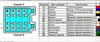
Next, you can see how the car radio connector is pinned out.
Pinout diagrams for radio tape recorders from popular manufacturers
Wiring of linear outputs on a standard radio can be done using two RCA connectors. This option is the most common, since power amplifiers have the same sockets. The pinout of connectors for Pioneer car radios contains from 10 to 20 contacts. Their purpose depends on the model of the multimedia device. For example, in the KEH series, the first pin is the antenna control, the second pin is the voltage from the ignition switch, etc. The speakers are connected to pins 3, 4, 5, 6, 8, 9, 10 and 11.
What are the wires used for and where do they go?
Types of USB connectors
Wires for car radios are used to connect to a power source, speakers and amplifier, remove control signals and implement service functions. Thanks to clear identification by color, the likelihood of making a mistake when connecting is reduced, since it is clear which wires go where and what they are needed for.
Orange
The orange wire (ILL) is most often used to control the backlight of the car radio display. It connects to the parking light switch. In this case, several backlight control scenarios are possible. For example, you can make its brightness automatically decrease when the side lights are turned on.
Yellow and red
According to the generally accepted standard, the yellow and red wires are used to connect the positive pole of the power supply to the car radio. Through the first of them, constant power is provided to the device’s microcircuits along with the audio power amplifier and display backlight. When voltage is applied to the yellow cable, all functions of the car radio begin to work. Often, its break is connected to a fuse in a housing that matches the type. The higher the output power of the car radio, the higher the rating of the fuse link.
The red wire, constantly connected directly to the battery, provides continuous power to the volatile memory chip, which stores radio stations recorded by the owner, car radio parameters and the place where listening to music from the media was stopped. The yellow wire is often connected not directly to the on-board network, but through the ignition switch. Thanks to this approach to power supply, the current consumed by the receiver is reduced several times.
Blue and pink
The blue wire is used by some manufacturers to control a motorized antenna. It is supplied with power when the radio mode is turned on. When the radio is turned off, the antenna is automatically retracted, since it contains an additional relay, which is powered directly from the battery. Another purpose of blue is to enable additional functions. For example, the Reverse wire on the radio is used to activate the parking sensors or rear view camera mode.
Pink is used to implement various service functions. One of them is blocking multimedia functions on a 2-din radio with a video player. The control signal is most often supplied from the warning lamp switch under the parking brake lever. As soon as the pink cable is connected to ground, it becomes possible to start the video player or turn on the TV tuner. Otherwise an error message will appear on the display.
Blue - white
The blue-white cable (blue wire with a white stripe) is designed to control the power of the active antenna. It is often marked with a tag marked “Remote”. This cable also supplies a control signal to the car amplifier. The connection can be made either directly to the device or through a special relay.
How to connect a radio
If the instructions or reference label are lost, then before connecting the car radio correctly, you need to check the purpose of the wires using a tester, a suitable current source and a low-power 12-volt light bulb. First, the wires intended for connecting power are recognized.
This procedure also needs to be done if they have different colors than the standard or are not equipped with fuses. For safe detection, you can use a 9-volt battery as a power source. Its negative pole is connected to the car radio body. The positive terminal of the battery is connected in turn to each cable of the car radio. On an old radio, you also need to press the switch or turn the volume control.
At the moment of connection to the cable intended for supplying power, a weak spark will jump between the contacts. If the battery is fully charged, the backlight will light up faintly. On modern radios, the correct connection of the circuit can be confirmed by pressing the Power button. After this, the power will turn on.
Then the wires that give current relative to the minus (radio casing) are determined. To do this, connect a 12 V current source to the previously recognized contacts to supply power. A 10 A fuse must be included in the positive gap in order to increase safety.
A light bulb or tester rated for 15 V or more is connected to the cassette recorder body and alternately to the remaining cords after turning on the device. If the arrow deviates and the light comes on, then the wire is intended to power the antenna or remotely control the amplifier. All cables identified by color must be clearly marked.
How to properly connect to an electronic device
The concept of an interface as we know it today dates back to the 1960s. More precisely, in 1964, when the company developed its legendary IBM System/360 mainframe. It was then that the main tasks of any interface - physical or virtual - were formulated. They were to provide a standard connection for all devices.
Euro connectors
Initially, only a few types of standard inputs could be made to ensure compatibility between products from different manufacturers. This was a PS/2 port for the keyboard, an LPT port for the printer, and a connector for the PCI card. Nowadays, each type of connection has its own standard interface; this approach greatly simplifies the development and sale of any type of device and allows you to understand their built-in capabilities. Here are descriptions of the main communication elements, first of all, the designation of the button on the radio, which are used on the panels of Pioneer and other car radios.
Types of branded connectors
Description of the buttons on the front panel of the radio for control (decoding)
| Button labels | Button function |
| A.F. | Different RDS frequency, automatic search when reception is poor |
| ALL OFF | Everything is off |
| AMS | Music sensor, works on the principle of playing a number of tracks equal to the number of clicks |
| ANG | Panel adjustment |
| ATA | The radio turns on automatically when you turn off and rewind media tracks |
| A.T.T. | Quickly reduces volume |
| BAND | Selecting a radio receiver |
| BEER | Enabling sound when pressing buttons |
| Blank Skip | Skips pauses longer than 8 seconds |
| BMS | Compensates for low frequencies when dropped due to the main device |
| BTM | Remembers the quality frequency of strong stations |
| CLK ADJ | Adjusts time |
| COLOR | Color |
| DISP | Display activation |
| DNPP | Selecting a CD in the changer |
| DNPS | Entering disc names |
| DSP | Activating the sound processor |
| EJECT | Remove the cassette from the cassette receiver or disc |
| EON | Reception of traffic information |
| FUNCTION | Switches the most used functions |
| INTO SCAN | Plays the recording for 10 seconds to search |
| LOS | Looks for stations, skipping with weak reception |
| LOUD | Tone compensation |
| M.RDM | Disc random playback |
| P.I. | Automatic search |
| PI SOUND | Switching to another frequency |
| PI MUTE | Muffled sound |
| POWER | Shutdown |
| PS | Listening to saved settings |
| PTY | Selecting a genre |
| RDS | Search for a station by metadata |
| RDM | Play disc tracks in any order |
| REG | Switching to the frequency of a radio station with RDS |
| Repeat Play | Replaying a track |
| SCAN | Scanning tracks and playing the beginning |
| SEL | Settings |
| SHUFFLE PLAY | Play available music in random order |
| SYSTEM Q | Tracking sound enhancement factors and showing them on the display |
| TA SEEK | Searching for a station with RDS |
| TC | Calling the tuner when rewinding |
Antenna connection
Having a radio in the car, some car enthusiasts prefer to listen to music or watch videos. But many drivers like to listen to their favorite radio stations while on the road, which is why every car audio system has an FM tuner. An external antenna is required for its normal operation. Experts recommend installing an active module that ensures stable reception of radio stations. The antenna is powered from the car network via the radio.
Chinese audio devices are equipped with a special output labeled ANT. Depending on the settings, power may be supplied to the antenna when the radio is turned on or only to the radio. The antenna cable is connected to a special socket located on the back wall of the device. The receiving part is located on the windshield. The active antenna is connected with 3 wires:
- Weight. It is connected to the car body or to the standard terminal on the GU body.
- Power wire. Connects to the red wire of the device control.
- Antenna wire. Connects to the corresponding socket on the radio.
In the case of installing a simple receiving device, an antenna adapter containing an amplifier is additionally used to improve the quality of the received signal. In radios with a GPS module, an active GPS receiver is used, which ensures stable operation of both the navigator and the radio. Connects similarly to an active antenna for a car radio.
general information
Do-it-yourself repair of Chinese pioneer car radios
AMP is a technology for accelerated mobile pages, which is developed by independent developers and actively promoted by Google in its search engine. Yandex has not yet joined this initiative, but I am sure that soon they will either implement this standard or come up with something similar in operating principle.
The bottom line is that the site uses special tags, the number and functionality of which are strictly limited. The developer's task is to assemble a hodgepodge of available schemes that will solve the customer's problem.
Pages with AMP rank higher than other queries in search due to the fact that they meet the requirements for fast loading and are adapted for mobile devices.
In fact, all such pages are static or conditionally dynamic, since they allow the use of form submissions, as well as iframes.
Next, I’ll tell you about the main features of AMP.
Dimensions
There are two main form factors for radios, these are 1-DIN and 2-DIN (DIN (abbr.) - German Deutsches Institut für Normung eV . - German Institute for Standardization).
The depth is not standardized, but is usually 160 mm. for both options.
Today, replacing a 1-DIN radio with a 2-DIN and vice versa is not difficult, the presence of a huge number of adapter frames contributes to this, thanks to our Chinese brothers!
Connecting an ISO type car radio
PCI pinout
When all the necessary tools are ready for work, you can start connecting. Next, we will look at how to properly connect a car radio with an ISO connector. A special diagram will help us with this, on which you can see which wires are responsible for what and where they go. So, for example, on the left side of the diagram the power connection for the car radio is shown, and on the right is the output to the speakers.
Let's start with connecting the power, since it is at this stage that most mistakes are made. Three wires are responsible for powering the car radio, each of which performs a specific function.
Yellow wire for 12V
This wire is the main one, since it is responsible not only for powering the built-in amplifier, but also for saving the car radio settings. When connecting it, you must use a 10 amp fuse, and the approximate length of the wire should be 30 cm. In addition, yellow wires marked B+, BU or BATT are very common. They can also be used.
Red ACC wire
This wire is responsible for controlling the power of the car radio. Simply put, power will be supplied to the radio only when the ignition key is in the desired position. Surely you have noticed more than once that when you turn the key to the ACC position in the car, the stove, cigarette lighter, radio and other devices start up.
Black wire GND
The wire marked GND is connected to the negative terminal of the car battery. Some car enthusiasts prefer to connect it to the car body, but this is only relevant in cases where the car radio has low power
It is also very important when connecting the GND wire to the car body, thoroughly clean the connection point, thus ensuring good contact
When the car radio is provided with power, you can proceed to the output to the speakers. For this purpose, there are also special wires that are laid to one or another column:
- Front Left (FL) – front left speaker
- Front Right (FR) – front right speaker
- Rear Left (RL) – rear left
- Rear Right (RR) – rear right
It is worth noting that some car radios have not only wires like FL, FR, and so on, but also so-called tulip connectors. If your speakers are equipped with these types of connectors, you can use them for connection. Otherwise, you need to know which other wires are responsible for what.
White ANT wire
The wire with this marking is responsible for controlling the car radio's antenna. Depending on the signal quality, it supplies power to the internal active antenna or to power the external antenna.
Wire marked ILL (Illumination)
The color of this wire may vary depending on the manufacturer. Most often this is a light pink or yellow version of it. The wire marked ILL is connected to the side lights, to positive. It’s easy to guess that it is responsible for the car radio’s backlight.
MUTE
Responsible for muting the sound when a button is pressed.
Settings
Setting up GPS on car radios
So, the correct setting of such a car radio is already a guarantee of normal operation. To carry it out, you just need to have the instructions at hand. Below is the setup process:
The car radio connects to the network
When connecting, it is recommended to pay special attention to the gray wire marked BRAKE. It is responsible for disabling protection from watching TV and DVD programs while the car is moving; The next wire is also very important
Viscous coupling repair
It is marked AMP-CON. This very wire is responsible for connecting and controlling external sources.
Car radios with GPS navigator
- The required software is written to the SD card. If, for example, it is IGO8, a popular software today, then the resolution in the car radio is set through the menu to 480x234 pixels. After that, insert the map and open the main GPS menu. Select "options".
- Once in the settings, you need to select a navigation program. But for this you will need to specify the path to the SD card to be launched. Only after this will it be possible to turn on the navigation program.
Data filtering
Every AMP page has a state. It can be thought of as an object with a hierarchy of properties. The page state can be changed in event handlers using the AMP.setState function.
Let's add a filter that allows you to display only bikes that are in stock. To do this, we will place a checkbox on the page, by clicking on which we will change the state of the page, assigning a value to the onlyAvailable variable (in accordance with whether the checkbox is selected or not). The name of the variable is arbitrary, it could be called anything
Please note that AMP has its own way of handling events. You can handle multiple events at once, and you can have multiple actions for each event
The data binding mechanism allows you to link page state variables with property values in HTML markup. In order for the AMP library to do this binding, the name of the property that should receive the value must be enclosed in square brackets - . For example, we will add or remove the CSS class 'active' (this is a non-standard class and is set by us) depending on the value of the onlyAvailable variable.
In development mode (#development=1), the page state can be printed to the browser console using the AMP.printState() function;
Now let's add a list of products to the page state. To do this, we will use a separate amp-state component. The component will load data from the same source as amp-list, but re-loading will not occur, since AMP controls data loading and avoids unnecessary requests. In addition, we will add a macro that, when the value of the onlyAvailable variable changes, will filter the list of products.
Now let's use the filtered list as a data source for the amp-list component. To do this, we connect the src property of the component with the filteredBikes macro. We will also connect the height property of the component with the number of elements. This is necessary because the height of the amp-list component will not automatically adjust to the number of elements. In this example, the number 340 is the height of the product card, and 16 is the padding at the top and bottom.
Please note that explicit loading of data by setting the src="https://localhost:3000/api/bikes" property remains. You can't remove it
When loading an AMP page, data binding is not automatically performed for performance reasons. It will be executed only after user actions, such as clicking on a checkbox.
Open the resulting page and check that filtering is working correctly.
Review of car radio Timeless TID 9301
Car radio with GPS navigator
Let's consider one of these car radios. It differs in the following technical characteristics:
- The screen of the device is motorized 7 inches. Has a resolution: 1440x234 pixels;
- GPS navigator is built into this head unit;
- The car radio supports ipod (see How to connect an ipod to the car radio with your own hands);
- It has an AUX jack on the front panel;
- A radio tuner operating in the FM/AM bands is built into the car radio;
- It is possible to connect the controls to the buttons on the steering wheel;
- There is a separate camera output;
- The device comes with a block with wires, instructions, a remote control, wires for USB, a mounting frame and special tools for removing the radio.
Connection
Let's now find out how to connect this device. Using the same example, you can connect other car radios similar in parameters to this one. Let’s begin:
As in the case described above, we ground the gray wire to disable the protection for watching DVD programs;
The window lifter does not work - do it yourself repair of window lifter buttons on a Renault car
Car radio with GPS navigator and its connection
We use the AMP-CON wire, designed to control external sources.
In addition to the wires described above, the car radio has built-in connectors for connecting AV wires. In particular, there is an input for Camera IN, where the wire from the rear camera is inserted, there are outputs for the rear and front channels, audio and video, and so on. In this case, colored wires are used.
The front console of the car radio is a panel containing the following components:
- The display is single-line, thanks to which short information is displayed (if the LCD screen is removed). This very display has 7 types of backlight;
- Here, on the front console, you can find a Bluetooth receiver (see Bluetooth for car radio: do it yourself);
- To open the LCD panel there is an OPEN button;
- There is also a volume control, microphone, AUX jack and much more;
- Placed on the front console and SD card slot;
- There is also a mode switching regulator on the front panel, and a mini USB on the right side.
It is interesting that this same model of car radio can be easily installed on a VAZ 2105. There are no problems with installation, although some parts of the dashboard will still have to be cut out. Knowing how to configure GPS car radios with your own hands is very useful. You can save a lot of money on the services of specialists, who sometimes charge such prices that it’s scary to even think about. The main thing is to do everything according to the instructions, do not ignore video reviews and photo materials.
Pinout of a standard Euro connector
The Euro connector is a standard plug for many modern devices. An ISO plug is installed on the machine, thanks to which it becomes possible to connect any model of radio with the appropriate connector.
Standards 1DIN and 2DIN
The difference between the standards lies in the size of the devices: a 2-din device is 2 times higher than a 1-din device.
The most common are 1-DIN radios, because Installation of higher devices due to the lack of a seat of appropriate size on the front panel of the car is not possible in every car.
There are 2 types of radio tape recorders:
- With proprietary connector. You need to choose a product whose pinout matches the desired car.
- With universal connector. The device connects directly to the ISO socket provided in the car.
Pinout is carried out according to ISO 10487 standard.
Upper power connector A
The connector serves as a connector between sources and consumers of electricity from the on-board network.
Plugs 1, 2, 3, 6 are rarely used in radio circuits of the lower and middle price segments. The elements are used when connecting additional options in higher quality player models. Wire colors may vary.
You should understand the purpose of the contacts:
- ANT. Used with a retractable antenna.
- Remote. Designed for connecting external amplifiers. Thanks to it, you can increase the number of mounted speakers, which is necessary in the interiors of large cars.
- Illumination. Adjusts the brightness of the player screen (the higher the driving speed, the less intense the backlight, so as not to distract the driver).
- Mute. Adjusts the sound of the device.
- A4. Turns the audio system on and off.
This connection scheme allows you to protect the battery from discharge, because turning on the system is possible only when you turn the ignition key, while the acoustic cascades consume electricity even when turned off.
The pinout of the ISO connector of the radio (European) looks like this:
- Connector A5 (blue) is for the antenna. If the permissible current value (300 µA) is exceeded, both the amplifier stages and the entire head unit may break.
- Wire A7 (red) is intended to power the head unit. When it is disabled, the settings are returned to factory settings. Voltage - 12 V.
- Cable A8 (black). Responsible for connecting the speaker system to the car.
To protect the audio system, the wires must be equipped with a fusible link. If interruptions occur in the operation of the player, you should place a capacitor between connectors A7 and A8, which will act as a filter, smoothing out fluctuations in the electrical circuit.
Bottom speaker connector B
The speakers are connected through it as follows:
- Rear right + (purple).
- Rear right - (black and purple).
- Front right + (gray).
- Front left - (black and gray).
- Front left + (white).
- Front left - (black and white).
- Rear left + (green).
- Rear left - (black and green).
Most devices are designed for 4 channels; 8 wires are used for this (2 pieces per speaker).
The sound quality of the system depends on the “flattening”. If you mix up the connectors, the device will not fail, but the radio will not work correctly.
Audio system elements should be connected with cables with a cross-section of 1.5 mm or more. Thicker wires are used on power lines.
Standards 1DIN and 2DIN
The differences between them are the height of the radios. The number 2 in the designation of the 2DIN standard indicates that the height of a double-DIN receiver is 2 times greater than a device made according to the 1DIN standard. The latest radios are now the most popular and widespread. Installation of double-din radios is not possible in every car, since an appropriate seat must be provided on the front panel.
All car radios are divided into two types: with a proprietary connector, most often made in the form of a plug, and located on the rear wall, and with a universal ISO connector. In the first case, you should purchase a proprietary connector for the radio, the pinout of which matches the desired model. If the machine has an ISO socket, then the other end of the proprietary cable should also have an ISO plug. In the second case, the radio is connected directly to the ISO socket located in the car.
When replacing the radio with another one, you should look at the back wall and determine which block is located there. After this, you can decide whether to purchase a proprietary plug or you can connect the device to the machine through an already installed ISO socket. The pinout of the car radio connector is carried out according to the ISO 10487 standard.
Designations, decoding of contacts and wires of car radios.
Acoustic group:
R = Speaker right. L = Speaker left. FR+, FR- or RF+, RF- = Front speaker - right (plus or minus, respectively). FL+, FL- or LF+, LF- = Front speaker - left (plus or minus, respectively). RR+, RR- = Rear speaker - right (plus or minus, respectively). LR+, LR- or RL+, RL- = Rear speaker - left (plus or minus, respectively). GND SP = Speaker ground.
Power connector for radio:
B+ or BAT or K30 or Bup+ or B/Up or B-UP or MEM +12 = Battery powered (plus)
GND or GROUND or K31 or just a minus = Common wire (Ground), battery minus.
A+ or ACC or KL 15 or SK or S-kont or SAFE or SWA = +12 from the ignition switch.
N/C or n/c or N/A = No contact. (Physically the output is there but not connected anywhere).
ILL or LAMP or sun symbol or 15b or Lume or iLLUM or K1.58b = Panel illumination. +12 volts are supplied to the contact when the side lights are turned on. Some radios have two wires, -iLL+ and iLL-. The negative wire is galvanically isolated from ground.
Ant or ANT+ or AutoAnt or P.ANT = After turning on the radio, +12 volts are supplied from this contact to control the retractable antenna, if one is present, of course.
MUTE or Mut or mu or the image of a crossed out speaker or TEL or TEL MUTE = Input to turn off or mute the sound when receiving a phone call or other actions (for example, reversing).
Other possible contacts in radios:
Power Control = this is the control for turning on the amplifier P.CONT/ANT.CONT = this is the control for the antenna, power is supplied after turning on the radio ILL + and ILL - = these are the wires for adjusting the brightness of the radio backlight Amp = Control contact for turning on the power of the external amplifier DATA IN = Data input DATA OUT = Data output Line Out = Line output REM or REMOTE CONTROL = Control voltage (Amplifier) ACP+, ACP- = Bus lines (Ford) CAN-L = CAN bus line CAN-H = CAN bus line K-BUS = Bidirectional serial bus (K-line) SHIELD = Shielded wire braid connection. AUDIO COM or R COM, L COM = Common wire (ground) of the input or output of preamplifiers CD-IN L+, CD-IN L-, CD-IN R+, CD-IN R- = Balanced line inputs of the audio signal from the SW+ changer B = Power switch +B battery. SEC IN = Second input DIMMER = Changing the brightness of the display ALARM = Connecting alarm contacts for the radio to perform car security functions (PIONEER radios) SDA, SCL, MRQ = Communication buses with the car display. LINE OUT, LINE IN = Line output and input, respectively. D2B+, D2B- = Optical audio link
Connector pinout (decoding)
The connector pinout is the only element of the power interface that has an individual circuit. In other words, the interface is always different and depends on the specific model of the radio, but the pinout designation of the radio is always the same. The description is usually given in the documentation.
Connector pinout
There are methods for determining pin outputs experimentally if it is impossible to obtain an original description of the contacts. This is typical for Chinese devices produced under fly-by-night brands. The need for restoration is often necessary, since the device turns out to be of really good quality and can still be used for media purposes.
Detailed description of connectors
Description of control connectors
The operating instructions contain the usual diagram with symbols, the description of which is given below. The data should take into account the names of the radio contacts that are located on the rear panel. There is no universal option, since the more interfaces, the more extensive functionality is supported. Pioneer practices a large number of interfaces, others do not.
But quantity is not a panacea, but only one of the options for interface elements. The best way to understand what has been said is with the help of an illustration showing connectors for ToyotaPrado. The designations on the pinout are described in the instructions for the radio and are given below.
Name of wires and power outputs of the car radio
| BAT, K30, Bup+, B/Up, B-UP, MEM +12, BATTERY | Battery powered |
| GND, GROUND, K31, minus | Wire to ground |
| A+, ACC, KL 15, SK, S-kont, SAFE, SWA | Power supply from ignition |
| N/C, n/c, N/A | Blank contact |
| LAMP, 15b, Lume, iLLUM, K1.58b, “sun”. In some cases there are two wires -iLL+ and iLL | Panel illumination, usually +12V is supplied when the side lights are turned on. Some car radios |
| Ant, ANT+, AutoAnt, P.ANT, ANTENNA AMP | Connecting 12V to an external or active antenna |
| MUTE, Mut, mu, “speaker crossed out”, TEL, TEL MUTE | Contact for muting the speaker when receiving a call. |
| GALA, GAL | Speed sensor input |
| KL.15 FEEDING | Constant pressure |
| NAV AUDIO IN +/- | Navigator input |
| AUX GND | Ground output to AUX |
| CENTER SPEAKER | Central speaker |
| LEFT FRONT, LEFT REAR SPEAKER | Left speaker |
| RIGHT FRONT, RIGHT REAR SPEAKER | Right speaker |
| AUX GND, L+, R+ | AUX |
| CAN L, CAN R | CAN bus |
| M-BUS with wires M-SCK, M-BUSY, M-DATA. | M-BUS is used to connect a CD changer. |
The above list is not exhaustive. Car radio interfaces are the concern of manufacturers, so the decoding of the wires is always individual and is given in the instructions for each car radio. Contacts, as already mentioned, and their number depend on the functionality of the car radio and control features, and therefore are considered the prerogative of the manufacturer.
Shaping and Indexing Data: index and extent
You must define the data values and declare the shape of the data before you can run the kernel code. All data is defined to be an array (rectangular), and you can define the array to have any rank (number of dimensions). The data can be any size in any of the dimensions.
index Class
The index Class specifies a location in the or object by encapsulating the offset from the origin in each dimension into one object. When you access a location in the array, you pass an object to the indexing operator, , instead of a list of integer indexes. You can access the elements in each dimension by using the or the .
The following example creates a one-dimensional index that specifies the third element in a one-dimensional object. The index is used to print the third element in the object. The output is 3.
The following example creates a two-dimensional index that specifies the element where the row = 1 and the column = 2 in a two-dimensional object. The first parameter in the constructor is the row component, and the second parameter is the column component. The output is 6.
The following example creates a three-dimensional index that specifies the element where the depth = 0, the row = 1, and the column = 3 in a three-dimensional object. Notice that the first parameter is the depth component, the second parameter is the row component, and the third parameter is the column component. The output is 8.
extent Class
The extent Class specifies the length of the data in each dimension of the or object. You can create an extent and use it to create an or object. You can also retrieve the extent of an existing or object. The following example prints the length of the extent in each dimension of an object.
The following example creates an object that has the same dimensions as the object in the previous example, but this example uses an object instead of using explicit parameters in the constructor.
Selecting a car radio
Translation into Russian
Today, the problem of choosing a car radio does not seem to be as big a task as it was a few years ago. In recent years, a huge number of worthy companies have appeared that offer really high-quality radios at an affordable price. Finding an interesting option in terms of price-quality ratio is really not a problem, so the only question that remains to be decided is which car radio will be installed in your car.
As a rule, modern radios are divided into two parts. These are single-din, or as they are also called, single-block, and double-din. The first option is most common in our country and in Europe. Two-block radios are most popular in countries such as Japan, America and Korea. The main difference between each type is only in their size. Double-din radios are twice the size of single-din radios, which allows manufacturers to make models with a larger touch screen, as well as introduce more multimedia functions.
It doesn’t take long to choose the size of a car radio, because if you own a car with a 1-DIN radio, then installing a double-din version simply won’t work. However, some car enthusiasts manage to reorganize the space so that the 2-DIN type option still fits on the front panel. But this is a topic for a separate article, and now let’s talk about how it is possible to install a car radio with your own hands.
Accelerating Code: Tiles and Barriers
You can gain additional acceleration by using tiling. Tiling divides the threads into equal rectangular subsets or tiles. You determine the appropriate tile size based on your data set and the algorithm that you are coding. For each thread, you have access to the global location of a data element relative to the whole or and access to the local location relative to the tile. Using the local index value simplifies your code because you don't have to write the code to translate index values from global to local. To use tiling, call the on the compute domain in the method, and use a tiled_index object in the lambda expression.
In typical applications, the elements in a tile are related in some way, and the code has to access and keep track of values across the tile. Use the tile_static Keyword keyword and the to accomplish this. A variable that has the tile_static keyword has a scope across an entire tile, and an instance of the variable is created for each tile. You must handle synchronization of tile-thread access to the variable. The stops execution of the current thread until all the threads in the tile have reached the call to . So you can accumulate values across the tile by using tile_static variables. Then you can finish any computations that require access to all the values.
The following diagram represents a two-dimensional array of sampling data that is arranged in tiles.
The following code example uses the sampling data from the previous diagram. The code replaces each value in the tile by the average of the values in the tile.
Blue wire
English-Russian translation TRADE-IN
The blue wire provides a control signal to the antenna amplifier or electric drive, which extends the signal receiver pin out of the wing cavity. If the car is not equipped with such equipment, the cable is carefully twisted and insulated. The colors of the wires located on the antenna electric drive unit depend on the vehicle modification.
Blue insulation is also used to protect the cord, which is needed to control an external amplifier. A similar color scheme is used on Sony head units. When the player is activated, a control pulse is sent through the “remote” cable, which ensures the start of operation of the external amplifier and acoustics. After the engine is turned off and the radio stops working, the amplifier is automatically de-energized, ensuring that the vehicle’s battery remains charged.
Blue-white wire
Blue and white insulation colors are used to mark cables used to control low-current external equipment. A positive signal appears on the cable only after the head speaker is turned on. The permissible current transmitted through the cord does not exceed 200 mA. Under increased load, overheating and irreversible destruction of the electronic controllers located inside the player occurs. If the user intends to switch powerful equipment, then it is necessary to introduce a unloading relay into the circuit.
Pink wire
A set of wires for a car radio may contain a cable covered with a pink protective layer. The element is used on head units capable of playing video. Used to switch an external rear view camera, providing signal broadcast. When using this type of equipment, signal compatibility must be ensured, otherwise the display image will be upside down.
To provide power to the camera, a Reverse wire is used, which allows you to enable signal transmission when using reverse gear. The cord is connected to the power supply circuits for the reversing lamps. When using standard parking sensors, it is possible to connect the cable to the controller connector.
An additional harness can be used in the design of the head unit to reduce the sound volume when reverse gear is engaged. The same cable, covered with a yellow-black insulator, is responsible for turning off the broadcast when a phone call arrives. If the car is not equipped with a cell phone connection unit, the cord is not used.
The harness also includes 8 cables intended for connecting rear and front speakers. When using component acoustics, it is necessary to connect the elements to a common channel, while controlling the resistance and power. All negative outputs from the speaker coils must be fed to the appropriate connectors on the amplifier.
To install the low-frequency speakers, a separate wire is used, laid independently. On some cars, the subwoofer is a standard device, located in the niche for the spare wheel or the internal cavity of its disk. Separate cables are used for switching; the color of the insulation depends on the vehicle model.
On standard radios there is a flat cable designed to transmit information to the display, located in a separate pocket on the instrument panel. The harness consists of a large number of wires covered with white and gray insulation. The protective layer ensures the solidity of the product. The cable is secured with special clamps that ensure reliable contact and protection from moisture.
Some Pioneer head units have an additional cable designed to connect a security system. The cord is connected to the plug, the commutation point is designated Alarm. Using a digital CAN or K-Line bus on a car requires connecting the radio to the circuit. For this purpose, separate cords are used, connected to a common connection connector.
Key Features
Let's list the main features and connections to the radio that write service messages:
- power connector for connecting the battery;
- “ground” (common wire);
- ignition switch power supply;
- panel lighting;
- 12V power supply for automatic connection of the retractable panel when the engine is running;
- the already mentioned TEL or TEL MUTE to turn off the music during a call;
- connector for speed sensor.
This Tel “Silence” connector is a standard feature, so it can be found in devices from other brands. For example, the LG LAC-M1500 has this option, as well as a number of other models. Some car radios have a button on the front panel that allows you to manually mute the sound. In Swing models, this function is located on the Phone button. In devices that are not new, there is often a problem with a wire or contact sticking. Then the indicator not only lights up constantly, but the sound does not turn on. In the mentioned Swing, this issue is resolved by disabling the button.
Many owners change speakers and amplifiers because other buttons do not respond additionally. The functionality of the device is simply blocked. In some cases, this is due to the peculiarities of the electrical network of the on-board system; such a malfunction will imply permanent failure of the components of the media system. In this case, only a professional technician can help, who will sort through the on-board system and connect the radio correctly.
Pioneer usually connects a speed sensor; in the vast majority of cases, premium brands provide power for the antenna. Mute translation into Russian in the radio is “mute” or in the sense of “turning off”, it is used by Russian drivers quite rarely, which leads to sticking of the connectors. As you know, our drivers often do not know English and can rarely translate into Russian with the same meaning. We recommend that if you have English instructions, you obtain and print the Russian equivalent.
Amplifier purpose
At the initial stage, it is necessary to decide what the car enthusiast wants to get in the end. Typically, when installing a car amplifier in a car, two goals are pursued:
- improving the quality of the audio signal output from the car speakers;
- increasing the overall volume of music tracks.
Car amplifier
A car amplifier is a universal device that allows you to increase the output signal level. In everyday life, many people use home theaters that include an amplifier. But household appliances typically use a 220-volt power source, while automotive systems are powered by a 12-volt on-board network. That's why such amplifiers are called automobile amplifiers.
Car radio service messages
Pioneer car radio service messages are designed to notify the driver about connected functions in real time, usually without translation if there is no firmware. The presence of a service mode allows you to control the connection of additional systems and devices to the vehicle’s on-board system, as well as check their functionality. In other words, if you are buying a device, it makes sense to understand some of its functions. From experience, this is very convenient, since the functionality is carefully thought out by engineers.
The Pioneer Mute radio provides muting the sound during a phone call. It can be connected automatically when there is a signal or manually using an indicator. Many drivers not only do not use these features, but have also not heard of such functionality; as a result, the connector remains unused, and in some cases, pinched by the rear panel. More often, the problem with the indicator is typical for car radios that are not entirely new, which require routine inspection.
Yellow wire
The yellow wire has an increased cross-section of the core and thicker insulation; it is intended for connecting the head unit with the battery; power is supplied in a constant mode. Thanks to the increased diameter, current is supplied without the risk of overheating the element. To protect the equipment from short circuits in the circuit there is a standard blade-type fuse. The device is placed in a socket on the rear wall of the radio, the rating depends on the power of the built-in amplifier.
When using a separate wire connected to the positive terminal of the battery, it is recommended to additionally protect the circuit. The fuse is mounted in a separate housing at a distance of 300-400 mm from the battery terminal. The cable is laid along standard wiring harnesses; plastic clamps are used to connect the cords into a single trunk. For entry into the cabin, standard holes available in the engine panel of the car are used.
Yellow and red wire
The yellow and red wires are responsible for supplying positive power. The difference between the red wire (which has a larger cross-section) is the method of switching through the ignition switch. Turning the key to the ACC position provides a positive 12V signal to ensure operation of the device. A direct connection of the cable to the positive pole of the battery is allowed, but in this case the radio remains in the active state and contributes to accelerated battery discharge.
The cable with red insulation ensures that the head unit settings are saved when the ignition is turned off. If the connection is incorrect, the player's parameters are reset, which have to be configured again after each start of the car's power unit. To connect to the negative pole of the battery (body), a conductor covered with black insulation is used. The cable is routed to the nearest ground bolt welded to the body. Fastening is done using a clamp, which is tightened with a 6-sided nut.