The idea has long been around to build a sound amplifier with really good parameters and a stylish design. I selected several of the most interesting module designs posted on the site, connected them, and this is how this amplifier was created. I made the entire design of the ULF myself, unfortunately, without having any sensible measuring equipment.
The idea was simple - to get high-quality sound and a beautiful view. The amplifier is deliberately devoid of unnecessary circuits and modules, such as tone or gain control. Instead, it includes a relay-based input selector, which shortens the signal path. And a large VU meter, which gives it an interesting look.
The advantage of the amplifier is that everything is implemented on a modular basis. If it fails, it can be disassembled into individual modules in 10 minutes and then reassembled. Here is the list of blocks:
- Main power module
- Preamp Power Module
- ULF protection module
- Power amplifier modules
- Pre-amplifier modules
- Input/output selector module
- VU-METER module
Amplifier
I looked at a lot of power amplifier modules, from TDA to strange tube-chip hybrids. But I decided to use this scheme for this purpose. The voltage gain here is about 30 dB. I think that this is a rather troublesome amplifier to assemble, the circuit is not simple, but it worked, and after several attempts to configure the module came to life.
The biggest problem was with finalizing the board, that is, finding components. All the parts are new and getting them turned out to be a little more difficult than I thought. The only change on the board is the replacement of transistors T3, T4 BF470, transistors BF472. After assembling the module, I set the quiescent current to 50 mA with a symmetrical supply of +/- 55 V. I installed the amplifier boards vertically to the radiators.
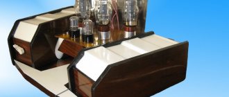
10 W tube amplifier
In the world of HI-FI, the tube amplifier has come back into fashion. Friends persuaded me to design a tube amplifier, because, in their opinion, my age obliges me to do so, since the first third of my professional activity occurred precisely in the tube era.
I built my first tube amplifier over 35 years ago. Since then, the quality of electronic components has improved significantly, and measurement technology has also become more advanced, but some parts have disappeared or their acquisition has become very difficult. The main problem is that over time, the requirements for the technical parameters of the amplifier have increased.
Just think about harmonic distortion, which is considered one of the main characteristics of amplifiers.” In the early 60s, amplifiers with distortion of about 1% were considered HI-FI (DIN45500 standard). Modern semiconductor amplifiers have two to three orders of magnitude less distortion.
When designing, the first step was to choose the type of output stage. To achieve a relatively low-cost design, a design that does not place extreme demands on the most expensive part, the output transformer, is desirable.
From this point of view, final stages with cathode or partially cathode connection of the transformer are suitable. Such final stages are characterized by the fact that the load resistance is partially or completely included in the cathode circuit of the final stage lamps. Local negative feedback within the final stage creates low output impedance, which helps resolve problems created by the output transformer.
Such a connection is also beneficial from the point of view of “technical” safety, since when the load is turned off, there is no voltage surge on the output transformer, and it does not break through, as often happens in “traditional” terminal stages.
Among the possible output circuits, the choice was made in favor of the so-called double-coupled amplifier, in which, of two identical, relatively simple output transformers, one is connected to the anode and the second to the cathode circuit of the final lamps. Another initial design issue was the choice of the type of final amplifier tubes, since this determined its output power.
I settled on EL84 lamps, which, when selected in class A mode for low distortion, allow an output power of 10 W. This is not that much power, but, as my experience shows, 3-4 W is enough to sound a room of 20 m2. The tube itself is relatively easy to obtain, and due to the low anode voltage, the filter capacitors in the amplifier are also relatively cheap.
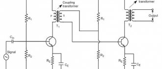
Final tube power amplifier with dual coupling. The functional diagram of the final stage is shown in Fig. 1. It shows only the elements that are important from the point of view of understanding the operating principle. The two output transformers are absolutely identical. Their primary windings “from the point of view” of the terminal lamps are connected in series, the secondary windings are connected in parallel.
The impedances of the primary windings should be taken at half the optimal equivalent load resistance and the secondary windings - twice as large. The voltage gain of the final stage lamps is two, which is an advantage compared to the push-pull output (PPP - Parallel Push-Pull). Thanks to this, in our case only half the control voltage is required.
When considering Fig. 1, we will assume that the winding directions of the two output transformers coincide, and the secondary windings are correctly phased. In this case, the cathode and auxiliary grid of the upper lamp are connected to the upper terminals of the output transformers, and the anode, due to phase reversal (rotation by 180°), is connected to the lower terminal of the transformer (crosswise).
Providing the highest possible control voltage for the final lamps is facilitated by the circuit for switching on the preliminary stage lamps, which is obtained by connecting the anode resistors of these lamps not with the positive supply voltage, but with the corresponding “hot” ends of the output transformer.
The pre-amplification stages are symmetrical. In front of them there is also a symmetrical cascade of the anode-cathode phase inverter (also called cathode). The negative feedback circuit is also symmetrical and acts from the primary windings of the cathode output transformer to the cathodes of the preliminary stage lamps. The bass reflex is excluded from the feedback loop, since it operates with deep local feedback.
Negative feedback further reduces the output impedance of the end lamps, which is already low due to the presence of local feedback. In other words, the output transformers are powered by a voltage generator. In this case, nonlinear distortions in the output transformers, arising due to the nonlinearity of the core magnetization curve (B-H curve), are reduced to a negligible value.
This method of introducing feedback has a beneficial effect on the circuit from the point of view of high-frequency stability of the amplifier, since the leakage inductance of the output transformer is excluded from the feedback loop, resulting in one less pole in the loop. It may seem like a disadvantage that such feedback does not “correct” the transformer's transmission of high frequencies.
More precisely, this device does not change the upper limit frequency (at low power). However, feedback cannot also change the width of the frequency range. The power frequency range depends solely on the output transformer, so you need to make an output transformer of appropriate quality. The role of capacitors connected between the auxiliary grid and the cathode of the final lamps may seem mysterious.
There would be no need for them if the output transformers were ideal. there was no active resistance in their windings. Since this is not the case, we can imagine that between the auxiliary grids and the ideal transformer there is a resistance at which, during operation, an alternating voltage appears, the phase of which coincides with the phase of the signal generated at the anode and is opposite to the phase of the signal at the cathode. As a result, the efficiency of the lamp decreases and approaches the efficiency of a triode. This undesirable effect is eliminated thanks to the specified capacitors.
The output transformer is the most expensive component of a tube amplifier, on which its quality largely depends. Around output transformers 30-40 years ago, in the “heroic era” of the overwhelming dominance of tube amplifiers, there were many “dark places”. For semiconductor amplifiers, the output transformer is not a problem, and much is forgotten about them.
Because of this, in my opinion, we should dwell in more detail on output transformers. The following applies, of course, not only to the output transformers of this amplifier, but is true for any push-pull output transformer. The output transformer determines the frequency range of the amplifier. When the output transformer is connected to the negative feedback loop, the maximum power generated by the end lamps does not increase.
On the contrary, in the case of low output powers, feedback can expand the frequency range, because in this case there is a power reserve in the end lamps. Therefore, it is customary to indicate the frequency range of tube UMZCHs with an output power of 1 W (usually keeping silent about this). Frequency range by power means that we specify the frequency limits at which the amplifier, along with its rated distortion, delivers at least half the rated output power (-3 dB).
In our case, I unconventionally took a harmonic distortion limit of 0.1% to get closer to similar data from solid-state amplifiers. What determines the frequency range of the output transformer? In other words, what determines in what frequency range the output transformer provides the optimal load resistance for the final tube?
From the equivalent circuit of the output transformer, it can be established that the lower frequency limit is determined by the inductance of the primary winding of the output transformer, and the upper limit is determined by the leakage inductance (neglecting the self-capacitance of the windings).
Leakage inductance
where Kp is the dispersion coefficient; C is the inductance of the primary winding. Kp is a number less than 1 and is often multiplied by 100 and expressed as a percentage. This is the “dissipation” of the output transformer. The leakage inductance of a transformer can be determined by measuring the inductance of the primary winding with the secondary winding short-circuited.
It is easily confirmed that the ratio of the lower and upper limit frequencies of the output transformer, to a first approximation, coincides with the dissipation coefficient. The dissipation of a “traditional” small-sized tightly wound transformer is about 2-3% if the secondary winding is on top. Things are a little better if the secondary winding is located below.
This means that the ratio of the lower and upper cutoff frequencies (taking a dispersion of 2.5%) is approximately 1:40. For example, with a lower frequency of 100 Hz, the upper limit frequency is 4000 Hz. The situation is not very comforting, is it? Therefore, dispersion must be reduced. What determines the dissipation factor of the output transformer? From the geometry of the coils, i.e. from the shape of the coils and from the winding method.
This means that the core affects the width of the frequency range only depending on which coil can be put on it, provided the geometric dimensions are the same. In this case, the type of core practically does not matter.
A more detailed examination of the issue reveals that the dissipation coefficient is inversely proportional to the coefficient, which depends on the sectioning of the coil, traditional for winding output transformers, and is directly proportional to the “slimness coefficient”, i.e. the longer and the lower the transformer coil.
Therefore, it is not customary to fill the window of the output transformer to capacity with winding. Then the “slimmer” coil creates less dispersion. My goal was to design an output transformer that was easy to manufacture, so I asked myself: Is there a type of transformer that has the thinnest coil possible?
Yes, there is, it is a toroidal transformer, which has a long, low, and therefore “slender” coil. Having examined a factory-made 230/12 V network toroidal transformer, I determined Kp = 0.1%, which is 25 times better than the traditional design of this transformer. If we also take into account the fact that with the chosen circuit, the leakage inductances of the two transformers are connected in parallel, i.e. If the effect is created as if the output transformer has half the total leakage inductance, then the situation is very encouraging.
For the sake of completeness, it should be noted that the picture is still not entirely cloudless. Regardless of whether we reduce dissipation by sectioning the coil or “slimming” it, the intrinsic capacitance of the output transformer increases. When reducing dissipation by these methods, the self-capacitance can increase so much that the upper limit of frequencies will no longer be determined by the dissipation inductance, but by the self-capacitance of the primary winding.
It should also be noted that the low-frequency power limit for the output transformer is determined not by the inductance of the primary winding, but by the saturation of the core. This is fully consistent with my measurements. On the other hand, the lower limit frequency at low power is determined by the inductance of the primary winding, so in practice it is always lower (sometimes much) than the lower frequency at high power.
With the upper limit frequency the situation is more complicated. The inductance Lp limits the frequency limit in the same way at both low and high power, while the self-capacitance primarily determines the high frequency limit at high power. Harmonic distortion data is contained in the table.
In addition to the technical data, I will make the following remark. In a tube amplifier, it is customary to set not the output impedance of the amplifier, but the damping factor. The damping factor is the ratio, expressed in decibels, of the nominal load impedance to the amplifier's output impedance (measured at a given frequency).
In this case, this means that the output impedance of our amplifier is 0.6 ohms, which is a good value on a “tube scale”, but significantly higher than the output impedance of solid-state amplifiers. Output impedance is an important characteristic that significantly affects the transmission of sound frequencies near the resonant frequency of loudspeakers.
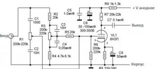
It follows that data on resistance measured at the traditionally indicated 1000 Hz does not give anything, but the value near the resonant frequency of the loudspeaker is significant. The schematic diagram of the amplifier is shown in Fig. 2. The input signal goes to bass reflex V1 (EF86). This bass reflex has good symmetry and is resistant to supply voltage fluctuations and lamp aging. For complete symmetry, it is required that the operating resistances of the anode and cathode circuits of the lamp be the same.
This explains the presence of resistor R2 in the anode circuit, since in the cathode circuit, to set the operating point of the lamp, resistor R4 is needed, which sets the bias voltage. Those who want to fine-tune the amplifier can replace R2 with an adjusted resistor (trimmer) of 2.2 kOhm, and use it to set the minimum distortion in the middle of the frequency range, say, at a frequency of 1 kHz. This can compensate for the asymmetry of not only the bass reflex but also the amplifier stages that follow it
For the symmetry of the bass reflex at high frequencies, the reactance of the loads is of great importance. The capacitive components of the loads include distributed mounting capacitances, but the dominant ones are the input capacitances of the two halves of the V2 lamp, as well as the large Miller capacitance. In the case of the ECC83 lamp with large asymmetry, an increase in distortion is observed at frequencies of 10-20 kHz.
By connecting a trimmer capacitor with a capacity of 20-30 pF to the appropriate lamp grid, asymmetry can also be compensated for at high frequencies. The symmetry of V2 can be checked by measuring the cathode voltage of both halves of the lamp. A voltage deviation above 0.1V-0.2V indicates V2 asymmetry.
I hasten to note that for my amplifiers I did not use any settings, did not apply compensation, they completely correspond to the given diagram. The most important task of the next block is to create a large control voltage for the final amplifier tubes. For this purpose, the classic option is to use the ECC82 lamp.
A common cathode resistor R17 for the two halves of the lamp improves the symmetry of the cascade. When connecting the anode resistors (R19 and R22) to the “hot ends of the primary winding of the transformer Tg2, the signal phase in which is the same as on the anodes V3, an additional “pull-up” of voltage occurs (voltage boost). Resistors R20 and R21 in the grid circuits of the final stage lamps V4 and V5 prevent the occurrence of stray currents; they are connected directly to the lamp sockets using the shortest possible wires.
These currents can appear if capacitors shunting the auxiliary grids of the terminal lamps are connected to the lamp sockets with long wires. Due to the inductance of the wires connected to the auxiliary and control grids, due to the “cross-shaped” connection of the anodes, a counterclockwise oscillator can arise, and the cascade will begin to self-excite.
To eliminate self-excitation with ceramic capacitors with a capacity of 1...5 pF, we connect the auxiliary lamp grids with their cathodes (directly on the lamp panels). In my amplifiers, the need for these capacitors arose, but in other manufacturing they may not be needed, so I did not indicate these capacitors on the diagram. The installation of the end lamps in class A mode is ensured by cathode resistors R23 and R24.
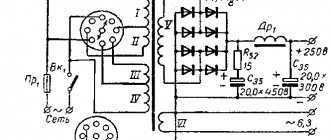
A deviation of the voltages measured across these resistors of less than 0.3 V indicates satisfactory symmetry of the operating points of the final stage lamps (the emission of the lamps differs slightly). In order to improve symmetry, it is recommended to select end lamps. The anode voltage of the amplifier is provided by a traditional unstabilized power supply. As a rectifier, I used a Graetz rectifier (bridge) on semiconductor diodes.
The disadvantage of this solution is that after turning on the power, the anode voltage appears on the lamps much earlier than they heat up. This means an increased load on the cathodes when heated. To solve this problem, I installed a separate switch K2, which switches the anode voltage.
This gives another advantage - during setup it is easy to “free” the amplifier from high voltage without stopping the heating, so that after switching on you do not have to wait for the lamps to heat up again. The operating state of the amplifier can be indicated by LEDs (they are not shown in the diagram).
Anode voltage filtering is provided by a multi-link RC circuit. At the nominal mains voltage, the anode voltage of the final stage lamps is 250 V with fluctuations within 1...2 V. Fluctuations in the filament voltage are within 1...2 V. It is necessary to monitor the voltage dropping in the wires. In the unfortunate case (small cross-section and large length), this voltage drop can be significant.
Design. First, a few words about the mechanical design of the chassis. In the absence of a bending device, I used a 1.5 mm thick aluminum plate as a chassis. Its drawing is shown in Fig. 3. The amplifier housing is made of polished black chipboard 19 mm thick. The two end sides are made so that they are higher than the lamps.
At the same time, tube protection is guaranteed even if you turn the amplifier over to get to the bottom of the chassis. The dimensions of the two end plates are 170x135 mm, and the two side plates are 310x50 mm. A 2.5 mm wide groove runs along the inside of the case on all sides; the edges of the chassis fit into it. The groove is located at a height of 43 mm from the bottom of the case.
I cut the groove with a table saw; its blade cut a fairly wide rebate. To connect the end plates to the side plates, furniture bolts with a diameter of 5 mm with an internal hole for a key were used. For connection, one bolt per side is sufficient, since the edge of the chassis that fits into the groove protects it from rotation.
I made two channels of the amplifier using traditional wall mounting without the use of printed circuit boards. The design of the amplifier is not particularly critical to the arrangement of the elements, but the end lamps, in order to prevent their overheating from mutual radiation, should not be located closer than 100 mm from each other (in a closed housing).
The amplifier uses 1% resistors with a power of 0.6 W, with the exception of R25 - 2 W. Separating capacitors are polypropylene or polyester, with an operating voltage of 400 V. Electrolytic capacitors in cathode circuits have a permissible voltage of 16 V. the rest - 350 V. Please note that the indicated permissible voltages are sufficient even in the case when the anode voltage appears immediately ( before the lamps heat up).
The output transformers (toroids - they were manufactured by URBAN Elektronik) are located on a common vertical axis, one above the chassis, and the other below, near the end lamps. When assembling an amplifier, a painstaking task is the correct connection of the output transformers. To do this, you need to identify the winding terminals.
First, the halves of the primary winding are connected in series, an alternating voltage of about 6 V (50 Hz) is applied to the secondary winding, and the total voltage on the primary winding is monitored using a voltmeter. The halves need to be connected so that double the voltage is obtained.
Carefully! Dangerous voltage appears on the primary windings!
This operation is performed on both transformers. It is very likely that the terminals of two transformers manufactured at the same time are located in the same way, but control will not hurt. At the second stage, you need to phase the windings of two transformers. The specific direction of the windings is not important, it is only important that both transformers are turned on in phase. We provide the terminals of the secondary windings with marks and during installation we turn them on accordingly (in parallel so that the marks coincide).
We supply an alternating voltage of 6 V to the secondary windings of both transformers. We connect the terminals of the primary windings in series and measure the voltage between the two remaining free terminals. If the transformers are turned on in phase, then this voltage is less than 10 V, if not, then it is doubled (relative to the voltage on one primary winding).
Then, to achieve the correct phase, you need to swap the leads of the primary winding of one of the transformers. After phasing, we mark the terminals of the primary winding connected during the measurement process, and consider these terminals to be the lower terminals in the diagram according to Fig. 2.
Using an oscilloscope, we monitor the phase of the input and output signal on a working amplifier (at the terminals of the secondary windings). By switching (if necessary) these terminals, we set the same phase of the input and output voltage. Now the amplifier is non-inverting.
To make setup easier, I can indicate the constant voltages in the main circuits. At the cathode V1 - 38 V, at the anode - 152 V, at the cathode V2 - 1.2 V, at the anode - 165 V, at the cathode V3 - 8 V, at the anode - 171 V. At the cathode resistor V4 (V5) - 7.2 V, between the anode and cathode - 250 V. On the first filter capacitor C12 - about 274 V, on the second - 263 V, on the third - 225 V, on the fourth - 190 V. The indicated values are measured at the rated mains voltage.
Grade. As stated above, the design described was created for the purpose of comparison. I was interested in how competitive a well made tube amplifier was compared to a good solid state amplifier. I used amplifiers in a system with a separate low-frequency subwoofer channel to power two satellites transmitting a range above 100 Hz. For comparison, I took a well-proven final amplifier based on complementary field-effect transistors.
Due to the different sensitivity of the two types of final amplifiers, it was necessary to change the sensitivity of the low-frequency channel accordingly. During the comparison, I did not change anything else in the system; the preamplifier was transistorized. The results of these experiments can be summed up as follows: a tube amplifier sounds no worse than a semiconductor amplifier.
From a CD (of good quality), it produces a more transparent, clean sound picture than a solid-state amplifier. On the other hand, with an untuned CD player (Philips bit-stream), the tube advantage disappears. In any case, it appears that, despite the higher harmonic distortion factor, this amplifier is competitive with the transistor amplifier. Whether to credit this to a tube amplifier or consider it a disadvantage of a transistor amplifier is up to you, dear reader, to decide.
Power supply
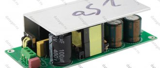
The power supply circuit is a classic 500W (VA) toroidal transformer with dual 2x 40V secondary windings and current up to 7A. The voltage is rectified by a 35A/1000V bridge rectifier and then filtered by 6x 10000uF/63V capacitors. I soldered additional 100 nF / 100 V decoupling capacitors to the bridges. However, such a large transformer, when connected to the network, consumes a significant inrush current necessary to magnetize the core. The solution to this problem was a soft start circuit.
In a nutshell, it works in such a way that the relay contacts close approximately 2 seconds after the device is turned on. Meanwhile, current begins to flow through the limiting resistors. The delay time depends on the capacitance of capacitors C2 and C3.
ULF circuit
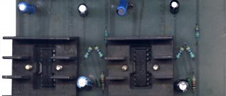
Circuit from the TDA7297SA datasheet
A more beautiful color scheme option
The power circuits are connected to a car battery or to a 12 volt stabilized power supply. The positive contact goes to pins 3 and 13, and the minus contact goes to 8 (GNDP - power supply ground) and 9 (GNDS - audio signal ground). The left and right stereo inputs are connected to pins 4 and 12 respectively via 2.2 µF filter capacitors (to remove the DC component of the signal). The soft start is performed using 47k resistors and a 10 uF capacitor.
Printed circuit board
The current consumption in standby mode is about 50 mA, and during St-by shutdown it is about 100 μA.
Protection
The circuit used combines several useful functions, including protection against DC voltage at the amplifier output, eliminates clicking when turning on and off, and additionally protects everything from overheating by turning off the speakers when the temperature is above 85 degrees on the radiator. The circuit itself is powered directly from the main transformer, a protection circuit.
Power supply for 12 V and ULF Hi-Fi class on PAM8610. Power – 2X10 Watt
Once upon a time, audio amplifiers (ULF) were large, with a bunch of tubes, huge radiators for transistors, and heavy transformers in the power supply. But life does not stand still. Now compact microcircuits with digital ULF have replaced tube and transistor dinosaurs in almost all consumer devices. You can easily design a compact amplifier, for example on the PAM8610 chip. The power supply from the review was used for power supply. The ULF on the PAM8610 exists in several versions and is quite inexpensive. You can buy it here, for example - https://www.banggood.com/12V-Mini-Hi-Fi-PAM8610-2X10W-Audio-Stereo-Amplifier-Board-Dual-Channel-p-933675.html. It was decided to use a ready-made board with a volume control and soldered connectors. There is also an ultra-budget option. It was reviewed here on the website -. Why this particular amplifier - price and very good impressions of the younger models PAM8403/PAM8406: Review 1, Review 2, Review 3, Review 4. Let's see how the older amplifier model performs. Module characteristics:
Power supply 7-15 V, recommended 12 V Power up to 10 W per channel with a load resistance of 8 Ohms Protection against short circuit, overheating Amplifier efficiency up to 90%
Judging by the description, excellent characteristics for such a baby.
Photo: The flux is a little not completely washed off.
The speaker connections are not indicated in any way. It was found out empirically and using a similar slightly different board:
Power plug - , around - “-“
The microcircuit under the heatsink of this amplifier version is good. Jumpers on the board - one temporarily turns off the sound (mute), the second I don’t know.
To power the structure, it was decided to use the power supply from the link at the beginning of the review. This power supply was reviewed in great detail. Another 12 Volt power supply, but this time at 1 Ampere. The power supply works well in extreme conditions, is compact and inexpensive. Theoretically, you can get a total power of about 12 watts per two channels with this power supply. Or real about 5 watts per channel. I was satisfied with this power supply and the ULF power. For greater amplification of the microcircuit when using a signal source in the form of a cell phone or DAC, it is necessary to use preliminary amplification in front of the microcircuit, which I did not want to do. And 5 watts of power per channel is enough for my purposes. But we will still test the ULF and PSU microcircuits in different modes and on loads of different resistances.
Power unit:
To test the load we use powerful resistors 4 Ohm, 6 Ohm, 8 Ohm per 100 Watt:
You can buy them here 4 Ohm 6 Ohm 8 Ohm
We connect all modules and resistors.
We take measurements. The amplifier supply voltage is 12 V, a 1000 Hz signal from a sound generator is supplied to the input. Power is calculated by the square of the voltage at the output of one channel of the amplifier (measured with an AC voltmeter) with a connected load divided by the load resistance
First group of tests
Normal source (phone or DAC). Uin = 0.15 V. Testing was carried out on the power supply from the review, without preliminary amplification. In all cases, the overheating protection on the microcircuit and the current protection on the power supply did not work.
I have speakers with a resistance of 4 Ohms - the first line is my mode of using the amplifier.
Second group of tests
Disabling the power supply from the current protection review. We increase Uin until the protection on the power supply is triggered. This mode is possible when using a pre-amplifier (for example, this one) before the amplifier from the review
Third group of tests
Limit mode. A laboratory power supply is used. The tests are completed if the amplifier chip turns off due to overheating (the temperature of the chip in this case is more than 100 degrees Celsius). In reality, to implement this mode, you need a more powerful power supply (12 V 2 A for example) and preliminary signal amplification.
I think more power than stated was achieved using a radiator on a ULF chip.
The tests may be useful if you are going to use this ULF chip for your amplifier or make a powerful portable speaker with a preamp and a powerful battery.
Chip heatsink temperature. The radiator here is good. But there are versions of this board without a radiator.
Temperature at resistors:
If there is such a temperature here at 9 Watts, then what will happen when testing a 100 Watt amplifier?
Sine wave test. We apply a 1000 Hz sinusoid to the input and use an oscilloscope to see what we have at the output of the amplifier.
18+ Readers with unstable mental health should not watch
Amplifier input:
Output at very low volume:
Average volume level:
Sine wave at maximum. The ULF chip is on the verge of shutting down due to overheating.
I was surprised by the results - the younger PAM8403/PAM8406 output with a sine wave is ok. Maybe I mixed something up when measuring. I went online and found a video review of a similar microcircuit - video review. True, your friend there did not connect a load to the output and carried out tests without a preamplifier (he did not bring the microcircuit to its maximum modes).
After completing the tests, I decided to refine everything. Components for assembly:
The nexx 3020 router is used as a Logitech Squeezebox Player. I asked for it in the same way as the review. A toggle switch was also made for a regular linear input. The case was purchased offline for 400 rubles - the cheapest in terms of price-size-quality ratio.
It turned out like this:
Initially, a 12->5 V DC converter based on a PWM controller was installed. But I had to install a second 5 V power supply for two reasons: 1. Interference. I removed the ground loops, but some interference (possibly from the converter) remained. 2. In case of overload, the power supply is switched off by protection - the router is overloaded and this is not good - it takes a long time to overload.
Summary: My mini Hi-Fi system:
For my tasks (sounding the bathroom and corridor), the power of the power supply and the sound quality from the ULF are quite enough.
Addition. 1. Link to datasheethttps://www.alldatasheet.com/datasheet-pdf/pdf/246508/PAM/PAM8610.html 2. About HiFi - That was sarcasm. It’s strange that the people in the comments didn’t immediately understand the sarcasm and reacted seriously.
The product was provided for writing a review by the store. The review was published in accordance with clause 18 of the Site Rules.
Preamplifier
The entire amplifier was supposed to be a tube/MOSFET hybrid. I used a cheap, proven circuit with one ECC85 tube (analogs are possible) as a preamplifier. I ran the power cables using twisted pairs. The grounding circuit in the amplifier is serial and is connected to the housing only at the input, at the location of the lowest potentials. The preamplifier will start working approximately 2 minutes after switching on. I wanted to extend the life of the lamps as much as possible.
Input selector
I implemented it on one of the most interesting projects. It has four line inputs and one output. There are plans to add an additional input for the platform in the future. The signal from any input stops at the relay until the selector switch sends a signal to the CD4017 chip, which, in turn, controls the transistors and the voltage on the coil of that relay. The signal then goes to the preamplifier and the power amplifier. This circuit also has a separate power supply, like the preamplifier.
Other photos of the amplifier
Tests have demonstrated exceptionally high sound quality, and the volume is quite sufficient for sounding a workplace or a small room.
- TRIODE AMPLIFIER
- SIMPLE ULF CLASS A
- LOW DISTORTION AMPLIFIER <0.001%
- TUBE ULF FOR 6P14P AND 6N2P