High-quality amplifier 100W+100W
Structurally, the amplifier is made in an aluminum case and includes four main blocks: two channels of final amplifiers, a power supply and speaker protection.
Audio amplifiers are made according to the popular, and one might say already legendary, scheme “Slap in the face of mikruham Mark.II”, the developer of which is Ilya Stelmakh (Nem0).
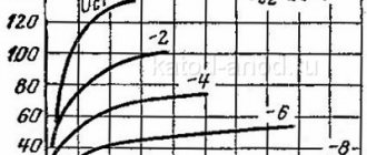
Amplifier circuit OM Mark . II
Main technical characteristics of OM Mark . II
Attached to the article is a ULF printed circuit board in the “LAY6” format. On this board you can assemble a more updated “Slap in the face of mikruham 2.5” circuit.
OM 2.5 diagram and main characteristics
Components
I used film capacitors as non-polar capacitors, with the exception of C3-C5 - ceramic ones. It is advisable to use a non-polar electrolytic capacitor as C2, which is what I did.
Electrolytic polar capacitors must be designed for a voltage greater than the supply voltage by 20-30%, so I used 50V capacitors.
All resistors with a power of 0.25W with the exception of R26-R29 and R30, their power should be 2W and preferably they should not be wire-based.
As R3 and R16, on the recommendation of the author of the circuit, I installed multi-turn trimming resistors. They allow you to smoothly and easily set the quiescent current and smoothly set the zero constant component at the ULF output.
I set the Chinese volume control to 100 kOhm, I couldn’t find anything else. Having looked through seven of them, I still couldn’t find any channels with the same resistance. If possible, do not use this type of variable resistors, otherwise when you turn the knob, a signal will be heard in one column, but not yet in the other, that is, not symmetrical adjustment. The resistance of the volume control can be from 20 kOhm to 100 kOhm.
The transistors must be original, otherwise excitations are possible or the amplifier may not start at all, or even fail upon startup.
The author suggests the following transistor replacements:
I did not replace them with analogues, but installed only the transistors indicated on the diagram on the board.
I secured transistors VT9, VT13, VT14 to the heat sink through insulating gaskets to prevent contact of their collectors with the radiator.
Amplifier power
My source is a switching power supply with an output voltage of ±36V at idle, which provides an output power of 200W. I described its design in the article “Reliable SMPS for an amplifier.”
The voltage ±36V (at full load ±31.5V) was selected in such a way that the amplifier develops a power of 50W+50W into an 8 Ohm load, without distorting the sine wave at the output.
On the OM2 printed circuit boards, I reduced the power supply capacity of electrolytic capacitors, or rather, some electrolytes were replaced with small capacitances of film capacitors. This action was aimed at preventing the activation of the SMPS protection at startup. I have a little more than 1000 µF left in each arm, which is more than enough for a 200 W pulse source.
The SMPS has short circuit protection, which is very useful when setting up and testing the amplifier.
Speaker protection
If the transistors of the final stages OM2 fail, the speaker system will receive supply voltage and the speaker will fail. To eliminate this unpleasant situation, I used speaker protection from the Brig amplifier, described in the article “Protection of speaker systems.” The protection works perfectly when a DC component appears at the amplifier output, starting from a voltage of ±1.5V. In addition, the protection provides a delay when turning on, this eliminates the appearance of various clicks and other transient processes in the acoustics when power is supplied to the device as a whole.
I organized the protection power supply through a half-wave rectifier from the secondary winding of the pulse transformer, and also removed the electrolytic capacitor for power supply on the protection board, and instead put a 330nF film capacitor. These actions ensured that the acoustics turned off almost instantly when the device's power was turned off, eliminating the clicking sound in the acoustic system when turned off.
Amplifier design
For one channel OM2 (OM2.5) a heat sink with a surface area of 700×1000 cm2 is required, so the device body was chosen with side radiators with a surface area of 850 cm2.
As mentioned above, transistors VT9, VT13, VT14 are installed on radiators through silicone gaskets. There is no need to place insulating bushings on them, since the design of the transistors prevents the mounting screw from touching their flanges.
All boards are mounted on 6mm and 8mm brass standoffs, which are screwed to the bottom cover of the chassis.
The PCB does not provide a connection between the signal and main grounds, so a jumper must be installed, otherwise the amplifier will not work.
The device body is connected to the common wire of the power supply in only one place.
To minimize interference on low-current signal wires passing from the RCA inputs (tulips) to the input part of OM2 (OM2.5), these wires are twisted into a twisted pair. Also, to reduce radiation from power wires (power supply, acoustics), these wires are also twisted.
For the same purpose, the volume control, with a resistance of 100 kOhm, is placed as close as possible to the RCA sockets. For this, a shaft with a diameter of 6 mm was used.
Initially, the shaft rotated in contact with the aluminum insert, which caused interference due to friction and at medium volume, when the regulator was rotated, the speaker protection was triggered. To eliminate this defect, a fluoroplastic washer was installed.
At first I wanted to install screens between the OM2 and SMPS boards, but with this amplifier layout, high-frequency background is not heard in the acoustics, as fans of linear power supplies assume.
The front panel has a power-on LED, powered from the positive bus (+36V) through a 6.8kOhm 0.5W resistor.
The rear panel has RCA jacks and banana jacks for connecting speakers. All sockets are installed through insulating sleeves and washers; under no circumstances should the sockets come into contact with the chassis body.
Setup and first launch
Attention!!!
If you repeat this circuit, then before the first start, you need to unscrew the slider of the trimming resistor R3 to the middle. Trimmer resistor R16 must be unscrewed so that there is maximum resistance between the base and emitter VT9.
After a ten-minute warm-up, we close the amplifier inputs to the common wire, or turn the volume control to minimum. Next, we install the DC millivoltmeter probes between the emitters VT13 and VT14, and by rotating the R16 slider, we set it to 30-60mV, which corresponds to a quiescent current of 60-130mA with a resistance of R26-R29 of 0.47 Ohm. I set the voltage drop across the emitter resistors to 50 mV, their total resistance is 0.47 Ohm.
Total, Irest = 50 mV/0.47 Ohm = 105 mA.
By connecting the DC millivoltmeter probes to the output of the amplifier, rotating the R3 slider, we set the DC voltage to 0 mV.
After that, I connected the speaker system and ran it at medium volume for 10 minutes, and then repeated the settings again.
Run and test
Since I designed my device for an 8-ohm load, I installed an 8-ohm resistor at each output. The resistors are pressed against the heat sink.
I applied a sinusoidal signal with a frequency of 1000Hz 0.65V to the input. Gradually, turning the volume control to maximum, I brought the amplifier to its maximum power, at which the top of the sine wave is not yet cut off (no clipping). The voltage across the resistors was 19V, which corresponds to a net power of 45W per channel with a load resistance of 8 Ohms. The maximum power of each channel in clipping was 65W.
I ran the amplifier at a power of 50W+50W for 20 minutes, the side radiators heated up to 500C, this is quite normal. The Schottky diodes on the SMPS heated up to 1050C, the transformer to 650C, while the top cover of the chassis was closed.
Such heating of the SMPS is normal, since taking into account the efficiency of OM2 equal to 55%, the power supply supplied power of 180 W to almost a static load (sine). When listening to music programs, the heating will decrease significantly.
Amplifier excitation
If you, like me, assembled the amplifier efficiently, washed off the remaining flux, and the amplifier gets excited (clicks, squeaks, humming, increased heating are heard), then this may be caused by low-quality components or other reasons. I noticed excitation of one channel when measuring power.
At about the maximum power, the bottom of the sine wave looked like this:
The author of the circuit gives several recommendations to solve the problem of self-excitation:
By increasing C5 to 44pF, the signal became clear and beautiful. Thanks to comrade Nem0 for the diagram and recommendations!
Overall, the amplifier works great, sounds powerful and rich.
The circuit, printed circuit board and characteristics of the OM2 (OM2.5) amplifier are taken from the “[Nem0] Audio Engineering and Radio Electronics” community.
Printed circuit board OM2 (OM2.5)
Recommendations for selecting parts
With the TDA7294 it is difficult to achieve the desired 100 W. Therefore, a 120 W transformer is quite suitable. With it, a power of about 2 x 60W and no more can be achieved.
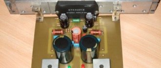
In general, having played enough with TDA and LM, we recommend looking towards STK4241 or STK4050 . They are truly more powerful and better sound amplifiers. As for LM or TDA, they cannot even be compared with STK in terms of distortion coefficient. So if you are going to make a really decent amplifier with a power of 2 x 100 W, do it with two STK4050 (according to the passport, they will safely issue 200 each). In the process of amateur radio practice, a total of 10 amplifiers were made on STK, and no one let us down.
In Moltiwatt 11 housing
These are probably one of the most popular low-frequency amplifiers in this type of housing, which were used in car radios in the late 90s.
Probably from them this thing came from 10+10+10+10 Watts or 25+25 Watts. On radio tape recorders they write on the case.
- TDA 7496S
- this is probably one of the least powerful of the series. Stereo 5+5 watts; - TDA 7377A
- 4 outputs of 6 watts, or 1 output of 28 watts via a bridge circuit; - TDA 7266M
- 7 watt mono, 3-18 volt power supply; - TDA 2004
- popular, 2 outputs of 10 watts, from 8 to 18 volts of power; - TDA 7497
- three 10-watt outputs, but requires bipolar power supply; - TDA 7297M
- two outputs of 15 watts each, this is a double bridge; - TDA 7265
- 25+25 watts; - TDA 7295S
- 80+80 watts, two channels; - TDA 7293
- 100 Watts per output; - TDA 7294M
- 100 Watts per output.
List of circuit components
- 0R22 5.0 W Resistor (R19, R25) 2 pcs.
- 1K0 0.25 W 5% resistor (R9, R10) 2 pcs.
- 1K2 0.25 W 5% resistor (R14) 1 pc.
- 1N4148 diode (D1, D2) 2 pcs.
- 1N5404 diode (D3, D4, D5, D6) 4 pcs.
- 2K2 0.25 W 5% resistor (R23) 1 pc.
- MOSFET 2SJ162 (Q3) 1 pc.
- 2SK1058 MOSFET (Q5) 1 pc.
- 3K9 0.25 W 5% resistor (R12, R13) 2 pcs.
- 10R 1.0W 5% (R24) 1 pc.
- 10K 0.25W 5% (R8) 1 pc.
- 10u 16V capacitor (C1) 1 pc.
- 47k 0.25W 5% resistor (R2, R3, R15, R16) 4 pcs.
- Capacitor 47U 35 V 8 mm (C2) 1 pc.
- Ceramic capacitor 82P 50V 5mm (C5, C6) 2 pcs.
- Ceramic capacitor 100N 50V (C3, C7) 2 pcs.
- 470R 0.25 W 5% resistor (R5, R6) 2 pcs.
- 470P/50V 5mm ceramic capacitors (C4) 1 pc.
- 4700u 25 mm 63V capacitor (C8, C9) 2 pcs.
- transistor BD139 225 (B9, B10) 2 pcs.
- transistor BD140 225 (B7, B8) 2 pcs.
- transistor MPSA56 K 92 (Q1, Q12) 2 pcs.
- Transformer 40 V - 0 - 40 V 3 A 1 pc.
The amplifier was developed a long time ago and worked for about 30 years. It is very important to solder high-quality filter capacitors with low equivalent resistance. For example, you can try the Nichion Gold series, but get even better results with Hitano capacitors. If the circuit seems a little complicated to you, see the link for a simpler 100-watt UMZCH.
ULF protection blocks
The power amplifiers have been supplemented with protective circuits that will operate when:
- A constant voltage appears at the output of the speakers.
- There will be a short circuit at the speaker output.
- The radiator temperature will exceed 85 degrees.
- After turning on the power, there is a delay of 4 seconds in turning on the speakers.
- When the power is turned off, the speakers are turned off immediately.
Useful: Transmitting commands via infrared channel - signaling circuit
The system status is signaled by two red LEDs on the front panel.
In TO220-5 housing
Now there is a more powerful “artillery” of low-frequency amplifiers in the TO220-5 housing. The most popular of them is the TDA2003 chip. In the 90s they were used in cheap Chinese cassette recorders and they contained exactly this microcircuit.
- TDA2003
- output power 12 watts, power supply about 8 to 18 volts; - MEV TDA 2003
is an analogue of
TDA2003 (
if anyone knows what kind of MEV this is, write in the comments
) - TDA2006
is a rarer one, 12 watts, 6-15 volts; - TDA2030
is a very popular mikruha, mono amplifier, 18 watts, power supply from 12 to 44 volts.
Cooling system
The radiators of the final transistors additionally received a cooling system, but the fans will start working only when the operating temperature exceeds 60C, until the radiators cool down. Two buttons are mounted on the rear wall to control the operation of the cooling system from time to time or for constant forced cooling separately for each channel. The operating status is indicated by two green LEDs on the front panel.
Device power supply
Power supply for UMZCH power units is provided by two power supplies and two transformers. Transformers TST300/022 2x40V, after rectification give approximately +55 V symmetrical voltage per channel. The same goes for power - 300 VA per channel. The voltage is filtered by four 10,000 µF electrolytes, also per channel. In addition, the transformers have a soft start system. See the approximate diagram here.