Classification of car radios by size
Car head units on the market differ in functionality, sound parameters and installation dimensions.
Developed by German manufacturers, the standard for car head units DIN 75490 was adopted in 1984 as international ISO 7736. It defined the standard mounting hole size for a car radio (1-DIN) as 180 x 50 mm. This size is the 1 DIN size. DIN stands for Deutsches Institut fur Normung - German Institute for Standardization. The abbreviation DIN stands for German standard.
Igor Syroedov
https://steer.ru/node/29859
Unification of installation dimensions expands the possibilities of using various radios in cars of different manufacturers and models. Currently, all radios are produced in accordance with the requirements of the international standard ISO 7736, but motorists prefer to refer to the similar international German standard DIN 75490.
All radios are produced in accordance with the requirements of the international standard ISO 7736, similar to the German DIN 75490
Usually there is enough free space behind the car console, so the standard regulates only the width and height of the radio, without limiting the depth. There are two formats: 1 DIN (178 x 50 mm) and 2 DIN (178 x 100 mm).
There are two radio size formats: 1 DIN (178 x 50 mm) and 2 DIN (178 x 100 mm)
In practice, the seat may be slightly wider and higher. In this case, to mask the cracks, decorative transition frames are used, which can be found on sale for almost any car model.
Decorative transition frames are used to mask the gaps between the radio and the seat
Adapter frames are also used when it is necessary to install a 1 DIN radio in a 2 DIN slot. The reverse procedure - installing a 100 mm high radio in a 50 mm opening - is impossible without significant modification of the console.
Video: choosing a radio by size
general information
Do-it-yourself repair of Chinese pioneer car radios
AMP is a technology for accelerated mobile pages, which is developed by independent developers and actively promoted by Google in its search engine. Yandex has not yet joined this initiative, but I am sure that soon they will either implement this standard or come up with something similar in operating principle.
The bottom line is that the site uses special tags, the number and functionality of which are strictly limited. The developer's task is to assemble a hodgepodge of available schemes that will solve the customer's problem.
Pages with AMP rank higher than other queries in search due to the fact that they meet the requirements for fast loading and are adapted for mobile devices.
In fact, all such pages are static or conditionally dynamic, since they allow the use of form submissions, as well as iframes.
Next, I’ll tell you about the main features of AMP.
Wire markings and topography of ISO connectors
Modern head units, as a rule, are equipped with connectors made according to the ISO 10487 standard. However, you can still find both radios and cars in which manufacturers use connectors of the original design. In such cases, the radios are connected via adapters.
ISO adapters are used to connect standard radios to original connectors.
The ISO standard defines the physical dimensions of three pads:
- block A black - power supply and control of the device;
- brown block B - connection of acoustics;
- block C is an optional section for connecting additional devices: navigator, additional amplifier, etc.
The ISO standard defines the physical dimensions of radio connectors
Despite the fact that the standard does not establish the purpose of the contacts, many manufacturers adhere to the same color marking of wires and topography (pinout, wiring) of connectors.
Radio began to sound in cars from the beginning of the 20s of the last century. At that time, there were two ways to improve a car: install a truck engine in a passenger car or install a radio in a car. The difficulty of improvement was equal. Car radios did not exist then, so the problem was solved as best they could. Home radios were converted to fit the 6-volt on-board network of the car, or simply ran on batteries. No one thought about sound quality. The home radio in the car did not last long. The constant shaking did its job, gradually destroying the electric lamps. A huge antenna was located under the ceiling, turning the car into a cage.
Igor Syroedov
https://steer.ru/node/29859
Table: pin assignments and color coding of wires of a standard ISO connector
| Section (block) | Contact number | Possible designation | Wire color | Purpose |
| A | 4 |
| Yellow | Radio power supply +12 V (main) |
| 6 |
| Blue | +12 V output to antenna amplifier | |
| 7 |
| Red | Radio power supply +12 V (control via ignition key) | |
| 8 |
| Black | Frame | |
| IN | 1 | RR+ | Violet | Right rear speaker (+) |
| 2 | RR– | Purple-black | Right rear speaker (–) | |
| 3 | FR+, RF+ | Grey | Right front speaker (+) | |
| 4 | FR–, RF– | Gray-black | Right front speaker (–) | |
| 5 | FL+, LF+ | White | Left front speaker (+) | |
| 6 | FL–, LF– | White black | Left front speaker (–) | |
| 7 | LR+, RL+ | Green | Left rear speaker (+) | |
| 8 | LR–, RL– | Green-black | Left rear speaker (–) |
The information given in the table is not exhaustive and completely reliable. You should check the markings of the wires and the purpose of the connector contacts in the documentation before connecting the radio.
Video: topography and disassembly of the ISO connector
Data filtering
Every AMP page has a state. It can be thought of as an object with a hierarchy of properties. The page state can be changed in event handlers using the AMP.setState function.
Let's add a filter that allows you to display only bikes that are in stock. To do this, we will place a checkbox on the page, by clicking on which we will change the state of the page, assigning a value to the onlyAvailable variable (in accordance with whether the checkbox is selected or not). The name of the variable is arbitrary, it could be called anything
Please note that AMP has its own way of handling events. You can handle multiple events at once, and you can have multiple actions for each event
The data binding mechanism allows you to link page state variables with property values in HTML markup. In order for the AMP library to do this binding, the name of the property that should receive the value must be enclosed in square brackets - . For example, we will add or remove the CSS class 'active' (this is a non-standard class and is set by us) depending on the value of the onlyAvailable variable.
In development mode (#development=1), the page state can be printed to the browser console using the AMP.printState() function;
Now let's add a list of products to the page state. To do this, we will use a separate amp-state component. The component will load data from the same source as amp-list, but re-loading will not occur, since AMP controls data loading and avoids unnecessary requests. In addition, we will add a macro that, when the value of the onlyAvailable variable changes, will filter the list of products.
Now let's use the filtered list as a data source for the amp-list component. To do this, we connect the src property of the component with the filteredBikes macro. We will also connect the height property of the component with the number of elements. This is necessary because the height of the amp-list component will not automatically adjust to the number of elements. In this example, the number 340 is the height of the product card, and 16 is the padding at the top and bottom.
Please note that explicit loading of data by setting the src="https://localhost:3000/api/bikes" property remains. You can't remove it
When loading an AMP page, data binding is not automatically performed for performance reasons. It will be executed only after user actions, such as clicking on a checkbox.
Open the resulting page and check that filtering is working correctly.
Connecting the radio
When both the head unit and the car are equipped with standard ISO connectors with the same pinout, connection takes a matter of minutes. This is the simplest case. All work comes down to dismantling the old radio, connecting a new one to the same connectors and assembling the console.
Connecting a radio in the absence of a standard ISO connector
If there are no ISO connectors in the car or radio, then the best solution to the problem is to buy an adapter corresponding to the model of the head unit and the car and connect through it.
Video: ISO adapter
An alternative option is to cut off the standard cable and the cable that came with the new radio, and then connect all the wires in accordance with the connection diagram, making a homemade adapter.
When connecting in this way, special attention should be paid to the reliability of the contacts and insulation of the wires. They are connected using twisting, soldering and clamping clip connectors. It is better to insulate the places of twists with heat-shrink casing, discarding the adhesive tape.
Wires are connected using twisting, soldering and clip-on connectors
Connection without plug
In some cases, desperate experimenters try to connect a car radio without a plug, soldering wires to the connector pins. If you assemble the circuit without errors, then the radio will, of course, work. But the reliability of such a connection is very low.
At best, such experiments lead to periodic mutes. In the worst case, there may be a short circuit of the fallen power wire to the housing with unpredictable consequences.
In 1959, Blaupunkt-Werke released its millionth car radio - the best proof that radio had become truly accessible.
Igor Syroedov
https://steer.ru/node/29859
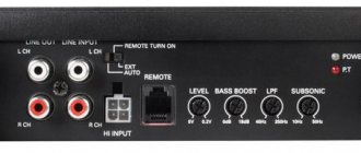
Alternative ways to connect power to the radio
In standard mode, the +12 V supply voltage is supplied to the radio via two wires. Red (signal circuits) is connected to the battery through the ignition switch. The presence or absence of voltage on it is determined by the position of the key.
The yellow wire constantly powers the radio's memory, where all settings are stored. Therefore, it is constantly connected to the positive terminal of the battery directly. When the battery is disconnected from the vehicle's on-board network, the individual settings of the head unit are lost. If there is control voltage at the signal input (red wire), +12 V from the yellow wire is supplied to all blocks of the device.
With a standard power connection, the yellow wire is connected to the battery directly, the red wire is connected through the ignition switch
Some vehicles have a lock position marked ACC. In this mode, the ignition is turned off, but power is supplied to individual devices, including the red wire of the radio.
If there is no ACC mode, the signal wire is connected together with the ignition. In this case, the radio will not be able to work autonomously.
The need for alternative power connection schemes arises when the owner wants to use the radio without turning on the ignition.
Connecting the radio to the battery, bypassing the ignition switch
Connecting the signal (red) power wire directly to the battery positive (in parallel with the yellow one) will ensure that the radio can be turned on at any time, regardless of the position of the key in the ignition switch. To minimize the consequences of short circuits, a separate fuse is included in the circuit.
To minimize the consequences of short circuits, additional fuses are included in the circuit
Connecting a radio via a button
It should be remembered that even when turned off, the radio consumes the energy necessary for memory operation. Current consumption may increase due to leakage if the red power signal wire is constantly connected to the battery, which negatively affects the battery charge level during prolonged periods of inactivity.
The simplest way to eliminate this drawback is to include a button or toggle switch in the circuit, which forcibly breaks the control circuit.
A button or toggle switch allows you to save battery energy when parked
Automatic power off of the radio when the alarm is turned on
More complex ways to save energy when connecting a radio, bypassing the ignition switch, involve the use of relays that respond to the activation of the car's security alarm.
The relay that turns off the power supply to the radio is triggered by a command from the alarm unit
In the diagram above, the relay that turns off the power to the radio is triggered by a command coming from the alarm unit.
There are many other similar schemes. The choice of a particular option depends on the signaling capabilities.
Connecting the radio to the cigarette lighter
Connecting the radio to the cigarette lighter is a type of direct connection to the battery, bypassing the ignition switch.
When connected via a plug, the red and yellow wires are connected together. For long periods of parking, it is better to disconnect the plug from the cigarette lighter. This will save battery power, but will lead to loss of radio settings.
Turning on the head unit via a plug makes it difficult to use the cigarette lighter for its intended purpose. The disadvantage is eliminated by connecting the radio without a plug directly to the wires of the cigarette lighter socket.
The red and yellow wires are connected together to the cigarette lighter power contact
The red and yellow wires of the radio connected together are connected to the red wire of the cigarette lighter, which is supplied with +12 V from the battery. If the head unit is not protected by a built-in fuse, it will not hurt to install an additional one in the power circuit.
Some people are misled by the similar color coding of the radio and cigarette lighter wires. Without thinking, they are connected red to red, yellow to yellow. The radio will turn on anyway, but using the signal lights will disrupt normal operation.
The color markings of the cigarette lighter and radio wires do not match
The head unit consumes a current of about 10 A. A fuse of approximately 15 A is installed in the cigarette lighter circuit. You should check the current values and fuse ratings in the technical documentation before connecting the radio to the cigarette lighter. It is possible that the fuse will not withstand the additional load when the radio and cigarette lighter are turned on together.
Connecting the radio via diodes
Diodes are used when there is no ACC position in the lock so that the radio does not turn off along with the ignition.
The diagram for supplying power to the control input of the radio through diodes is shown in the figure. The yellow main power wire is connected, as usual, to the battery positive. Red (power supply for control circuits) - to the anodes (pluses) of two diodes. The cathode (minus) of one of them is supplied with power through the ignition switch. The cathode of the second is connected to the blue wire - the ANT+ contact of section A of the ISO connector - of the radio or (if available) to the REM signal output to turn on an additional amplifier.
Connecting the radio through diodes allows you to use the device when the car ignition is turned off
After turning on the ignition, +12 V is supplied to the ACC input via the red wire through the lock and the first diode. The radio turns on, voltage appears on the blue ANT+ wire and goes through the second diode to the ACC input.
Now the head unit will remain on even if the ignition is turned off. You can turn off the radio using the built-in controls. To turn it on again, you will need to turn the key in the ignition switch again.
Video: connecting a radio via diodes
Connecting a second (additional) radio
Two radios in a car are not a typical case. As a rule, if the owner is dissatisfied with the quality or capabilities, he changes the head unit to a new one. But when the standard radio does not just reproduce sound, but also performs other important functions for the car, it is difficult to find a full-fledged replacement.
Some owners prefer to solve the problem not by replacing, but by installing an additional device. In this case, it remains possible, for example, while playing music on the new radio, to use the on-board computer and listen to the radio using the old one.
When installing an additional radio, you have to solve two main problems: placing the second device in the cabin near the driver's seat and connecting the speakers independently.
Not all car models have free space in the console for additional devices. Therefore, for the sake of the second radio, they sacrifice low-value cavities: coin drawers, compartments and shelves that are in the area accessible to the driver’s hands. Often you have to adjust holes in plastic parts or cut new ones. Sometimes special podiums are arranged. Unfortunately, an extra device does not always fit organically into the interior of the cabin.
Gallery: examples of placing an additional radio in the car interior
Installed on the dashboard, the additional radio attracts attention
2 DIN seat allows you to place two 1 DIN radios
The radio in the glove compartment is invisible, but it is not very convenient to use
Sometimes to install an additional radio you have to cut out additional holes
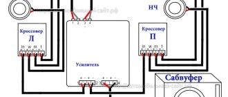
If connecting the power to the second head unit is not fundamentally different from the case with one radio and usually does not cause any special problems, the acoustics require more attention.
Speakers cannot be connected in parallel to both devices at once. This significantly reduces the sound quality and can easily lead to malfunction of the final stages of the radio. Speaker systems must be connected one by one, that is, switch between outputs manually or automatically.
To implement this method in practice, various automotive relays are used. One of the possible schemes with manual control of switching acoustics using a button is shown in the figure.
To alternately connect acoustics to the outputs of two radios, use various car relays
How to properly connect to an electronic device
The concept of an interface as we know it today dates back to the 1960s. More precisely, in 1964, when the company developed its legendary IBM System/360 mainframe. It was then that the main tasks of any interface - physical or virtual - were formulated. They were to provide a standard connection for all devices.
Euro connectors
Initially, only a few types of standard inputs could be made to ensure compatibility between products from different manufacturers. This was a PS/2 port for the keyboard, an LPT port for the printer, and a connector for the PCI card. Nowadays, each type of connection has its own standard interface; this approach greatly simplifies the development and sale of any type of device and allows you to understand their built-in capabilities. Here are descriptions of the main communication elements, first of all, the designation of the button on the radio, which are used on the panels of Pioneer and other car radios.
Types of branded connectors
Description of the buttons on the front panel of the radio for control (decoding)
| Button labels | Button function |
| A.F. | Different RDS frequency, automatic search when reception is poor |
| ALL OFF | Everything is off |
| AMS | Music sensor, works on the principle of playing a number of tracks equal to the number of clicks |
| ANG | Panel adjustment |
| ATA | The radio turns on automatically when you turn off and rewind media tracks |
| A.T.T. | Quickly reduces volume |
| BAND | Selecting a radio receiver |
| BEER | Enabling sound when pressing buttons |
| Blank Skip | Skips pauses longer than 8 seconds |
| BMS | Compensates for low frequencies when dropped due to the main device |
| BTM | Remembers the quality frequency of strong stations |
| CLK ADJ | Adjusts time |
| COLOR | Color |
| DISP | Display activation |
| DNPP | Selecting a CD in the changer |
| DNPS | Entering disc names |
| DSP | Activating the sound processor |
| EJECT | Remove the cassette from the cassette receiver or disc |
| EON | Reception of traffic information |
| FUNCTION | Switches the most used functions |
| INTO SCAN | Plays the recording for 10 seconds to search |
| LOS | Looks for stations, skipping with weak reception |
| LOUD | Tone compensation |
| M.RDM | Disc random playback |
| P.I. | Automatic search |
| PI SOUND | Switching to another frequency |
| PI MUTE | Muffled sound |
| POWER | Shutdown |
| PS | Listening to saved settings |
| PTY | Selecting a genre |
| RDS | Search for a station by metadata |
| RDM | Play disc tracks in any order |
| REG | Switching to the frequency of a radio station with RDS |
| Repeat Play | Replaying a track |
| SCAN | Scanning tracks and playing the beginning |
| SEL | Settings |
| SHUFFLE PLAY | Play available music in random order |
| SYSTEM Q | Tracking sound enhancement factors and showing them on the display |
| TA SEEK | Searching for a station with RDS |
| TC | Calling the tuner when rewinding |
Introduction
But let's start a little from afar... Every young specialist who comes to design begins either by folding drawings, or by reading regulatory documentation, or by drawing “this” according to this example.
In general, normative literature is studied in the course of work and design. It is impossible to read all the normative literature related to your specialty or even a narrower specialization. Moreover, GOST, SNiP and other standards are periodically updated. And each designer has to monitor changes and new requirements of regulatory documents, changes in the lines of electrical equipment manufacturers, and constantly maintain their qualifications at the proper level.
Remember Lewis Carroll in Alice in Wonderland?
This is not my way of whining about “how hard the life of a designer is” or boasting “look, what an interesting job we have.” That's not what we're talking about now. Given such circumstances, designers adopt practical experience from more experienced colleagues; they simply know how to do many things correctly, but do not know why. They work according to the principle “That’s the way it is here.”
Sometimes these are quite basic things. You know how to do it right, but if they ask “Why is this?”, you won’t be able to answer right away, referring at least to the name of the regulatory document.
In this article, I decided to structure the information regarding symbols, sort everything out, and collect everything in one place.
Conditional graphic designations in schemes. Designations for general use (GOST 2.721-74)
A characteristic feature of this scheme is minimal detail. In rooms with normal operating conditions, switches with IP20, maybe up to IP, are installed
Given such circumstances, designers adopt practical experience from more experienced colleagues; they simply know how to do many things correctly, but do not know why.
If there are no points, this is not a connection, but an intersection without an electrical connection. Moreover, there is a difference between fluorescent fluorescent lamps and incandescent lamps. Conceptual drawings are created both single-line and full.
Functions of moving contacts Basic functions can only be performed by fixed contacts. In the diagrams, the power line is depicted passing through the fuse, the resistor is drawn without internal elements. Designation of sockets in the drawings Sockets for single-phase network B are indicated in the diagrams in the form of a semicircle with one or more segments sticking up. If you need to reflect only power lines, it is enough to draw a linear diagram, but to depict all types of circuits with monitoring and control devices you will need a complete one.
Schematic diagram of a radio receiving device. Installation Unlike the above drawings, the installation diagram, in addition to indicating the elements, determines their exact position in two-dimensional space. Conventional graphic symbols of mechanical connections, drives and devices - according to GOST 2.
Installation of electrical wiring and devices in the rooms of the home Graphic symbols in electrical circuits of UGO on functional plans Switching units include contact parts that operate using various mechanisms. Types of contactors The figure shows a two-contact switch.
Basic Basic Images Electrical circuits lead to devices and installations that are equipped with contacts that can break or connect these circuits. Contacts of switching devices consist of moving and fixed contact parts. Sometimes the nominal data is not indicated, in this case the element parameters do not matter; you can select and install the link with the minimum value.
If the standard does not contain the required designation, then it is compiled based on the principle of operation of the element, designations adopted for similar types of devices, devices, machines in compliance with the design principles stipulated by the standard. Image of a circuit breaker in full diagram Contact switching device. Letter designations Along with the UGO, to more accurately determine the name and purpose of the elements, a letter designation is applied to the diagrams. What does a schematic representation of pass-through switches look like? Unlike conventional switches, when using two-key models, another bar is added parallel to the top one. How to read electrical diagrams. Radio components marking designation
Wire
Shaping and Indexing Data: index and extent
You must define the data values and declare the shape of the data before you can run the kernel code. All data is defined to be an array (rectangular), and you can define the array to have any rank (number of dimensions). The data can be any size in any of the dimensions.
index Class
The index Class specifies a location in the or object by encapsulating the offset from the origin in each dimension into one object. When you access a location in the array, you pass an object to the indexing operator, , instead of a list of integer indexes. You can access the elements in each dimension by using the or the .
The following example creates a one-dimensional index that specifies the third element in a one-dimensional object. The index is used to print the third element in the object. The output is 3.
The following example creates a two-dimensional index that specifies the element where the row = 1 and the column = 2 in a two-dimensional object. The first parameter in the constructor is the row component, and the second parameter is the column component. The output is 6.
The following example creates a three-dimensional index that specifies the element where the depth = 0, the row = 1, and the column = 3 in a three-dimensional object. Notice that the first parameter is the depth component, the second parameter is the row component, and the third parameter is the column component. The output is 8.
extent Class
The extent Class specifies the length of the data in each dimension of the or object. You can create an extent and use it to create an or object. You can also retrieve the extent of an existing or object. The following example prints the length of the extent in each dimension of an object.
The following example creates an object that has the same dimensions as the object in the previous example, but this example uses an object instead of using explicit parameters in the constructor.
Fixed resistors
The name of constant resistors is associated with their nominal resistance, which remains unchanged throughout the entire period of operation. They differ depending on the design and materials.
Wire elements consist of metal wires. In some cases, high resistivity alloys may be used. The basis for winding the wire is a ceramic frame. These resistors have high nominal accuracy, but a serious drawback is the presence of a large self-inductance. In the manufacture of film metal resistors, a metal with high resistivity is sprayed onto a ceramic base. Due to their qualities, such elements are most widely used.
The design of carbon fixed resistors can be film or volumetric. In this case, the qualities of graphite as a material with high resistivity are used. There are other resistors, for example, integral ones. They are used in specific integrated circuits where the use of other elements is not possible.
GND on the motherboard circuit in the radio or camera: what is it
Many people are interested in what role GND plays on the motherboard or radio circuit diagram and what it even is. Literally, this is “earth” (from the English word “ground”). Some also use the term to mean "mass" or "minus". In fact, this is a common wire, which is usually white or black. The last option is more common. However, there are other power cord options. For example, blue, green, orange, red and yellow.
It is important to consider the following decodings when repairing the motherboard:
- GND (ground or ground). We are talking about the zero potential point of the microcircuit.
- VEE (Voltage Emitter Emitter) In this case, we mean the minus of the power supply in relation to GND.
- VCC (Voltage Collector Collector is a “voltage collector”). This is just a plus of power in relation to GND.
It is also important to consider that the abbreviation GND may have a slightly different form, for example, DGND, GNDD. This is how digital land will be designated
Analog ground, in turn, can be designated by the abbreviations AGND or GNDA.
- Wire pv-1: technical characteristics, applications and price
To understand the essence, an elementary example should be given. It was necessary to connect an additional fan in the computer case to prevent the unit from overheating. Standard capacity was not enough. Zero fan, black wire was connected to the molex connector wire on the power supply. By the way, it is also made in black. In this case, this is “earth”.
The power supply to the fan itself was yellow. It was connected to a Molex power cable of the same color.
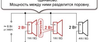
Important! In this case, you should understand simple “arithmetic”:
- When the yellow and black cords are connected, the output is a charge of 12 W.
- The combination of red and black gives only 5 volts.
This is important to consider in order to calculate the required voltage. Otherwise, a short circuit and subsequent malfunction may occur, which is sometimes impossible to eliminate.
By the way, you can also find “POWER” markings on the board and connectors. Here it means nutrition (with a plus sign).
Be sure to pay attention to the sockets with connectors. Sometimes, their design can eliminate incorrect connections
By the way, the computer buttons themselves, for example, reboot and turn on, do not matter at all how you connect them, because the main thing here is the circuit. Pros and cons do not play any role here
Characteristics of mgshv wire
All EA definitions
| Acronym | Definition |
| E.A. | EN Anderen |
| E.A. | Ecole de l'Air |
| E.A. | Eigenmachtig Abwesend |
| E.A. | Ejercito del Er |
| E.A. | Electronic Arts |
| E.A. | Ensiapu |
| E.A. | Enterprise Agreement |
| E.A. | Epreuves d'Artiste |
| E.A. | Employee agent |
| E.A. | Environment Agency |
| E.A. | Alternative Enlazando |
| E.A. | Impact Analysis |
| E.A. | Engineering analysis |
| E.A. | Real estate analysis |
| E.A. | Entreprise Adaptee |
| E.A. | Argentine Army |
| E.A. | Architecture of the ensemble |
| E.A. | Enterprise Architecture |
| E.A. | Entrepreneurs Association |
| E.A. | Endometriosis Association |
| E.A. | Endless centuries |
| E.A. | Everywhere access to |
| E.A. | Eternal Arcadia |
| E.A. | External relations |
| E.A. | External access |
| E.A. | External partner |
| E.A. | External alarm |
| E.A. | Excitation of autoionization |
| E.A. | Educate America |
| E.A. | Eastern Airlines |
| E.A. | Enemy planes |
| E.A. | Elective abortion |
| E.A. | Equipment leveling |
| E.A. | Enemy actions |
| E.A. | Escrowed authenticators |
| E.A. | Jeff Ellis & Associates |
| E.A. | Access to employment |
| E.A. | Exchange Access |
| E.A. | Evangelical Union |
| E.A. | Euclidean algorithm |
| E.A. | European cooperation on accreditation |
| E.A. | Employment benefit |
| E.A. | Registered Agent |
| E.A. | Enrolled actuary |
| E.A. | Environment protection |
| E.A. | Earth Alliance |
| E.A. | Action Land |
| E.A. | Euro area |
| E.A. | Study for aphasia |
| E.A. | Engineering Analysis |
| E.A. | Engineering Authorizations |
| E.A. | Engineering assistant/assistance |
| E.A. | Engineering Ambassadors |
| E.A. | Engineers Australia |
| E.A. | Execution of the agreement |
| E.A. | Executing agency |
| E.A. | Executive agent |
| E.A. | Executive Assistant |
| E.A. | Executable architecture |
| E.A. | Ethan Allen |
| E.A. | Every |
| E.A. | Ever active |
| E.A. | Purpose of engineering |
| E.A. | New adult life |
| E.A. | Areas of interaction |
| E.A. | Exclusion area |
| E.A. | Education Austin |
| E.A. | Environment Australia |
| E.A. | Threat Assessment |
| E.A. | Evaluation authority |
| E.A. | Educator Ambassador |
| E.A. | Transfer area |
| E.A. | Edgewood Square |
| E.A. | Energy Absorption |
| E.A. | Journeyman |
| E.A. | Authority to approve expenses |
| E.A. | Technician assistant |
| E.A. | Technician assistant |
| E.A. | Estimated average |
| E.A. | Equal |
| E.A. | Equal access |
| E.A. | Early Action |
| E.A. | Early availability |
| E.A. | Early access |
| E.A. | Early adoptive parent |
| E.A. | Extended bit address fields |
| E.A. | Extended address |
| E.A. | Extended attribute |
| E.A. | Advanced Mechanism |
| E.A. | Editorial changes |
| E.A. | Private Aviator |
| E.A. | Agreement on the execution of sentences |
| E.A. | Fair adjustment |
| E.A. | Urgent confirmation data |
| E.A. | Automation technology |
| E.A. | Balanced unit |
| E.A. | Approval of appropriations |
| E.A. | Academic Administration |
| E.A. | Implementing agency |
| E.A. | Emergency announcement |
| E.A. | Emergency assistance |
| E.A. | Emergency/enforcement action |
| E.A. | Emergency Events |
| E.A. | Emergency measures |
| E.A. | Emergency powers |
| E.A. | Evolutionary acquisition |
| E.A. | Evolutionary algorithm |
| E.A. | Environmental assessment |
| E.A. | Environmental guarantees |
| E.A. | Environmental audit |
| E.A. | Economic issues |
| E.A. | Economic analysis |
| E.A. | Experimental activities |
| E.A. | Experimental Agent |
| E.A. | Expert |
| E.A. | Electric drive |
| E.A. | Electro absorption |
| E.A. | Electromagnetic anomalies |
| E.A. | Electronics Assembly |
| E.A. | Electronic attacks |
| E.A. | Electronic analysis |
| E.A. | Electric Power Association |
| E.A. | El Alacran |
| E.A. | Emotional romance |
| E.A. | Activation energy |
| E.A. | Alpha energy |
| E.A. | Electron affinity energy |
| E.A. | Encyclopedia Americana |
| E.A. | Episodic ataxia |
| E.A. | Eskilstuna, city, Sweden |
| E.A. | Escrow account |
| E.A. | Effective address |
How to connect the front panel if nothing is clear at all
Look at the photo below:
Here is a good example - the old type of wiring, and also my least favorite. Firstly, nothing is signed, and secondly, the contacts are not arranged in any way, and it is not clear which of them form pairs.
There are two solutions to the problem:
Solution number two:
If there are no instructions, you can use the following method: connect the computer to the electrical network, and then, one by one, briefly close adjacent pairs of contacts with a screwdriver. When the computer starts up during the next short circuit, that pair of contacts is responsible for the Power button. The reset button is located in the same way, only when the computer is running (when the contacts for the Reset button are closed, the computer will reboot)
You will have to search for indicators of hard drive operation and computer operation using the “plug and play” method until they work.
Note: I have been using this method for quite a long time, and have not damaged a single motherboard yet
I advise you to be extremely careful - I am not responsible for lost boards due to your negligence
This concludes my analysis of the front panel connections. There are many more interesting and useful articles planned in the future - subscribe to updates to keep abreast of events on the site.
Types of speakers for cars
Any speakers intended for use inside a car belong to one of the following types:
- broadband - manufacturers usually equip their cars with such speakers at the factory;
- coaxial (coaxial);
- component.
The single speaker of a wideband speaker reproduces the entire spectrum of sound frequencies. This is the cheapest solution, usually used in standard audio systems.
The single speaker of a full-range speaker is capable of reproducing a wide range of sound frequencies
The sound quality will improve if you divide the sound spectrum into several bands and entrust the reproduction of each of them to a separate emitter.
The coaxial speaker has several sound emitters installed in a single housing, which significantly improves sound quality
In a coaxial speaker, several (2–5, usually 3) emitters are installed in a single housing, usually on the same axis, along with filters that highlight the audio frequencies that are optimal for each head.
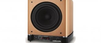
The speakers of the component system are spaced throughout the vehicle
Component speaker systems have the widest range of high-quality reproduction capabilities. In them, as in coaxial speakers, the sound signal is reproduced by several emitters, but each is made in the form of a separate speaker.
Tweeters or tweeters are high-frequency speakers whose task is to reproduce the frequencies of the upper band of the sound spectrum. Conventional tweeters are flat or slightly convex. Horn tweeters are slightly larger than usual ones, as they are equipped with an element that forms a clear polar pattern - a horn.
Tweeters or tweeters are called high-frequency speakers
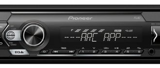
To highlight bands in component systems, crossovers, audio frequency separation filters made in the form of separate blocks, are used.
Crossovers can have from one to four stages: the more stages, the better the sound quality
Component sound systems are the most difficult to install. However, the separation of speakers in space provides the highest quality and surround sound.
What does EA mean in the text?
In sum, EA is an acronym or abbreviation word that is defined in simple language. This page illustrates how EA is used in messaging and chat forums, in addition to social networks such as VK, Instagram, Whatsapp and Snapchat. From the table above, you can view all the meanings of EA: some are educational terms, others are medical terms, and even computer terms. If you know of another definition of EA, please contact us. We will enable it during the next update of our database. Please be aware that some of our acronyms and their definitions are created by our visitors. Therefore, your suggestion for new abbreviations is welcome! As a return, we have translated the acronym of EA to Spanish, French, Chinese, Portuguese, Russian, etc. You can further scroll down and click the language menu to find meanings of EA in other 42 languages.
Accelerating Code: Tiles and Barriers
You can gain additional acceleration by using tiling. Tiling divides the threads into equal rectangular subsets or tiles. You determine the appropriate tile size based on your data set and the algorithm that you are coding. For each thread, you have access to the global location of a data element relative to the whole or and access to the local location relative to the tile. Using the local index value simplifies your code because you don't have to write the code to translate index values from global to local. To use tiling, call the on the compute domain in the method, and use a tiled_index object in the lambda expression.
In typical applications, the elements in a tile are related in some way, and the code has to access and keep track of values across the tile. Use the tile_static Keyword keyword and the to accomplish this. A variable that has the tile_static keyword has a scope across an entire tile, and an instance of the variable is created for each tile. You must handle synchronization of tile-thread access to the variable. The stops execution of the current thread until all the threads in the tile have reached the call to . So you can accumulate values across the tile by using tile_static variables. Then you can finish any computations that require access to all the values.
The following diagram represents a two-dimensional array of sampling data that is arranged in tiles.
The following code example uses the sampling data from the previous diagram. The code replaces each value in the tile by the average of the values in the tile.