Preface
TDA7250 + KT825 , KT827 performed best of all .
In this article I will tell you how to make an amplifier amplifier circuit that is perfect for use in homemade audio equipment.
This publication is the first in a series of articles on making a homemade 4-channel amplifier Phoenix-P400, I talked about it here: DIY AF power amplifier (Phoenix-P400)
Amplifier parameters, a few words about TDA7293
The main criteria by which the ULF circuit was selected for the Phoenix-P400 amplifier:
- Power approximately 100W per channel at 4 Ohm load;
- Power supply: bipolar 2 x 35V (up to 40V);
- Low input impedance;
- Small dimensions;
- High reliability;
- Speed of production;
- High sound quality;
- Low noise level;
- Low cost.
This is not a simple combination of requirements. At first I tried the option based on the TDA7293 chip, but it turned out that this was not what I needed, and here’s why... Over the course of all this time, I had the opportunity to assemble and test different ULF circuits - transistor ones from books and publications of Radio magazine, on various microcircuits...
I would like to say my word about the TDA7293 / TDA7294, because a lot has been written about it on the Internet, and more than once I have seen that the opinion of one person contradicts the opinion of another. Having assembled several clones of an amplifier using these microcircuits, I made some conclusions for myself.
The microcircuits are really quite good, although a lot depends on the successful layout of the printed circuit board (especially the ground lines), good power supply and the quality of the wiring elements.
What immediately pleased me about it was the fairly large power delivered to the load. As for a single-chip integrated amplifier, the low-frequency output power is very good; I would also like to note the very low noise level in the no-signal mode. It is important to take care of good active cooling of the chip, since the chip operates in “boiler” mode.
What I didn’t like about the 7293 amplifier was the low reliability of the microcircuit: out of several purchased microcircuits, at various points of sale, only two were left working! I burned one out by overloading the input, 2 burned out immediately when turned on (it seems like a factory defect), another one burned out for some reason when I turned it on again for the 3rd time, although before that it worked normally and no anomalies were observed... Maybe I was just unlucky.
And now, the main reason why I didn’t want to use modules based on TDA7293 in my project is the “metallic” sound that is noticeable to my ears, there is no softness and richness in it, the mid frequencies are a little dull.
I concluded that this chip is perfect for subwoofers or low-frequency amplifiers that will drone in the trunk of a car or at discos!
I will not touch on the topic of single-chip power amplifiers further; we need something more reliable and of high quality so that it is not so expensive in terms of experiments and errors. Assembling 4 channels of an amplifier using transistors is a good option, but it is quite cumbersome in execution, and it can also be difficult to configure.
So what should you use to assemble if not transistors or integrated circuits? - on both, skillfully combining them! We will assemble a power amplifier using a TDA7250 driver chip with powerful composite Darlington transistors at the output.
Classification of audio power amplifiers
Scope of use
By area of use, amplifiers are divided into household and professional:
- Household amplifiers
are characterized by relatively low price, small size, and an emphasis on minimizing sound distortion. Often they are not separate devices, but are one of the components of other devices in the form of microcircuits. Household amplifiers contain a tone block (equalizer) - a device that adjusts the signal amplitude in a certain frequency range. - Professional amplifiers
focus on increasing the power of sound while maintaining high quality and transmitting it over longer distances. They are used in concert halls, stadiums, recording studios, etc. Most often, such amplifiers are presented in the form of separate devices, and their sizes are standardized (the so-called rack-mount design). This is convenient for transportation and mounting on special telecommunication racks. So, the width of the case should be 17.75 inches (450.85 mm), and the height should be a multiple of 1.75 inches (44.45 mm).
Stereo amplifier Unitra WS-503 ()
Professional sound amplifiers, in turn, are divided into:
- Studio
. These types of devices are used in recording studios and prioritize quality over volume when amplifying sound. Unlike household amplifiers, studio amplifiers do not have a tone block (mixing consoles are used for frequency correction) and the frequency reproduction range is expanded. - Instrumental
. These devices are designed to amplify electric instruments (bass guitars, synthesizers, electric violins, drum machines, etc.). Sometimes instrument audio amplifiers are supplied in a block design (for example, along with a preamplifier, tone control and speakers). They are not used to precisely amplify a signal, but rather to emphasize certain frequencies or add the desired tonal coloration to the musical canvas. - Concert
. As you might guess from the name, such devices are used to amplify sound during concerts, festivals and other musical events. The main requirements for them are reliability and long-term operation at loads close to maximum. Therefore, in concert amplifiers, special attention is paid to various types of protection: from overheating, overvoltage, short circuit and exposure to the external environment.
Keyboard (instrumental) amplifier ()
The cost and quality of professional sound amplifiers are much higher than household ones.
Number of channels
The number of channels supported by audio amplifiers varies on average from one to sixteen. Most amplifiers are two-channel. This means that they can connect up to two speakers in mono or stereo mode. Optimal connection configuration: one channel - one speaker.
Classes
The traditional Institute of Electrical and Electronics Engineers (IEEE) classification uses the letters A, B, C and D to designate the different classes (modes) of audio power amplifiers. There is no single registry of classes for such devices, so other modes are used outside the traditional standard. The same letter in such classifications can denote completely different characteristics, so they are not discussed in the article.
Class A
— broadband single-ended tube amplifiers operate in this mode. Their efficiency is very low (about 20%), but there are practically no high nonlinear distortions.
To class B
includes various transistor amplifiers. Devices in this mode have a relatively low noise level, the efficiency is much higher than in mode A and is 70%. But the sound turns out “dry”, so this mode is unpopular.
Within class AB
engineers combined the advantages of the two classes listed above. At maximum load, mode B is activated, and at normal and minimum load, mode A is activated. The efficiency is about 60%.
Class C
unsuitable for sound reproduction and is most often used in radio transmitter amplifiers due to its high efficiency (from 78.5%).
Class D
is an amplifier with pulse control. This mode was added to the traditional classification in 1955. It is characterized by relatively high efficiency (85%), high-quality sound and small size, which ensures the mobility of devices of this class.
Power and Distortion
One of the important characteristics when choosing an amplifier is its power. It is measured in watts (W) and you can easily find its value in the documentation and even on the packaging. The problem is that manufacturers interpret the very definition of power as such differently. In addition, there are several standards for its definition. Therefore, when choosing an amplifier, confusion often arises.
We also note that the power output by the amplifier directly depends on the resistance of the audio output devices connected to it.
Common definitions of power:
- Maximum sinusoidal power (RMS, Rated Maximum Sinusoidal)
- this parameter shows what level of load the amplifier can withstand for one hour of operation while maintaining further functionality. To measure power, a musical rather than a frequency signal is used. Any possible distortions are not taken into account. - Root Mean Square Power (RMS Power)
- the maximum rms power of the amplifier, during continuous operation with which the distortion remains at the specified values. To measure power, a signal with a frequency of 1 kHz is used, and the nonlinear distortion factor should be equal to 10%. The indicator is used in electrical engineering and is not suitable for assessing the sound qualities of an amplifier, since the human hearing system perceives sound in amplitude, and not root mean square (loud sounds are distinguished better than quiet ones). - Power rating
is one of the most plausible and easy-to-understand specifications: it tests the maximum power an amplifier can operate without exceeding a specified distortion threshold. On the other hand, the threshold values for distortion are specified by the manufacturer himself, which gives him a certain freedom of maneuver. - Peak Music Power Output (PMPO)
refers to the maximum power a device can produce over a short period of time while still operating. There is no single standard for determining this indicator (even the peak interval itself varies from 10 milliseconds to 2 seconds), which makes it meaningless. The indicator is used for advertising purposes only. - DIN
(
DIN 45500, DIN POWER, DIN MUSIC POWER
) is a set of standards for Hi-Fi audio devices that most adequately describe their power. The DIN Power measurement uses a 1 kHz signal to the amplifier input for 10 minutes, with a THD of 1%. DIN Music Power tests use a music signal and a long-term load on the device without the risk of damaging it. The DIN 45500 standard has been transferred with minimal changes to IEC 60581 and GOST 24388-88.
LF power amplifier circuit based on TDA7250 chip
The TDA7250 chip in a DIP-20 package is a reliable stereo driver for Darlington transistors (high-gain composite transistors), on the basis of which you can build a high-quality two-channel stereo UMZCH.
The output power of such an amplifier can reach or even exceed 100 W per channel with a load resistance of 4 Ohms; it depends on the type of transistors used and the supply voltage of the circuit.
After assembling a copy of such an amplifier and the first tests, I was pleasantly surprised by the sound quality, power and how the music produced by this microcircuit “came to life” in combination with transistors KT825, KT827. Very small details began to be heard in the compositions, the instruments sounded rich and “light”.
You can burn this chip in several ways:
- Reversing the polarity of power lines;
- Exceeding the maximum permissible supply voltage ±45V;
- Input overload;
- High static voltage.
Rice. 1. TDA7250 microcircuit in a DIP-20 package, appearance.
Datasheet for the TDA7250 chip - (135 KB).
Just in case, I purchased 4 microcircuits at once, each of which has 2 amplification channels. The microcircuits were purchased from an online store at a price of approximately $2 per piece. At the market they wanted more than $5 for such a chip! The scheme according to which my version was assembled does not differ much from the one shown in the datasheet:
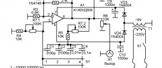
Rice. 2. Circuit of a stereo low-frequency amplifier based on the TDA7250 microcircuit and transistors KT825, KT827.
Also, for a better understanding of what is happening in the microcircuit, it would not be amiss to provide here its block diagram from the documentation:
Rice. 3. Block diagram of the TDA7250 integrated amplifier (block diagram).
On some foreign sites, in amplifier circuits based on this microcircuit, you can find an additional 100K resistor installed between resistor R9 and -Vs (in the chain for setting the quiescent current of the output stages - pin 3).
If you study the block diagram of the TDA7250, you can understand that this resistor is not needed there. But in the chain that is connected to pin 8, a 100K resistor is necessary, since inside the microcircuit this pin is connected to the input of the operational amplifier and an external 100K resistor sets some required bias voltage.
Therefore, the external circuits connected to pins 3 and 8 of the microcircuit should not be identical - this is not an error in the datasheet, as someone might think.
For this UMZCH circuit, a homemade bipolar power supply of +/- 36V was assembled, with capacitances of 20,000 μF in each arm (+Vs and -Vs).
Three ULF circuits for beginners
After mastering the basics of electronics, the novice radio amateur is ready to solder his first electronic designs. Audio power amplifiers are typically the most repeatable designs. There are quite a lot of schemes, each with its own parameters and design. This article will discuss several simple and fully working amplifier circuits that can be successfully repeated by any radio amateur. The article does not use complex terms and calculations; everything is simplified as much as possible so that no additional questions arise.
Let's start with a more powerful circuit. So, the first circuit is made on the well-known TDA2003 microcircuit. This is a mono amplifier with an output power of up to 7 watts into a 4 ohm load. I want to say that the standard circuit for connecting this microcircuit contains a small number of components, but a couple of years ago I came up with a different circuit on this microcircuit. In this circuit, the number of components is reduced to a minimum, but the amplifier has not lost its sound parameters. After developing this circuit, I began making all my amplifiers for low-power speakers using this circuit.
The circuit of the presented amplifier has a wide range of reproducible frequencies, a supply voltage range from 4.5 to 18 volts (typical 12-14 volts). The microcircuit is installed on a small heat sink, since the maximum power reaches up to 10 Watts.
The microcircuit is capable of operating at a load of 2 ohms, which means that 2 heads with a resistance of 4 ohms can be connected to the amplifier output. The input capacitor can be replaced with any other one, with a capacity from 0.01 to 4.7 μF (preferably from 0.1 to 0.47 μF), you can use both film and ceramic capacitors. It is advisable not to replace all other components.
Volume control from 10 to 47 kOhm. The output power of the microcircuit allows it to be used in low-power speakers for PCs. It is very convenient to use the chip for stand-alone speakers for a mobile phone, etc. The amplifier works immediately after switching on and does not require additional adjustment. It is recommended to additionally connect the power supply minus to the heat sink. It is advisable to use all electrolytic capacitors at 25 Volts.
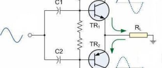
The second circuit is assembled using low-power transistors and is more suitable as a headphone amplifier.
This is probably the highest quality circuit of its kind, the sound is clear, you can feel the entire frequency spectrum. With good headphones, it feels like you have a full-fledged subwoofer.
The amplifier is assembled with only 3 reverse conduction transistors; as the cheapest option, transistors of the KT315 series were used, but their choice is quite wide.
The amplifier can operate at a low-impedance load, up to 4 ohms, which makes it possible to use the circuit to amplify the signal of a player, radio, etc. A 9-volt Krona battery is used as a power source. The final stage also uses KT315 transistors. To increase the output power, you can use KT815 transistors, but then you will have to increase the supply voltage to 12 volts. In this case, the amplifier power will reach up to 1 Watt. The output capacitor can have a capacity from 220 to 2200 µF. The transistors in this circuit do not heat up, therefore, no cooling is needed. If you use larger output transistors, you may need small heat sinks for each transistor.
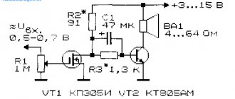
And finally - the third scheme. An equally simple, but proven version of the amplifier structure is presented. The amplifier is capable of operating from reduced voltage to 5 volts, in which case the PA output power will be no more than 0.5 W, and the maximum power with a 12 volt supply reaches up to 2 Watts.
The output stage of the amplifier is built on a domestic complementary pair. The amplifier is regulated by selecting resistor R2. To do this, it is advisable to use a 1 kOhm trimmer. Slowly rotate the regulator until the quiescent current of the output stage is 2-5 mA.
The amplifier does not have high input sensitivity, so it is advisable to use a pre-amplifier before the input.
The diode plays a significant role in the circuit; it is here to stabilize the mode of the output stage. The output stage transistors can be replaced with any complementary pair of corresponding parameters, for example KT816/817. The amplifier can power low-power stand-alone speakers with a load resistance of 6-8 ohms.
List of radioelements
| Designation | Type | Denomination | Quantity | Note | Shop | My notepad |
| Amplifier on TDA2003 chip | ||||||
| Audio amplifier | TDA2003 | 1 | Search in the Otron store | To notepad | ||
| C1 | Electrolytic capacitor | 47 uF x 25V | 1 | Search in the Otron store | To notepad | |
| C2 | Capacitor | 100 nF | 1 | Film | Search in the Otron store | To notepad |
| C3 | Electrolytic capacitor | 1 uF x 25V | 1 | Search in the Otron store | To notepad | |
| C5 | Electrolytic capacitor | 470 uF x 16V | 1 | Search in the Otron store | To notepad | |
| R1 | Resistor | 100 Ohm | 1 | Search in the Otron store | To notepad | |
| R2 | Variable resistor | 50 kOhm | 1 | From 10 kOhm to 50 kOhm | Search in the Otron store | To notepad |
| Ls1 | Dynamic head | 2-4 Ohm | 1 | Search in the Otron store | To notepad | |
| Transistor amplifier circuit No. 2 | ||||||
| VT1-VT3 | Bipolar transistor | KT315A | 3 | Search in the Otron store | To notepad | |
| C1 | Electrolytic capacitor | 1 uF x 16V | 1 | Search in the Otron store | To notepad | |
| C2, C3 | Electrolytic capacitor | 1000 uF x 16V | 2 | Search in the Otron store | To notepad | |
| R1, R2 | Resistor | 100 kOhm | 2 | Search in the Otron store | To notepad | |
| R3 | Resistor | 47 kOhm | 1 | Search in the Otron store | To notepad | |
| R4 | Resistor | 1 kOhm | 1 | Search in the Otron store | To notepad | |
| R5 | Variable resistor | 50 kOhm | 1 | Search in the Otron store | To notepad | |
| R6 | Resistor | 3 kOhm | 1 | Search in the Otron store | To notepad | |
| Dynamic head | 2-4 Ohm | 1 | Search in the Otron store | To notepad | ||
| Transistor amplifier circuit No. 3 | ||||||
| VT2 | Bipolar transistor | KT315A | 1 | Search in the Otron store | To notepad | |
| VT3 | Bipolar transistor | KT361A | 1 | Search in the Otron store | To notepad | |
| VT4 | Bipolar transistor | KT815A | 1 | Search in the Otron store | To notepad | |
| VT5 | Bipolar transistor | KT816A | 1 | Search in the Otron store | To notepad | |
| VD1 | Diode | D18 | 1 | Or any low power | Search in the Otron store | To notepad |
| C1, C2, C5 | Electrolytic capacitor | 10 uF x 16V | 3 | Search in the Otron store | To notepad | |
| C4 | Electrolytic capacitor | 470 uF x 16V | 1 | Search in the Otron store | To notepad | |
| R1 | Variable resistor | 50 kOhm | 1 | Search in the Otron store | To notepad | |
| R2 | Resistor | 100 kOhm | 1 | Search in the Otron store | To notepad | |
| R3 | Resistor | 3 kOhm | 1 | Search in the Otron store | To notepad | |
| R4 | Resistor | 100 Ohm | 1 | Search in the Otron store | To notepad | |
| R5 | Resistor | 150 Ohm | 1 | Search in the Otron store | To notepad | |
| R6, R7 | Resistor | 1 kOhm | 2 | Search in the Otron store | To notepad | |
| Dynamic head | 6-8 Ohm | 1 | Search in the Otron store | To notepad | ||
| Add all | ||||||
Attached files:
- 3amps.rar (21 Kb)
Tags:
- ULF
- Sprint-Layout
Power Amplifier Parts
I’ll tell you more about the features of the amplifier parts. List of radio components for circuit assembly:
| Name | Quantity, pcs | Note |
| TDA7250 | 1 | |
| KT825 | 2 | |
| KT827 | 2 | |
| 1.5 kOhm | 2 | |
| 390 Ohm | 4 | |
| 33 Ohm | 4 | power 0.5W |
| 0.15 Ohm | 4 | power 5W |
| 22 kOhm | 3 | |
| 560 Ohm | 2 | |
| 100 kOhm | 3 | |
| 12 ohm | 2 | power 1W |
| 10 ohm | 2 | power 0.5W |
| 2.7 kOhm | 2 | |
| 100 Ohm | 1 | |
| 10 kOhm | 1 | |
| 100 µF | 4 | electrolytic |
| 2.2 µF | 2 | mica or film |
| 2.2 µF | 1 | electrolytic |
| 2.2 nF | 2 | |
| 1 µF | 2 | mica or film |
| 22 µF | 2 | electrolytic |
| 100 pF | 2 | |
| 100 nF | 2 | |
| 150 pF | 8 | |
| 4.7 µF | 2 | electrolytic |
| 0.1 µF | 2 | mica or film |
| 30 pf | 2 |
The inductor coils at the output of the UMZCH are wound on a frame with a diameter of 10 mm and contain 40 turns of enameled copper wire with a diameter of 0.8-1 mm in two layers (20 turns per layer). To prevent the coils from falling apart, they can be fastened with fusible silicone or glue.
Capacitors C22, C23, C4, C3, C1, C2 must be designed for a voltage of 63V, the remaining electrolytes - for a voltage of 25V or more. Input capacitors C6 and C5 are non-polar, film or mica.
Resistors R16-R19 must be rated for a power of at least 5W. In my case, miniature cement resistors were used.
Resistances R20-R23, as well as RL, can be installed with a power of 0.5 W. Resistors Rx - with a power of at least 1W. All other resistances in the circuit can be set to a power of 0.25W.
It is better to select pairs of transistors KT827 + KT825 with the closest parameters, for example:
- KT827A (Uke=100V, h21E>750, Pk=125W) + KT825G (Uke=70V, h21E>750, Pk=125W);
- KT827B (Uke=80V, h21E>750, Pk=125W) + KT825B (Uke=60V, h21E>750, Pk=160W);
- KT827V (Uke=60V, h21E>750, Pk=125W) + KT825B (Uke=60V, h21E>750, Pk=160W);
- KT827V (Uke=60V, h21E>750, Pk=125W) + KT825G (Uke=70V, h21E>750, Pk=125W).
Depending on the letter at the end of the marking for KT827 transistors, only the voltages Uke and Ube change, the rest of the parameters are identical. But KT825 transistors with different letter suffixes already differ in many parameters.
Rice. 4. Pinout of powerful transistors KT825, KT827 and TIP142, TIP147.
It is advisable to check the transistors used in the amplifier circuit for serviceability. Darlington transistors KT825, KT827, TIP142, TIP147 and others with a high gain contain two transistors, a couple of resistances and a diode inside, so a regular test with a multimeter may not be enough here.
To test each of the transistors, you can assemble a simple circuit with an LED:
Rice. 5. Scheme for testing transistors of the PNP and NPN structure for operability in the key mode.
In each of the circuits, when the button is pressed, the LED should light up. Power can be taken from +5V to +12V.
Rice. 6. An example of testing the performance of the KT825 transistor, PNP structure.
Each pair of output transistors must be installed on radiators, since already at an average ULF output power their heating will be quite noticeable.
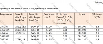
The datasheet for the TDA7250 chip shows the recommended pairs of transistors and the power that can be extracted using them in this amplifier:
| At 4 ohm load | ||||
| ULF power | 30 W | +50 W | +90 W | +130 W |
| Transistors | BDW93, BDW94A | BDW93, BDW94B | BDV64, BDV65B | MJ11013, MJ11014 |
| Housings | TO-220 | TO-220 | SOT-93 | TO-204 (TO-3) |
| At 8 ohm load | ||||
| ULF power | 15 W | +30 W | +50 W | +70 W |
| Transistors | BDX53, BDX54A | BDX53, BDX54B | BDW93, BDW94B | TIP142, TIP147 |
| Housings | TO-220 | TO-220 | TO-220 | TO-247 |
Mounting transistors KT825, KT827 (TO-3 housing)
Particular attention should be paid to the installation of output transistors. A collector is connected to the housing of transistors KT827, KT825, so if the housings of two transistors in one channel are accidentally or intentionally shorted, you will get a short circuit in the power supply!
Rice. 7. Transistors KT827 and KT825 are prepared for installation on radiators.
If the transistors are planned to be mounted on one common radiator, then their cases must be insulated from the radiator through mica gaskets, having previously coated them on both sides with thermal paste to improve heat transfer.
Rice. 8. Radiators that I used for transistors KT827 and KT825.
In order not to describe for a long time how to install isolated transistors on radiators, I will give a simple drawing that shows everything in detail:
Rice. 9. Insulated mounting of transistors KT825 and KT827 on radiators.
Printed circuit board
Now I'll tell you about the printed circuit board. It will not be difficult to separate it, since the circuit is almost completely symmetrical for each channel. You need to try to distance the input and output circuits from each other as much as possible - this will prevent self-excitation, a lot of interference, and protect you from unnecessary problems.
Fiberglass can be taken with a thickness of 1 to 2 millimeters; in principle, the board does not need special strength. After etching the tracks, you need to tin them well with solder and rosin (or flux), do not ignore this step - it is very important!
I laid out the tracks for the printed circuit board manually, on a sheet of checkered paper using a simple pencil. This is what I have been doing since the times when one could only dream about SprintLayout and LUT technology. Here is a scanned stencil of the printed circuit board design for the ULF:
Rice. 10. Amplifier printed circuit board and arrangement of components on it (click to open full size).
Capacitors C21, C3, C20, C4 are not on the hand-drawn board, they are needed to filter the power supply voltage, I installed them in the power supply itself.
Thanks to Alexander for laying out the printed circuit board in the Sprint Layout program!
Rice. 11. Printed circuit board for UMZCH on the TDA7250 chip from Alexander.
In one of my articles, I told you how to make this printed circuit board using the LUT method.
I present here printed circuit boards, including those mentioned in the comments to the publication:
- Download the printed circuit board in *.lay format from Alexander - (84 KB).
- Printed circuit board in *.lay format from Vitaly Novak - (35 KB);
- Printed circuit board in *.lay6 format from Fivist - (50Kb);
- Printed circuit board in *.lay6 format from Patunum - (160 KB).
About file formats:
- *.lay - files for the Sprint Layout program versions 5.0 (2006) and 6.0 (2013);
- *.lay6 - files for Sprint Layout, which can only be opened in the program starting from version 6.
As for the connecting wires for power supply and at the output of the UMZCH circuit, they should be as short as possible and with a cross-section of at least 1.5 mm. In this case, the shorter the length and greater the thickness of the conductors, the less current loss and interference in the power amplification circuit.
The result was 4 amplification channels on two small strips:
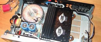
Rice. 12. Photos of finished UMZCH boards for four power amplification channels.
Integral ULF
A low-frequency power amplifier is an electronic device that is designed to amplify a low-frequency (LF) signal and then feed it to speaker systems. Often homemade integrated low-frequency power amplifiers are assembled on powerful microcircuits, since they require a minimum of external components and are very easy to set up.
The section contains schematic diagrams of low-frequency power amplifiers based on powerful microcircuits, as well as on the basis of integrated circuits - drivers for output transistors. Using specialized integrated circuits, you can assemble a power amplifier of various configurations:
- Stereo - two power amplification channels;
- Quad — four channels of power amplification;
- 2+1 - subwoofer and two satellites;
- 5+1 - subwoofer and five satellites;
- and others.
If you need a large output power of a low-frequency amplifier (for example, for a subwoofer channel - 200 Watt), then bridge circuits for connecting microcircuits or in parallel are often used.
Here you will find circuits of homemade UMZCHs of varying complexity for external and integrated speaker systems, circuits of simple amplifiers for headphones and miniature household appliances (players, MP3, voice recorders, toys, etc.).
Audio power amplifier circuit based on OPA541 chip (60W)
We can say that such a tradition has already developed: if you need a powerful UMZCH with a minimum set of wiring and good parameters, it is made on a TDA or LM chip. Tradition is tradition, but there are other options, although not as proven and proven... The experience with the UMZCH on the OPA541 chip is still interesting...
1 1010 0
Power amplifier on LM3876, LM3886 chip (40-100 W)
Diagram and description of a homemade power amplifier based on the LM3876, LM3886 microcircuit from NS (National Semiconductor). Amplifier parameters: 1. Nominal input signal level... 1V. 2. Output power at a load of 8 Ohms at a THD of no more than 0.1%..... 40W...
2 1094 0
Powerful UMZCH on TDA7294 chip, printed circuit board (50W at 8 Ohm)
Those who are designing an amplifier for an audio system or DVD player, of course, want to achieve the best results with minimal labor costs. The UMZCH on the TDA7294 chip is in this sense exactly what you need. Here are nine reasons in favor of the UMZCH on the TDA7294: 1 Output power...
0 1138 0
Homemade sound amplifier for a tablet or smartphone using a TDA1554Q chip
Nowadays, many motorists use tablet computers in their cars. This is very convenient, because a tablet is also a means of mobile audio and video communication, it is a navigator, with its help you can quickly find the necessary information on the Internet. In addition, the tablet can work as a radio receiver, like...
3 1399 0
Two-channel audio amplifier on TDA7496L chip (2 W at 8 Ohm)
Integrated circuit type TDA7496L manufactured by SGT-Thomson Microelectronics is a two-channel audio amplifier with an output power in each channel of up to 2 W at a load of 8 ohms. Maximum power dissipation 6 W. supply voltage unipolar...
0 2149 0
A simple stereo bass amplifier for a computer based on the K174UN20 chip
The amplifier is stereophonic, made on a Soviet-made K174UN20 microcircuit. The microcircuit contains two ULFs, the circuit design is similar to two K174UN14 type microcircuits, but of lower power and in a DIP16 type package, but with two radiator plates instead of leads...
1 1521 0
Audio power amplifier with tone control (LM741, LM1875)
The amplifier develops an output power of up to 25W per channel and can operate speaker systems with impedance from 3 to 10 ohms. With an output power of 16W per channel and speaker systems with a resistance of 6 Ohms, the THD at a frequency of 1 kHz does not exceed 0.03%. There is a tone control for low and high...
1 3276 0
A simple stereo amplifier on the TDA2005 chip with tone control
The TDA2005 microcircuit is outdated and has not been produced for a long time, but it still remains one of the most inexpensive and widely available integrated UMZCH. A relatively small number of attachments, combined with quite good electrical characteristics, the presence of output overload protection...
1 1482 0
Stereo sound amplifier based on TDA2050 chips with HF and LF controls
This is a simple full ULF on two TDA2050 microcircuits, powered by a switching power supply for halogen lamps (output alternating voltage 12V, power 75W). Amplifier characteristics: 1. Maximum output power into a 4 Ohm load 2x12W ...
2 3571 0
A simple audio signal amplifier on a TDA1010A chip (7 Watt)
The TDA1010A chip is a ULF IC for televisions and other electronic equipment. The peculiarity of this microcircuit is that it contains both an AF power amplifier and a pre-amplifier. Moreover, the output of the pre-amplifier and the input of the power amplifier are connected to different...
1 1323 0
1 …
Setting up the amplifier
A correctly assembled circuit made from serviceable parts begins to work immediately. Before connecting the structure to the power source, you need to carefully inspect the printed circuit board for any short circuits, and also remove excess rosin using a piece of cotton wool soaked in a solvent.
I also recommend installing a 1A fuse in series with each of the power lines (+Vs, -Vs). This will help protect some components of the circuit in case of some error.
I recommend connecting speaker systems to the circuit when you first turn it on and during experiments using resistors with a resistance of 300-400 Ohms, this will save the speakers from damage if something goes wrong.
It is advisable to connect a volume control to the input - one dual variable resistor or two separately. Before turning on the UMZCH, we put the switch of the resistor(s) in the left extreme position, as in the diagram (minimum volume), then by connecting the signal source to the UMZCH and applying power to the circuit, you can smoothly increase the volume, observing how the assembled amplifier behaves.
Rice. 13. Schematic illustration of connecting variable resistors as volume controls for ULF.
Variable resistors can be used with any resistance from 47 KOhm to 200 KOhm. When using two variable resistors, it is desirable that their resistances be the same.
So, let's check the performance of the amplifier at low volume. If everything is fine with the circuit, then the fuses on the power lines can be replaced with more powerful ones (2-3 Amperes); additional protection during operation of the UMZCH will not hurt.
The quiescent current of the output transistors can be measured by connecting an ammeter or multimeter in current measurement mode (10-20A) to the collector gap of each transistor. The amplifier inputs must be connected to common ground (complete absence of input signal), and speakers must be connected to the amplifier outputs.
Rice. 14. Circuit diagram for connecting an ammeter to measure the quiescent current of the output transistors of an audio power amplifier.
The quiescent current of the transistors in my UMZCH using KT825+KT827 is approximately 100mA (0.1A).
When setting up an amplifier, power fuses can also be replaced with powerful incandescent lamps. If one of the amplifier channels behaves inappropriately (hum, noise, overheating of transistors), then it is possible that the problem lies in the long conductors going to the transistors; try reducing the length of these conductors.
Safety measures when first turned on (power lamps, speaker protection), experiments with different transistors and other useful information on this amplifier are also described in detail in the article “Repair of the Radiotekhnika U-101 amplifier, UMZCH module on the TDA7250 chip.”
How to choose an audio power amplifier
When purchasing both a household and professional sound amplifier, adhere to the following rule: the amplifier should be selected together with the speaker system. This is necessary to match the power of the devices - a weak amplifier will not be able to operate at maximum load for a long time, and a too powerful one will damage the speakers. Also, when calculating the required power, always allow for some reserve - it is better not to operate the device at the limit of its capabilities.
For home use, you should first think about whether you really need an amplifier? Most likely, it is already built into the sound reproduction device and its characteristics are more than enough for the average user. If you are a connoisseur with special requirements for sound, pay attention to tube amplifiers.
When choosing a professional device, decide on the conditions of use - in what place do you need to amplify the sound, under what conditions and what kind of sound? Sound amplifiers for emergency warning systems operate on completely different principles than sound amplifiers in recording studios.
What buyers also often miss is that the performance of an amplifier is not measured solely by power. We should not forget about the noise level, weight and dimensions of the amplifier, materials and workmanship.