According to the technical specifications, the TDA7388 chip is a four-way class AB audio amplifier with a maximum output power of up to 41 W per channel with a load of 4 ohms. Developed specifically for car radios by ST Microelectronics. The device allows you to create audio systems with a minimum set of electronic components. Ready-made modules based on it and constructors for do-it-yourself assembly are widely available on sale.
The TDA7388 is sometimes called a sound processor. It is positioned on the market as a budget version. The price of the device in Russia starts from 200 rubles. Quite often found in standard car audio systems, various radios and radios. Very popular among manufacturers of inexpensive equipment. But today it is difficult to surprise the spoiled consumer with its sound quality. Therefore, many people specifically buy such systems and then solder the amplifier to a more powerful and more expensive analogue like the TDA7850.
Technical specifications
According to the datasheet, the TDA7833 delivers up to 41 W of power (PO) to each of the four channels, into a load of up to 4 ohms. It is worth considering that this is the maximum possible value declared by the manufacturer for a maximum voltage of 18 V, with the highest non-linear distortion (THD). In the best case, when using an amplifier from the car's power supply (12-14 V), you can drive good speakers up to 15-20 clean, undistorted watts.
Maximum
Here is a list of the maximum possible parameter values for the TDA7833:
- supply voltage: operating (VCC) 10…18 V; maximum (VCC (pk)) up to 50 V;
- output current (IO): repeating (D=10%, f=10 Hz) up to 4.5 A; non-repetitive (t=100 μs) up to 5 A;
- dissipated power (Ptot) up to 80 W, at TC up to 70 oC;
- temperature: crystal (TC) up to + 150 oC; storage (TSTG) -55 … +150 oC.
Electrical
The table of basic electrical parameters is shown in the figure below. They are obtained under the following test conditions: V CC = 14.4 V, RL = 4 ohms, R g = 600 ohms, f = 1 kHz, TA up to 25 °C unless otherwise stated.
Jabot report
The bosses are on vacation, there is anarchy at work. Friday. All projects and routine are completed. You can devote a couple of hours to personal automotive matters.
I decided not to write a report, I decided to do an abstract. Or scientific research work, analyzing posts and comments and making a large post about this modification.
1) Articles used and their authors.
al13l www.drive2.ru/l/1307802/ — It was this article that dispelled all doubts. Mordvin113 www.drive2.ru/l/6667614/ — This article helped a lot Serhioos www.drive2.ru/l/4993448/ — This article also helped a lot
2) Description of microcircuits comparison
DataSheet_TDA7385H DataSheet_TDA7560
2.1) Main characteristics of TDA7385
TDA7385 - Output power 4 * 35 W - Low noise level - Low distortion level - Sound mute function - Shutdown when overheated - Anti-static electricity protection - Standby function - Overload protection
The rest I don’t know how to translate into Russian
2.2) Main characteristics TDA7560
TDA7560 - Output power 4*50 W - Low noise - Hi-fi distortion level
-Too lazy to translate the rest. But the gist of it is that this microcircuit, compared to a regular one, is cool, like Chuck Norris (So it’s written in the Datasheet). If you want, run it through a translator and it will be more or less clear.
3) Nuances of re-soldering
Unscrews the 4 TORX bolts from the top and removes the cover. We take out the CD block from the case (nothing holds it anymore) and disconnect the cable on the red connector.
Unscrew the two TORX bolts from the bottom. Remove the cover. We see the microcircuit under the radiator. We drill out 4 rivets, drill out the bottom left one carefully so as not to break through the capacitor. If you have a smarter chip, for vertical mounting. then you will have to bend the legs for horizontal installation. It’s crooked, but the main thing is the result. How to unsolder the old chip? How to unsolder the old chip?
1) Using wire cutters we bite out the old microcircuit 2) Solder one leg at a time 3) Clean the mounting holes 3.1) Using vacuum solder suction. (ru.aliexpress.com/item/1p…c-Device/32688654770.html) 3.2) Or we just heat up the soldering iron and poke it with a toothpick, simple and effective.
We insert a new microcircuit. We fix and solder. How convenient and how convenient. Apply a thin layer of any thermal paste to both surfaces. We install the radiator. and secure with 2-3 screws and nuts. But let's not delay! We put the bottom cover on, screw in the two bottom screws that attract the radiator to the chip. And only then we tighten the remaining screws.
4) Difficulties
— When drilling a radiator, there is a chance of breaking through the capacitor, it is better to place a steel plate there when you drill.
— When desoldering an old microcircuit and cleaning the holes, there is a chance of overheating the board and tearing out the contact sleeve. — After installing a new microcircuit, it is necessary to inspect the contacts under a microscope and ring it with a tester. so that there is no short circuit. — We read a very competent comment from andygl “Stunning! I stirred up a hornet’s nest! Now on the topic, replacing the amplifier chip will increase the power, but most importantly the sound quality. And now a very important note! Anyone who wants to go this route, before replacing, make sure that according to the circuit you have the diagnostic pin is not used, pin 25 if it is involved in the circuit of your device when replacing you will hear silence. See the TDA 7384, TDA7386, TDA7560 line, this pin has a different meaning, for TDA7381, TDA7382, TDA7383, TDA7385 this pin works and gives a diagnostic signal for sound resolution. I didn’t look at the entire line, see the pdf and the diagram of your device. I already explained to the person who replaced the microcircuit that the microcircuit was in order, he thought that he bought a defective one.”
—
In general, we read all the comments in the articles, the links to which I gave at the beginning.
5) What has changed? I took a CD with classical music and a Collection of Rock Music, listened to several songs at a volume of 10-15-20-25-30. I sketched out a sign. The wheezing distortion started to appear for me at 22, and by 30 it was no longer pleasant to listen to. The settings were BASS +2, the rest were Zeros. After soldering I immediately went to test it. On classical music, distortion was absent even at 32. On rock music, it appeared at 30, if you pay attention, and then only in some songs. At 32 there was slight distortion in the mid frequencies. At the same time, I immediately lowered BASS to +1. On the tested songs, low frequencies became distortion-free. When listening to MP3 through the YATOR CD changer. There was no distortion on all tracks. Perhaps this is due to the fact that he generally plays quieter.
PS This article is for informational purposes only and does not call for any action.
Issue price: 400
Peculiarities
The microcircuit has built-in protective functions that protect it from overheating, overvoltage, overcurrent and short circuit. Equipped with silence (Mute) and sleep (St-By) modes. These functions are turned on when a voltage of more than 3.5 V is applied to the corresponding contacts (described above), and are turned off when it drops to 1.5 V. For them to work continuously, it is possible to short the corresponding pins of the microcircuit to the positive power supply.
The complementary PNP/NPN output circuit of the TDA 7388 makes it possible to achieve supply voltage values without the use of booster capacitors. Unfortunately, this microcircuit cannot be used with low-impedance loads (from 2 ohms) of premium class acoustics.
Using the TDA7388 chip
For beginners and people who do not want to spend a lot of time making an amplifier, it is recommended to take a ready-made microcircuit to create a gadget. This will make it possible to customize the equipment to suit your needs.
Characteristics
The manufacturer indicates that the voltage of this amplifier varies from 10 to 18 V. The latter indicator is more suitable; in some places jumps up to 50 volts are possible. It is easy to select a power supply for these indicators, and the designed circuit will work stably. Field-effect transistors are used at the output stage, this is also a plus.
When using a microcircuit, the amplifier will be class AB; it operates with frequencies up to 20 thousand Hz. There is protection against overheating and short circuit during operation. The device is simpler to manufacture than its analogues, so components are easy to find.
Assembly
To create an amplifier you will need a printed circuit board with dimensions of 35*70 mm. Capacitors take up to 25 W; film and electrolytic ones are suitable. If problems arise with the TDA7388 circuit, then it is replaced with the TDA7560, they are considered the same. The cascade operates in bridge mode, so separate capacitors are not used.
Immediately after assembly, the device will work; no additional parts are required. During installation of the structure, it is worth considering that the MUTE and ST-BY pins are shorted to positive; they are turned on when the bus is disconnected. When choosing a power supply, take into account that the maximum current should not be higher than 15 A.
The disadvantage of a homemade amplifier is the overall radiator, at least 50 square cm. Reducing the size is only possible when installing a cooling radiator.
Analogs
Different microcircuits are used to make an amplifier. We list the parts that are also suitable for installation:
- TDA 7850. The best analogue for car acoustics. It has a high sound class and does not distort the sound. Minimizes parasitic noise, guarantees clarity and bassiness of music.
- TDA 7560. The output power is lower here, but this part costs less. The chip was first used for car radios.
- TDA 7851. It has similar characteristics to the first analogue, but the output power is reduced. Sound is transmitted through the part perfectly; there are several protective mechanisms against burnout.
Making your own amplifier will allow you to save money and determine the criteria for the device yourself, rather than choosing from what is available in car stores. However, we should not forget about the risks that depend on the quality of the components and the assembly itself. Weigh all the factors before deciding to purchase or install the device yourself.
Analogs
In search of better sound, audiophiles are looking for an analogue for the TDA7833. It is believed that this is due to the lack of clean high frequencies and “soft bass” in this microcircuit. It can be replaced in acoustic systems, without changing the binding components, with better parameters and at the same time more expensive: TDA7560, TDA7850, TDA7851. Also suitable as a replacement: pal007, tda7381, tda7384, YD7388. In this case, it is necessary to check that the pinout of these devices is identical.
How to replace tda7388 with tda7850 in Chinese radios is presented in the following video.
DataSheet for the tda7388 amplifier in pdf can be downloaded from the link.
Where it all started
I put up with this for 4 years. One day in the spring of 2022, a friend and I were discussing car audio and he boasted that he had ordered an Android radio from China; it cost him 15,000 rubles. The sound is much better, there is navigation, it looks great. I was very inspired by this. And I also decided to see what China could offer for my car.
It turned out that there are plenty of options. Several appearance designs, different characteristics, different screen sizes, different fillings. After a week of searching, I decided on the model. I had some money saved up and I placed an order.
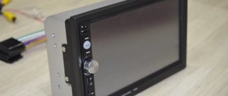
I will not dwell on the characteristics in detail. At that time, it was the most powerful radio with Android 6 on board, 2 GB of RAM and a 4G modem. Externally, the radio looked very stylish. But most of all I was interested in the sound quality and speed. There was no way to check it at home, I had to wait for the weekend and plan a trip to the garage to install the radio in the car. Because I really didn’t want to drive with a hole instead of a radio if something went wrong.
Finally I waited until the weekend and went to install it. The adventures have just begun! Since the radio was part of the front panel, an air duct, an emergency stop button, an air conditioning control unit, and temperature and fan controls were mounted in its body. First, these blocks had to be removed from the old radio. Everything went smoothly here. But when I started attaching the blocks to the new radio, it turned out that the case had minor casting defects, and the installed elements moved with difficulty, and the emergency stop button was generally jammed. After two hours of work with the help of a needle file, a file and some mother, everything worked as it should. Everything spun, pressed and connected as if from the factory.
Connecting to the on-board network surprisingly went very smoothly. The supplied wires were connected to the standard wiring and everything worked the first time. The joy knew no bounds! The sound pleased me. The standard speakers began to sing in a new way, more richly and bassily. But, as it turned out later, this is in comparison with the old radio. And so I was happy with the new toy for a whole month, until I again met a friend with whom we discussed car audio.
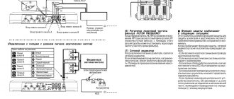
Amplifier circuit for tda7388
The figure shows a connection diagram for the tda7388 chip; capacitor C6 is necessary to regulate the on/off time and plays a significant role in optimizing clicks during transient processes. The minimum capacitance value for such a capacitor is 10 µF.
The input signal is supplied through capacitors with a capacity of 0.1 μF to pins 11,12,15,14 relative to the S-GND pin; with such a capacitance, the lower frequency of the medium will be 16 Hz.
To control the ST-BY or MUTE operating modes, you can use any low-power transistors, or the CMOS output of a microcontroller. RC chains are installed on these pins, which are necessary for smoothing control signals, otherwise control clicks may be heard when controlling the microcircuit. To control pin 22, about 10 μA is needed, so a 70 kOhm resistor is needed.
If there is any noise at the output of the amplifier, then it is necessary to install a first-order low-pass filter at the input, an RC circuit of 1 kOhm + 220 pF.
Amplifier circuit for tda7388
Amplifier madfeedback-1 (mf-1) on tda7293, tda7294 with hybrid OOS
The figure shows the connection diagram of the tda7388 chip, capacitor C6 is necessary to regulate the turn-off/off time and plays a significant role in optimizing clicks during transient processes. The minimum capacitance value for such a capacitor is 10 µF.
The input signal is supplied through capacitors with a capacity of 0.1 μF to pins 11,12,15,14 relative to the S-GND pin; with such a capacitance, the lower frequency of the medium will be 16 Hz.
To control the ST-BY or MUTE operating modes, you can use any low-power transistors, or the CMOS output of a microcontroller. RC chains are installed on these pins, which are necessary for smoothing control signals, otherwise control clicks may be heard when controlling the microcircuit. To control pin 22, about 10 μA is needed, so a 70 kOhm resistor is needed.
If there is any noise at the output of the amplifier, then it is necessary to install a first-order low-pass filter at the input, an RC circuit of 1 kOhm + 220 pF.