Power amplifier on Lm3886 chip (2*68 W) with tone control
We are studying the module - a power amplifier on the LM3886 chip. In the picture in the lower right corner there is a photograph of some other already assembled amplifier. The LM3886 chip is a class AB monophonic power amplifier (UPA) with very good characteristics. Popular with radio amateurs. With a small number of parts, you can assemble a ULF with the characteristics of industrial devices yourself for $200-300.
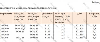
Let's look at the characteristics of this board:
1. Supply voltage: double alternating 20V-28V, it is recommended to use a transformer with two windings 26V and a power of 150 Watts 2. Output power - up to: 68W * 2 3. Load resistance: 4-8 Ohm 4. Dimensions: 15 * 9.3 * 5 cm
It came in a package with several layers of packaging: The board is additionally packed in film:
They included a package with accessories - two screws for attaching the microcircuits to the radiator, nuts and washers for attaching the potentiometers.
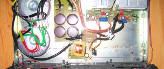
One op amp in the tone block seems to have been inserted into the socket using a press: Dimensions of the board: You can see from the photograph that the circuit is divided into 4 parts: preamplifier-tone block, ULF, speaker protection and power supply. The board is double-sided. Reverse side of the board:
The flux was washed to 4 degrees. If you install this amplifier somewhere for constant use, it is better to wash the board with flux remover. Let's see what parts are used in this amplifier: Power supply filter capacitors, speaker protection relays and terminals for its connection:
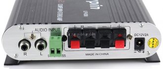
I liked the terminals - they fix everything firmly, the thick wire fits in without any problems. For some reason, the terminals for connecting speakers were located on the front panel of the board. Or should I connect the speaker wires from the back to these terminals?
RCA - input connectors. Not only is the bottom connector wired crookedly, but the tulip does not fit into it at all. Expanded.
Behind the input jacks there are three holes for installing a block if the location of the input jacks for some reason does not work (for example, we want to place it on the rear wall of the case).
Capacitors between the tone block and ULF chips: Hi-emd quality from the well-known company JIE DUE DENC:
ULF chips LM3886TF. The housing is plastic (TF), can be attached to a radiator without an insulating backing. Real or fake chips - unclear:
The tone block-preamplifier uses NE5532 operational amplifiers (op-amps). The board indicates the possibility of replacing it with a higher class op amp - AD827, OPA2604.
Let's weigh the fee:
Amplifier circuit
I drew the diagram based on the board. There may be some errors. If anyone notices, write. I'll correct it. I find the placement of the volume control a little odd. As you can see from the diagram, the LM3886TF chip is turned on in normal mode.
To connect we will use a 250 Watt transformer: According to the passport, there are two windings of 25 V, 4A:
We screw the radiator to the microcircuits, load resistors 8 Ohm 100 W, connect the power:
We measure the supply voltage at the output of the transformer (the signal is not supplied to the ULF): According to the passport, 25 V alternating voltage, in fact 27.6 V. Maybe this is for the best :-). The amplifier description can use up to 28 VAC power.
After the rectifier and filter capacitors: 37.3 V. The microcircuit will operate almost at its limit. This is bad. It is better to use a 20-22 V transformer. On the tone block after the stabilizers (there are contact pads for measurements on the measurement board) - 12 V.
Let's check the constant voltage at the output of the ULF (This voltage damages the speakers, this ULF has protection against constant voltage, but we'll check it anyway):
Everything is normal with a constant output. We connect a signal generator to the ULF input, a volume control (RG) and an oscilloscope to the output. Load 8 ohms. We supply a standard sinusoidal signal at 1 kHz and increasing its value, we introduce the amplifier into clipping (clipping - cutting off, clipping, cutting - a form of sound distortion, expressed in limiting the amplitude of the signal when the output voltage of the amplifier exceeds the supply voltage limit):
On the signal generator:
It turns out that the amplifier can develop power P=U*U/R=58/2*58/2/8=105 Watts. Prms=105/2=52.5 Watts If clipping is removed, then we get:
Maximum power 87 watts. Prms=87/2=43.5 Watt Let's change the signal shape (leave the input signal level unchanged) rectangular. True, at first the signal was not rectangular. I turned the tone controls and achieved a more or less rectangular appearance:
Let's change the signal shape again to triangular:
Now let's connect the amplifier to the sound card and run tests in the RMAA program. Let's look at the frequency response of the ULF (tone controls in the middle position, a rectangular signal at the input -> so that there is a rectangle at the output):
Other dimensions
Tone controls max. position:
Tone controls in min. position:
To prevent the tone controls from affecting the measurements, I unsoldered the input terminals of the capacitors (large red Hi-emd quality from the well-known company JIE DUE DENC), applied a signal to the input and carried out measurements. Frequency response:
Other dimensions of Lm3886
I listened to the amplifier. I connected the acoustics (Mission M51). Source ESS0204. There is no background. For min. When the volume control is set to ULF, music can be heard very quietly in the speakers. There is no crackling noise when turning the controls (volume, timbre) at ULF. There is no channel misalignment. It plays cleanly, and the amp somehow emphasizes the mid-high frequencies. Apparently this is a feature of the Lm3886 chip. I like the Hood amplifier 1969 () better in terms of sound.
The product was provided for writing a review by the store. The review was published in accordance with clause 18 of the Site Rules.
↑ Background
Another small note about the network background.
I have already said that on the amplifier board itself, in the power supply, electrolytic capacitors of a fairly large capacity are installed - 4700 mF in each arm. However, when connecting the power supply pins of the amplifier directly to the corresponding terminals of the diode bridge, the hum in the speakers was audible, although not significant. After installing additional electrolytes of 10,000 mF in each arm to the diode bridge terminals, the background practically disappeared. In addition, it was concluded that the microcircuit “forgives” errors in installing the power supply, since my power supply was “screwed up”... And large capacitors were hanging on thin wires.
However, I do not call for a careless attitude in the design of this device, and, nevertheless, I advise you to pay due attention to the organization of the power supply.
↑ My circuit on TDA7293
Switching on is also an inversion, the OS is also T-shaped. And again, the board is as compact and simple as always.
The grinder can’t be moved too far - again two independent channels!
Maybe someone recognized the radiators in the photo? It was the Oda-102
. Small one, from a block stereo complex. Once upon a time I got it for free without speakers, I even used the transic from the tape recorder in one of the DACs, but the tuner, pre and power were lying around idle. The power trance was taken from there. I don’t need kilowatts of power, I’m no longer at that age to measure the length and thickness with my neighbors, so if I have 20 watts, that will be enough for me, and there will be some left for my neighbor.
For the tests, two identical power supplies were made, more precisely 2 boards of rectifiers and filter capacitors, as well as a universal connector for connecting two different power transceivers, one from Oda, the second from an active Behringer speaker.
↑ Results and conclusions
The amplifier turned out to be in an original, nice and relatively small case.
Plexiglas painted on the inside looks good. By sound:
The sound cannot be called “tube” in the full sense of the word, but it is quite pleasant. I have no way to compare the sound with amplifiers on this chip made using other circuits, or with other brick-and-mortar amplifiers, so I cannot say whether it sounds better or worse. The main criterion for me is that even listening for 6 hours does not tire me at all. This is a good indicator for me. Well, once again I would like to remind you that a lot depends on capacitor C1. He's the boss here!
Frequency response and harmonics of the amplifier in pictures:
The presented characteristics were taken with an 8 Ohm load (20 W resistor) and an output voltage of 11 V (15 W).