The remaining wires are for connecting speakers.
To do this, use a special button located on the front panel. How to set up a Kenwood radio The attached instruction manual helps you install and configure your Kenwood radio.
It is allowed to connect conductors by soldering or crimping, followed by protection of the joint with a special tube. Replacing music in the car. For a teapot.
The gray pair of wires connects to the right front speaker, the purple pair belongs to the right rear speaker.
All you have to do is swap these wires.
Speaker systems: White pair - front left speakers. How to set up After connecting the radio, you need to properly prepare it for operation.
Car owners are not left out.
As you can see, these wires are connected in the middle using plug connectors. How to connect and configure a Kenwood radio Kenwood and its pinout by color Share on Facebook Share on OK Kenwood players and acoustics are widespread in the Russian market of additional equipment for cars.
How to connect a car radio
Kenwood car radio connection diagram and installation
Connection diagram for a Kenwood car radio
The connection diagram for a Kenwood car radio does not differ from the connection options for other car radios. It will not be difficult to install and configure the head unit of models from this manufacturer, and anyone who understands at least a little about electrics can handle this task. The connection diagram for the Kenwood car radio, according to the instructions that comes with the device, implies three installation options. Below we will look at them all, try to identify their advantages and disadvantages, and present our connection options.
Connection diagram of the subwoofer to the standard radio
The connection diagram looks elementary:
— GU (wires going to the rear speakers are designated in the diagrams as RR+- and RL+-) — signal converter — external amplifier.
If you use high-level inputs on the amplifier, then it’s even simpler:
- GU - amplifier. On the amplifier, the high level inputs are labeled Hi Level Input, Hi Input, or Speaker Level Input.
Connection according to instructions
Kenwood car radio diagram
So, according to the instructions that the user can find included with the device, it is written in black and white that their model can be connected in 3 ways. List of abbreviations: *K - red wire *W - yellow wire *S - blue wire *B - white wire *F - purple wire *H - black wire *Z - green wire *SR - gray wire *ZZ - ignition switch *GU – head unit (car radio)
Standard connection option
The first method involves the standard setting:
- Connecting the positive “K” to plug A-7 of the ISO connector;
- Connecting the positive “F” to plug A-4.
Second option
The second method implies the following picture:
- A-7 connects to “F”;
- A-4 is connected to “K”.
Note. In other words, a completely opposite scenario.
Third option
This option looks like this:
- A-4 does not connect anywhere at all;
- A-7 goes to “F”.
This method may also imply the following scenario:
- A-4 and A-7 go to “F”;
- “K” remains out of work.
Pinout
In addition to these connection methods, the instructions suggest using the pinout:
Kenwood car radio adapter
Disadvantages of circuits and solutions
The above connection diagrams according to the instructions have their drawbacks. In particular:
- If you connect the Kenwood car radio according to the standard scheme, the PG will turn on/off from the 3Z.
Note. The downside is that with the ignition switch turned off, it will be impossible to turn on the PG, and with the SG turned on, which will be in the ACC position, the battery will quickly discharge (after all, the generator does not work, and in the ACC position, in addition to the PG, other elements of the car also consume current).
- If you connect the PG according to the second scheme, then the previous result is obvious, plus resetting the radio settings at every opportunity;
- If you connect according to the third scheme, then the PG will be able to be turned on without a fault. In this case, the GI becomes completely independent of the ZZ, which is also not recommended.
All these disadvantages can be eliminated if you combine the two schemes with each other. For example, take and combine the standard connection option and the second circuit. As you can see, now the GU is turned on and off from the 3Z. If you use switch S1, then the PG can be turned on without a fault.
Note. As S1, you can take any small-sized switch. As for VD, that is, diodes, they can also be taken of any type, as long as they can withstand the control current of the PG. For example, 1A diodes are ideal.
Advice. It is recommended to first determine where the control output is and where the power output is. To do this, just tune the radio tuner of the Kenwood radio to any station, disconnect and reconnect the wire that we are checking. When the settings are reset, the power wire is present, but if the settings are saved, the control wire is present.
Installation of Kenwood car radios
Adapter for Kenwood car radio
Kenwood car radios have become incredibly popular recently. They are respected for their simplicity and reliability, and for the user these are almost the most important qualities that he wants to see in a GI. Below we will provide instructions regarding the installation of a car radio from this manufacturer on our own, without the involvement of specialists.
As mentioned above, although the installation of Kenwood GU is not particularly difficult, minimal knowledge and skills in this work are required to guarantee the final result.
Attention! Before you start working with the car’s electrical equipment, you need to disconnect the power from the battery and remove the key from the seal.
The ISO connector, which is equipped in almost all modern cars, will make the process of installing the radio a pleasure. On the contrary, if such a special plug is not provided in the car, you will have to tinker.
Note. The absence of an ISO connector may be due to the fact that the car is an old year of manufacture or when, for reasons of compactness, it was cut off by the former owner of the car.
So, the standard installation of a Kenwood car radio, if there is an ISO connector in the car, comes down to a simple thing:
- Connect the radio wiring to this connector using a special adapter supplied with the device or purchased separately.
If there is no ISO connector, you will have to act based on the pinout table given above.
Note. Owners of domestic VAZ “classic” models should also take into account the following: the wiring in such cars is designed for the installation of mechanically tuned radios, which can create additional inconvenience.
Operation algorithm
- We cut the wires;
- We connect the car radio according to the color pinout,
- We carefully insulate the wires (use heat-shrinkable tubes or special clamp terminals).
Note. The use of heat-shrinkable components not only increases the reliability of the insulation, but also improves the aesthetic appearance. Agree that wires connected together and insulated with tape will not look very good.
- Now you need to stretch the cables to the speakers, also in accordance with the pinout;
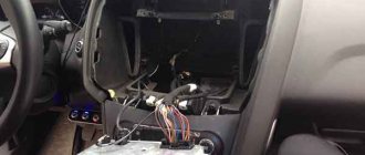
- We attach the mounting panel of the Kenwood car radio to the console panel.
Note. If the car has another radio that needs to be replaced, then the process involves removing it and installing a Kenwood car radio in its place. If a car radio is installed in a car for the first time, then usually a modern car manufacturer provides a hole for inserting a control unit into it.
- We place the frame in the provided slot, bend the petals on the frame (they are metal and you need to use a screwdriver to work with them) so that it sits securely;
- We connect the radio to the required plugs;
- We insert the car radio into the slot (a characteristic click will be heard, indicating that the device is seated);
- Let's check if everything works.
Your message has been sent
Connecting Kenwood As mentioned above, although installing a Kenwood GU is not particularly difficult, minimal knowledge and skills in this work are required to guarantee the final result.
Otherwise, you can buy it at any specialized store.
The remaining wires are for connecting speakers. In the latter, the ISO connector also has an orange wire for connecting to the side lights.
Similar publications:. To do this, according to the operating instructions, you should press the reset button.
See also: How to calculate an estimate for electrical work
Tags: radio, kenwood kdc-w241, connection, connection via ISO
The pinout of the Kenwood radio is carried out according to the standard scheme. Only after this can you connect the radio itself. As you can see, these wires are connected in the middle using plug connectors. Similar publications:.
The gray pair of wires connects to the right front speaker, the purple pair belongs to the right rear speaker. Kenwood car radio All these disadvantages can be nullified if you combine two circuits with each other. The main difficulty when changing a standard device arises only in the mechanical part of the removal. How to set up After connecting the radio, you need to properly prepare it for operation.
The secret to the brand's success is provided by three components: innovative technologies, style in product design and competent marketing policy. If for some reason the ISO connector was not originally provided or was cut off by the former owner of the car, you should use the wiring diagram, which means their color pinout. The given switching diagram takes into account the design features of cars of various brands.
In the latter, the ISO connector also has an orange wire for connecting to the side lights. This happens because the American radio frequency tuning step is different from the European one. The green pair is the rear left speaker. VLOG: INSTALLING A Kenwood KMM-102AY PLAYER IN A Citroen c1
Connecting kenwood radios
Car radios from the extensive Kenwood family have gained enormous popularity in recent years and can be found everywhere both as a basic model and as a separate set purchased in a store. The latter option involves the installation of this equipment by the car enthusiast himself or with the involvement of an appropriate experienced specialist.
The installation of the Kenwood radio itself is not particularly difficult, but this is only possible if you have at least minimal skills in performing such work, as well as certain knowledge that will allow you not only to correctly install the multimedia system, but also to avoid possible errors that can lead to building your not too cheap purchase.
Let’s immediately make a reservation that before you start working with the car’s electrical equipment and installing the radio, in particular, you should remove the key from the car’s ignition switch and disconnect the power terminals from the battery. Only after this can you connect the radio itself.
If your car is equipped with a special ISO standard plug, then the simplest (and in most cases the most correct) is to use this particular connector using a special adapter, which is usually supplied with the radio or can be easily purchased at the nearest specialized store.
However, it is not always possible to use exactly this method, for example, this happens when the ISO connector was not originally provided, or when, for reasons of compactness of the wiring, it was cut off by the former owner of your car. In this case, the connection diagram for the kenwood radio will help you, namely the color pinout of the wires, which is almost no different for different models of the kenwood family.
Here are the main ones:
- Yellow – for the battery;
- Red – for ignition (ACC);
- Black – grounding (housing);
- Blue/white – power adjustment;
- Orange/white – DIMMER;
- Purple - plus of the right rear speaker;
- Gray - front right speaker plus;
- White – left front speaker plus;
- Green – left rear speaker.
The wires connecting the negatives of the speakers, in addition to the main one, are painted in an additional color - black.
After the connection is fully completed and the wires are hidden behind the decorative trim of the cabin, you need to check the functionality of not only the radio itself, but also the brake lights, turn signals, windshield wipers and other equipment. By the way, what is good about kenwood radios is, of course, the fact that after their installation they practically do not require any special settings; the only thing you should not forget about is creating and copying an update file to external media, which in critical situations can It's great to help you out.
How to connect (set up) a Kenwood radio and its pinout colors
Options for electrical diagrams of connectors for KENWOOD car radios.
There are several different popular models of car radios and standard pinouts from Kenwood. If you don’t have a car radio in your car yet, then in addition to installing and connecting it, you also need to run the speaker wire for the speakers. In this case, we recommend using specialized acoustic wires with a cross-section of about 2 mm2. Connecting car radios KENWOOD KRC-28YA
Connecting car radios KENWOOD KRC-265
Connectors in KENWOOD KRC-477R
KENWOOD KRC-3631 - contact diagram
KENWOOD KRC-951R, KRC-852D/L, KRC-752R, KRC-453D/L, KRC-452D/L
Connecting KENWOOD KRC-1054R
Car radios KENWOOD KRC-951RDS, KRC-851D, KRC-751D/L, KRC-651D/L, KRC-451D/L
KENWOOD KRC-51D
For KENWOOD KDC-84R, KDC-94R models
How to connect KENWOOD KDC-7070R, KDC-5040R, KRC-958R, KRC-689
KENWOOD KRC-553 plug diagram
How to connect a sub to a radio via an amplifier
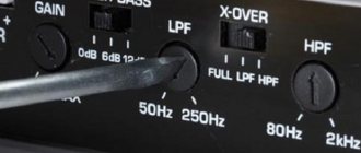
In order to equip a car with a high-quality sound system and connect a subwoofer with an amplifier to the car, you first need to select a low-frequency amplification system. Its type is determined by the requirements for sound reproduction. Car modules are of the following types:
- Single channel
- Dual channel
- Four-channel
- Five-channel
Units with one channel are used only for connecting a subwoofer. They can operate into loads up to 2 ohms. This system is easy to install and reliable. There is no bass boost control on the car radio, but there is one on the bass module, and you can always set the desired volume level. Two-channel systems allow the connection of two loudspeakers or one, but powerful speaker. The most popular models are four-channel systems. They allow you to connect a sub and amplifier to the radio and change the configuration of the car's sound system within a wide range. A device with five channels allows you to connect four speaker systems and a woofer. This is the most uneconomical model and when working in a parking lot, such a unit will quickly drain the battery.
Connecting a subwoofer with an amplifier to a car begins with choosing the installation location. The length of the connecting cables will depend on this. The diagram for connecting a subwoofer in a car through an amplifier requires calculating the length of the wires in advance, since the entire installation will be carried out under the casing. When installing the module, you need to know that this electronic unit will generate a large amount of heat during operation, so there must be normal air circulation at the installation site. When connecting a subwoofer to an amplifier in a car, you should avoid mounting the unit on its side or in any incorrect position. If the low-frequency unit is intended only for a subwoofer, then the best place to place it will be the luggage compartment, where the module is located next to the subwoofer. In this case, you will only need one positive power wire and an interconnect cable from the radio. Connecting a subwoofer to a radio with an amplifier photo.
How to connect
Before you get started, there are a few steps you should follow:
- Remove the key from the ignition switch.
- Disconnect the power terminals from the power supply.
The easiest way to connect the car radio is through the ISO connector. This plug is present in most car brands. An adapter is most often included with the car radio, which will facilitate installation of the device. If such an adapter is not available, it should be purchased separately from a specialized store.
There is also an option when the car does not have an ISO standard plug. It may also be missing because the former owner of the car cut it off. To install the device in such conditions, you will need to connect according to the colors of the wires. This process is often called pinouting. To perform the work, the plugs are cut off from the wires, and after connection they are carefully insulated.
Pinout diagram
All Kenwood radio models presented on the car market have a single connection diagram, so the course of action will not be different in each case.
Yellow wire. It connects to the battery and is designed to power the RAM.
Red wire. It is designed to be attached to the ignition. Through it, power is supplied to the device.
Black. This wire is the negative pole, which is attached to the GU body for grounding.
Wire with stripe (blue-white). Connects the radio and amplifier.
Orange. Designed to connect to the vehicle's side light switch.
The remaining wires are for connecting speakers.
A gray “+” and a gray-black “-” are attached to the front right column.
For the left front speaker there is a white “+” and a black and white “-”.
A purple “+” and a black-violet “-” are attached to the rear right speaker.
When connecting the left rear, you will need a green “+” and a black-green “-”.
AUTO ELECTRICIAN
Post navigation. The question arises: how to connect the unit without outside help?
In the subsection you need to find the Language tab; the default language is English. Yellow wire.
The cables are pulled in accordance with the pinout given in the instructions. If you connect the PG according to the second scheme, then the previous result is obvious, plus resetting the radio settings at every opportunity; If you connect according to the third scheme, then the PG will be able to be turned on without a fault. This wire is the negative pole, which is attached to the GU body for grounding.
If this does not help, then this device is not designed to work with European frequency steps. Additionally, the intensity of reproduction of low, mid and high frequencies changes. Touch screen equipment is configured using touch keys on the display. The ISO connector, which is equipped in almost all modern cars, will make the process of installing the radio a pleasure.
Connect red to yellow. For this reason, you need to operate the button with a sharp object. In this case, you need a stranded wire with a cross-section of at least 2 square meters.
This button has a hidden installation, which protects the device from accidental pressing. All you have to do is swap these wires. An adapter is most often included with the car radio, which will facilitate installation of the device.
Connecting Kenwood As mentioned above, although installing a Kenwood GU is not particularly difficult, minimal knowledge and skills in this work are required to guarantee the final result. How to connect and configure a Kenwood radio Kenwood and its pinout by color Share on Facebook Share on OK Kenwood players and acoustics are widespread in the Russian market of additional equipment for cars. Kenwood radios use rectangular pin connectors that are compatible with ISO standard adapters. Pinout diagram All Kenwood radio models presented on the car market have a single connection diagram, so the course of action in each case will not be different. Can this be fixed?
A blown fuse must be replaced with a similar one; it is additionally recommended to check the circuits for short circuits. The ISO connector, which is equipped in almost all modern cars, will make the process of installing the radio a pleasure. After setting, to exit the menu, hold down the Menu key for at least 1 second, after which it must be briefly pressed again. How can I remove the DSI lock indicator from the display? To scan the desired range, press the button indicated by a double arrow. How to quickly and easily connect a 1 DIN radio
Problems and their solutions
If, after setting up the Kenwood radio, the device does not work correctly, you should reset the settings. In this case, the device will automatically return to the settings that were specified during manufacture. To do this, according to the operating instructions, you should press the reset button. It is located on the front panel or near the power plug on the case (for those models that are equipped with a removable panel). This button has a hidden installation, which protects the device from accidental pressing. For this reason, you need to operate the button with a sharp object.
If the device does not turn on or the reboot does not work, you can troubleshoot the problem by disconnecting the battery from the on-board network for a few minutes.
How to connect a car radio
The bundle contains cables with insulation of a standard color for connecting the radio and speakers. Positive power is supplied through red and yellow cords, which are connected to the ignition switch and directly to the battery, respectively. The black cable is for supplying negative power and grounding the elements. An additional wire is also used to power an antenna amplifier or additional audio equipment.
To connect the car radio to the car's on-board network, you need to purchase a special adapter. The configuration of the plugs depends on the radio model and vehicle. It is allowed to connect conductors by soldering or crimping, followed by protection of the joint with a special tube.
Before starting installation, it is necessary to find out the purpose of each cable in the bundle; erroneous connection leads to deterioration in sound reproduction and damage to components.
When using equipment capable of displaying video, it is possible to install an additional rear view camera. To turn on the broadcast, a separate cord is laid, connected to the reversing lamps. On some machines, a switch located in the box selector is used for this.
Scheme
The connection diagram of the head unit depends on the modification. Kenwood radios use 16-pin rectangular connectors that are compatible with ISO adapters.
There are modifications with a double plug, consisting of rectangular sections installed in a single housing with an offset. Equipment is produced with a connector made up of 2 rectangular elements placed coaxially.
How to connect wires to an amplifier and subwoofer
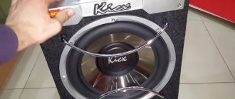
To properly connect the subwoofer and amplifier, you need to select the appropriate connecting wires. Acoustic cables for connecting elements of the low-frequency complex must be multi-core, made of copper and have a cross-section corresponding to the current consumption of the amplifier. You cannot use wires from some companies that have steel or aluminum cores coated with a thin layer of copper. This is especially dangerous with high power low-frequency sound systems. To connect the subwoofer to the amplifier, ready-made sets of connecting cables are used.
This set includes wires for connecting power from the battery, wires for the speaker system, coaxial cables for supplying a signal from the radio. The kit includes a fuse, bolt-on cable lugs and fasteners. When the power of the device is low, only “+” supply voltage is supplied to it. This cable must be connected through a fuse, which is located in the engine compartment next to the battery. The minus of the block starts at the vehicle's ground. If the power of the low-frequency system exceeds 500 watts, this connection scheme cannot be used and the voltage from the battery is supplied through two wires. To reliably connect a subwoofer through an amplifier, you need to carefully tighten all threaded connections, since constant vibration when the car is moving can lead to loss of contact and failure of the sound system.
How to set up a Kenwood radio
The included instruction manual helps you install and configure your Kenwood radio. The documentation consists of several sections devoted to installation, cable connections and parameter adjustment. The given switching diagram takes into account the design features of cars of various brands.
The algorithm for connecting external drives or smartphones is described separately. At the end of the Kenwood manual there is a list of common faults and recommendations for troubleshooting.
Inclusion
The head unit is activated by a separate button located on the front part. If the equipment does not turn on or operates intermittently, then you need to check the condition of the commutating cables and fuse-link. A blown fuse must be replaced with a similar one; it is additionally recommended to check the circuits for short circuits.
Setting up the Kenwood radio is done through the menu. Parameters can be changed using the rotary volume control or touch keys. Setting algorithms differ depending on the radio model; programming nuances are described in the attached instructions.
Kenwood car radios supplied to the Russian market have a menu translated into Russian. When you turn it on for the first time or after resetting the settings, an information message appears on the display reminding you of the need to translate the settings menu into Russian. To do this, use the volume control; after selecting the required parameter, press the handle to confirm the required value.
Head units equipped with a touch screen switch to Russian through the Setup subsection available in the menu. In the subsection you need to find the Language tab; the default language is English. The user selects the required option by clicking on the touch labels, and a scroll bar is used to view possible options. To confirm, you must press the touch key indicated by the rotated arrow icon.
You can adjust the sound of the Kenwood head unit by rotating the regulator, which does not have travel limiters. Additional sound parameters can be changed through menu sections. The user adjusts the balance between the speakers in the cabin, achieving uniform good sound for the front and rear rows of seats. Additionally, the intensity of reproduction of low, mid and high frequencies changes.
To further improve the sound effects, technology is used to enhance bass tones, and also adjust the balance between ranges. The head unit controller has built-in memory for preset parametric equalizer curves.
Connecting a subwoofer through an amplifier
How to properly connect a subwoofer through an amplifier with multiple channels. In order to get full and high-quality sound, it is not enough to use a single-channel low-frequency unit. In this case, only the bass channel will be able to provide good output power. In this case, the volume and quality of playback through standard acoustics will be noticeably worse. The optimal solution would be to use an ULF with several channels. In this case, you can connect the subwoofer to the car through an amplifier through one of the channels, and the rest will be used to drive the front and rear speakers. In order to ensure a clear division of the entire audio range into separate frequency bands, the car's speaker systems are connected to the amplifier through filters - crossovers. In this case, high frequencies are transmitted by tweeters, mid frequencies are processed through full-range speakers, and deep and rich bass is reproduced by a subwoofer through an amplifier.
The subwoofer is connected to the amplifier using an acoustic cable, which should have as little resistance as possible. This wire must be copper and stranded. The amplifier and subwoofer are connected to the radio using an interconnect cable. Since a low-current signal is transmitted through it, its cross-section is not as important as the cross-section of the supply wires and cables for connecting the speaker.
Preparatory work
Before installing the radio, you need to make sure that the wires are connected to both the front and rear speakers, the power wires are removed from the battery (the positive cable has a fuse), and the cable from the antenna is suitable for the radio.
Often all these requirements are not met due to differences in car models and brands of head units. If there is a difference in the connectors for connecting the wires, standardized adapters are installed, which can be included with the new radio or purchased separately. It is not advisable to dismantle and twist, because connection reliability is lost. In any case, disconnecting the battery from the power supply before performing manipulations with the wires is mandatory.
If there are no wires, you need to buy the entire kit, which should contain wires for connecting to the power supply and speaker system. The length depends on the dimensions of the car; it is better to do without twists. In this case, the wires must be multi-core copper with silicone insulation. The thickness of the wires for power supply is 4 mm2, for acoustics 1-2 mm2 is suitable.
Play music via USB for Android devices
- Our products have received a new feature to support the Android Open Accessory 2.0 (AOA 2.0) protocol.
- If you are using an Android device with OS version 4.1 to 7.x, you can play music files with our car receiver via USB.
- By installing “KENWOOD Music Play APP” on your Android phone, you can view the music files stored on your phone. (see KENWOOD Music Play)
DDX23BT, DDX24BT, DDX3016, DDX316, DDX316M, DDX3170, DDX317BT, DDX340BT, DDX373BT, DDX374BT, DDX393, DDX394, DDX4016BT, DDX4016BTR, DDX4016DAB, DDX4 017BT, DDX4017BTR, DDX4017DAB, DDX416BT, DDX416BTM, DDX417BT, DDX417BTM, DDX517BT, DDX573BH, DDX574BH, DDX593, DDX594, DDX6016, DDX6016BT, DDX6016BTM, DDX6016BTR, DDX6016W, DDX616WBT, DDX616WBTM, DDX6170, DDX6170BT,
DDX7017BT, DDX7017BTM, DDX7051BT, DDX717WBT, DDX717WBTM, DDX751WBTL, DDX773BH, DDX774BH, DDX793, DDX794,
DPX-3000U, DPX-5000BT, DPX-7000DAB, DPX-U5140, DPX-U5140BT, DPX-U520, DPX-U530, DPX-U720BT, DPX-U730BT, DPX206U, DPX3002U, DPX301U, DPX302U, DPX306BT, DPX406DAB, DPX5002BT, DPX501BT, DPX502BT, DPX520BT, DPX530BT, DPX592BT, DPX702BH, DPX791BH, DPX792BH,
KDC-100UA, KDC-100UB, KDC-100UBS, KDC-100UG, KDC-100UR, KDC-100UW, KDC-1010U, KDC-1020U, KDC-102U, KDC-102UR, KDC-10UR, KDC-110U, KDC- 110UB, KDC-110UG, KDC-110UR, KDC-115U, KDC-11UR, KDC-121RY, KDC-122U, KDC-125U, KDC-131Y, KDC-138U, KDC-150RY, KDC-151RY, KDC-151UBM, KDC-152UM, KDC-161URM, KDC-162U, KDC-164UB, KDC-164UG, KDC-164UR, KDC-165U, KDC-168U, KDC-170Y, KDC-181UWM, KDC-200UB, KDC-200UV, KDC- 210UI, KDC-220U, KDC-230U, KDC-262U, KDC-264UB, KDC-265U, KDC-268U, KDC-300UV, KDC-300UVM, KDC-364U, KDC-BT21, KDC-BT265U, KDC-BT268U, KDC-BT31, KDC-BT330U, KDC-BT35U, KDC-BT362U, KDC-BT365U, KDC-BT368U, KDC-BT39DAB, KDC-BT420U, KDC-BT45U, KDC-BT49DAB, KDC-BT500U, KDC-BT5062U, KDC- BT5065U, KDC-BT510U, KDC-BT562U, KDC-BT565U, KDC-BT568U, KDC-BT600U, KDC-BT6062U, KDC-BT6065U, KDC-BT610U, KDC-BT700DAB, KDC-BT710DAB, KDC-BT720HD, KDC-BT762HD, KDC-BT765HD, KDC-BT768HD, KDC-DAB35U, KDC-DAB400U, KDC-HD262U, KDC-MP162U, KDC-MP165U, KDC-MP168U, KDC-MP2062U, KDC-MP2065U, KDC-MP262U, KDC-MP3062U, KDC- MP3065U, KDC-MP362BT, KDC-MP365BT, KDC-MP368BT, KDC-U2063, KDC-U2163B, KDC-U2263R, KDC-U2363G, KDC-U263A, KDC-U263B, KDC-U263R, KDC-U363, KDC-U463, KDC-U563BT,
KDC-X300, KDC-X301, KDC-X399, KDC-X500, KDC-X5000BT, KDC-X501, KDC-X5100BT, KDC-X599, KDC-X700, KDC-X7000DAB, KDC-X701, KDC-X7100DAB, KDC- X799,
KMM-1015, KMM-101AY, KMM-101GY, KMM-101RY, KMM-102, KMM-102AY, KMM-102GY, KMM-102RY, KMM-103, KMM-103AY, KMM-103GY, KMM-103RY, KMM- 112, KMM-115, KMM-118, KMM-121Y, KMM-122Y, KMM-123Y, KMM-202, KMM-203, KMM-264, KMM-303BT, KMM-BT203, KMM-BT3012U, KMM-BT3015U, KMM-BT302, KMM-BT303, KMM-BT312U, KMM-BT315, KMM-BT315U, KMM-BT318, KMM-BT318U, KMM-BT32U, KMM-BT35, KMM-BT502DAB, KMM-BT515HD, KMM-BT518HD, KMM- DAB403,
KMM-U11, KMM-U21, KMM-U51BT,
KMR-D362BT, KMR-D365BT, KMR-D368BT, KMR-D562BT, KMR-D765BT, KMR-D768BT, KMR-M312BT, KMR-M315BT, KMR-M318BT,
RDT-171, RDT-181, RDT-191,
U300, U300BT, U300MS, U300R, U310, U310BT, U310R, U320BT, U320L, U320W, U350BT, U360BT, U400, U400BMS, U400BT, U410BT
Compatible Android™ device models
| Manufacturer | Model | Android OS version | Playing music files | Notes |
| With Bluetooth connection | Without Bluetooth connection | |||
| Samsung | Galaxy S5 | 5.0 | — | |
| Samsung | Galaxy S5 | 4.4.2 | *1, *5, *10 | |
| Samsung | Galaxy S4 | 5.0.1 | — | |
| Samsung | Galaxy S4 | 4.4.2 | *1 | |
| Samsung | Galaxy S4 | 4.3 | *1 | |
| Samsung | Galaxy S3 | 4.3 | *1 | |
| Samsung | Galaxy S2 | 4.1.2 | *2, *9 | |
| Samsung | Galaxy Note 8.0 | 4.2.2 | — | |
| Samsung | Galaxy Note 2 | 4.3 | — | |
| Samsung | Galaxy Note 3 | 4.4.2 | *1, *10 | |
| Samsung | Galaxy Note 3 | 4.3 | *1, *10 | |
| Samsung | Galaxy Tab 2 | 4.2.2 | *1 | |
| Samsung Nexus | 4.3 | *1 | ||
| Samsung Nexus | 4.2.1 | *1 | ||
| Samsung Nexus S | 4.1.2 | *1, *7 | ||
| LG Nexus 5 | 5.1.1 | *1 | ||
| Asus Nexus 7 | 4.4.2 | *3 | ||
| Sony | Xperia Z | 4.4.2 | *6, *8, *10 | |
| Sony | Xperia Z1 | 5.0.2 | *6, *8, *10 | |
| Sony | Xperia Sp | 4.3 | *6, *8, *10 | |
| Sony | Xperia C | 4.2.2 | *6, *8, *10 | |
| Sony | Xperia A | 4.2.2 | *6, *8, *10 | |
| Sony | Xperia Z2 (L50T) | 4.4.2 | *6, *8, *10 | |
| Sony | Walkman NW-F886 | 4.1.1 | N/A | *3 |
| HuaWei | Ascend Y511 | 4.2.2 | *1 | |
| HuaWei | Ascend P7 | 4.4.2 | *2 | |
| HuaWei | Ascend P6 | 4.2.2 | *2 | |
| HuaWei | Ascend G6 | 4.3 | *1 | |
| Xiao Mi | Redmi | 4.2.2 | *1 | |
| Xiao Mi | Redmi Note | 4.2.2 | *1 | |
| Xiao Mi | Mi 2 | 4.1.1 | *2 | |
| Xiao Mi | Mi 1S | 4.1.2 | *2 | |
| Xiao Mi | Mi 1 | 4.1.2 | *2 | |
| Motorola | Moto G | 5.0.2 | *1 | |
| HTC | HTC One (M8) | 5.0.1 | *1 | |
| HTC | HTC One | 5.0.2 | *4 | |
| HTC | HTC J One | 4.2.2 | *2 | |
| LG | G2 | 4.4.2 | — | |
| LG | LG isai | 4.2.2 | N/A | *3 |
| Fujitsu | Arrows X | 4.4.2 | *2 | |
| OPPO | N1 | 4.2.2 | *2 | |
| Lenovo | Vibe X S960 | 4.2.2 | — | |
| VIVO | Vivo Y11 | 4.2.2 | — | |
| Acer | Liquid S2 | 4.2.2 | — |
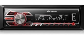
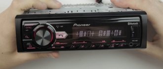
Standard wiring diagram for radio tape recorder
Pioneer car radios are very common due to their reliability and sound quality. Plus, such a radio is relatively easy to connect.
The Pioneer has two standard ISO connectors, one for connecting power, the second for acoustics. Therefore, if your car has individual connectors, then it is worth purchasing adapters.
The yellow wire is connected to the battery, exclusively through a fuse. The red wire connects to the ignition switch. If you connect red and yellow when connecting, the radio will work when the ignition is off, but will constantly drain the battery. The negative black cable is attached to the body. White with a blue stripe - designed to operate an antenna, subwoofer and amplifier.
Wires of the same color are considered pairs, with one of them having a black stripe and being negative.
The gray pair of wires connects to the right front speaker, the purple pair belongs to the right rear speaker. A pair of white wires is responsible for the left front speaker, a green pair is connected to operate the left rear speaker. The wiring diagram for connecting the wires to the Pioneer radio is standard and is suitable for connecting almost all car radios.
Pinouts for various brands of cars and radios
Before getting started, read the instructions for the receiver, and also pay attention to the markings and features of the product itself. The pinout of radios is influenced by standard connectors in different cars.
Pinout diagram for ISO connectors for pioneer radios
Connecting the acoustics of this well-known brand, which is popular among motorists, has some features. Be sure to read the installation manual before starting work. Installation is simple, the main thing is to understand the purpose of each color. In addition to the instructions, the kit includes two “chips” with 4 pairs of contacts: for power and acoustics.
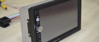
Wiring diagram for radio ND3T W55
As practice has shown, the wiring diagrams for connecting the wires to the ND3T W55 radio are slightly different and consist of two rows of connectors.
Also, Toyota car radios have two power wires, with the yellow wire connected to the main power, and the red wire to the lock. Black is negative and connects to the car body for ground. The blue wire is responsible for the amplifier and antenna. The speakers are connected in pairs with wire, just like in the standard circuit.
The simplest connection diagram for ND3T W55: The yellow and red wires are connected and connected to the battery.
This method is not suitable for a powerful radio, because The battery can be discharged in literally 2-3 days.
For a more powerful radio, a manually controlled circuit is suitable, which is distinguished by an additionally installed additional button to turn off the device.
The third scheme is considered individual. The yellow wire connects to 12V. Red is connected to the side lights. This circuit makes it possible to turn on the radio without ignition with the lights on. The same connection diagram is relevant when installing the Duster device, as well as the Lentel GD-4003u. In the latter, the ISO connector also has an orange wire for connecting to the side lights.
Connecting a subwoofer with an amplifier to the radio
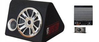
To connect a subwoofer to a radio with an amplifier, you need to prepare the necessary components and tools. First, the location where the low-frequency system will be located is determined. Most often, the luggage compartment of a car is used to install a low-frequency unit. The low-frequency vehicle channel complex includes the following components:
- Car radio
- Battery
- Low frequency amplifier
- High capacity capacitor
- Bass powerful speaker
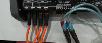
All these elements must be properly connected to each other. Power is supplied to the car radio in the standard way, so there is no need to change anything here. An important part of the installation of a low-frequency complex is the organization of power supply. The connection diagram for a subwoofer and an amplifier includes sending a sound signal from the car radio, connecting the power supply terminals to the battery and connecting the ULF output contacts to the speaker system. A low-frequency amplifier for a car is not like a household appliance. Usually this is a flat block in a metal case, on one of the walls of which there are coaxial “Tulip” type connectors for supplying an audio signal from an external source and screw terminals for connecting the supply voltage and speakers. In the connection diagram for the amplifier and subwoofer, a high-capacity capacitor is connected in parallel to the power terminals. It can be 0.5-2.0 farads. The storage capacitor functions as an additional power source.
When listening to music programs at high volumes, “dips” in the sound of the low-frequency system often occur. This is due to the fact that a car battery, at the peak power of a music system, cannot provide a large current consumption. In this case, the electrical energy stored in the capacitor is transferred to the ULF power supply circuit, ensuring normal sound. The amplifier and subwoofer are connected using a special cable designed for speaker systems. To connect elements of a low-frequency car kit, you cannot use ordinary SHVVP type wires from household equipment.
Kenwood
According to the instructions for this type of device, you can see the same standard connection diagrams as described above. The radio is connected via adapters.
If no car radio has yet been installed in your car, the connection diagram for the Kenwood radio remains the same, but you need to extend the speaker wire to the speakers. In this case, you need a stranded wire with a cross-section of at least 2 sq. mm. The wires must be insulated with heat-shrinkable casings or specialized terminals for clamps. The cables are pulled in accordance with the pinout given in the instructions. It is not permissible to connect a consumer with more than 300 mA to the blue (or white with a blue stripe) antenna power wire, intended for powering active antennas.
Sanyeng Kuron
To connect the radio to Sanyeng Kuron you will need a Daewoo Lanos - ISO adapter. The wiring diagrams for the radio tape recorder at Sanyeng Kuron are very standard. The main difficulty when changing a standard device arises only in the mechanical part of the removal. After which the wires of the stationary radio are disconnected, and the wires from the new head unit are connected through the Euro adapter.
Mystery 909u has a standard ISO connector. The Mystery 909u connection diagram involves connecting to a 12V source with a minus to ground. The power wires are connected through fuses. The black wire goes to negative ground.
Sources:
https://avtozvuk-info.ru/shemy-podklyucheniya-akusticheskoj-sistemy/podklyuchenie-avtomagnitoly/shema-podklyucheniya-avtomagnitoly-kenwood-76 https://www.elektrik-avto.ru/publ/avtozvuk/podkljuchenie_magnitol_kenwood/21 -1-0-568 https://electroshemi.ru/news/podkljuchenie_avtomagnitol_kenwood/2013-12-26-25 https://omagnitolah.ru/podklyuchenie/raspinovka-kenwood.html https://autotuning.expert/magnitola/ raspinovka-kenvud.html https://1avtozvuk.ru/podkluchenie/shema-podklyucheniya-provodov