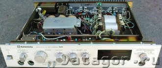
Repair of sound equipment Radiotekhnika U-7101S
Designing audio frequency amplifiers is a fairly pressing task, despite the wide range of offers of similar equipment from reputable and lesser-known companies. This is confirmed by the holding of annual exhibitions on this topic.
The high technical characteristics of the devices presented at these exhibitions, made on various, sometimes very exotic radio components, make it difficult to prefer any exhibit due to the fact that subjective assessments, as a rule, are influenced by various acoustic systems. Subjective perception largely eliminates the elemental base of radio components and circuits of these devices, but the preference for using modern high-quality semiconductor devices in them is obvious.
However, at present, the population still has a certain assortment of amplification devices produced during the Soviet era, with performance characteristics decent for that time. The current availability of modern components makes it possible to eliminate bottlenecks in these products when using them and makes it possible to modernize equipment with higher quality.
It should be noted that replacing individual elements in the equipment is ineffective. It is more rational to carry out modernization using blocks or assemblies with known characteristics. This approach, used in computer technology, allows for a quick comparison (by ear) of the proposed changes and drawing conclusions about their feasibility without considering and evaluating graphs, oscillograms and technical characteristics.
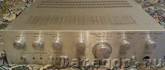
Naturally, the units being compared must be pre-established. Based on this concept, the “Radiotekhnika U-7101S” amplifier was repaired, which today is a very successful device for modernization [1]. It is a modification of the “Radiotekhnika U-101 S” amplifier, which was produced earlier. The main changes during its modification were made in the tone block, where out of three K157UD2 microcircuits only one was left and the oxide capacitors in the signal path were replaced with film ones; this had a positive effect on the sound quality.
A completely acceptable appearance and the presence of a number of necessary components are the basis for achieving a more successful result. During the modernization, significant improvements to the hardware and extremist solutions were not initially planned in order to obtain an output power of hundreds of watts. This amplifier is for home, where power up to 40...50 W per channel is sufficient when working with speakers with a sensitivity of 85...86 dB/W/m.
By modern standards, the technical characteristics of this amplifier (nominal output power - 2x20 W, harmonic distortion - 0.3%) are very modest, and the output stage plays a significant role in this. Attempts to improve the performance of the amplifier have been made previously [2]. Without entering into polemics with the author of these proposals, I would like to note that the use of a complementary pair KT805/KT837 in the output stage is not the optimal solution.
According to technical data, KT837 transistors have a cutoff frequency of the current transfer coefficient in a circuit with a common emitter of about 1 MHz. The KT818 and KT819 transistors released later were a little better and had this parameter slightly higher - 3 MHz. Therefore, replacing the KT805/KT837 pair with KT818/KT819 did not lead to a significant improvement in quality, which was subsequently noted by this author.
The characteristics of the power amplifier in the device can be significantly improved by implementing the circuit and design of the SymAsym5 2 UMZCH [3]. In this case, the following amplifier parameters are declared: output power - up to 60 W, harmonic distortion - up to 0.002% at the appropriate supply voltage and load. Modern semiconductor devices, circuit design using two differential stages and optimal wiring of the printed circuit board make it possible to obtain the highest quality results in the UMZCH unit.
In Fig. 1 shows a diagram of this UMZCH block. The printed circuit board and photo of the mounted board are given in the original source [3]. For those wishing to repeat the design, I recommend taking a look at the developer’s website; there, in addition to recommendations on the components used, their types and possible replacements, there is a number of other information useful in the manufacture of the block. In particular, we can recommend selecting resistors R4, R5 with a resistance spread of ±1% in the load of the input stage.
The dimensions of the printed circuit board (Fig. 2) allow for the possibility of installing in place each of the replaceable blocks U4 and U7 [1]. The boards are fastened in the device using the existing brackets.
When setting up the manufactured boards of the new UMZCH, the precision of setting the quiescent current of powerful transistors was taken into account. Therefore, the domestic SP5-2 was used as a tuning resistor R17. The U6 protection board is installed in its regular place through threaded posts 20 mm high.
To check the quality of work, a control audition of the new UMZCH was carried out in comparison with the original amplifier unit, disconnected from the corresponding connectors. A significantly more preferable and natural sound was noted, especially in the high-frequency part of the spectrum.
To realize the full potential of the upgrade, the circuit and design of the amplifier power supply have been changed. The capacitances of the blocking capacitors on the UMZCH boards and in the power supply itself have been significantly increased, and changes have been made to the power supply of the remaining amplifier units. This made it possible to obtain a noticeable increase in output power and significantly reduce AC background and noise.
The diagram of the upgraded power supply is shown in Fig. 3. The capacitance of the oxide capacitors of the rectifier is selected from several available ones (C6-C13). The capacity of metal-film capacitors C5 and C14 (13 μF) is also made up of two parallel-connected capacitors K73-11 with a capacity of 6.8 μF at 160 V.
The input block of the amplifier U2 on microcircuits used for electronic switching of input signals from various sources, in addition to some disadvantages described in the literature, had one more property: it clearly responded to turning on and off the refrigerator located in the next room. Therefore, the input switching circuit was changed to the version (Fig. 4) using sealed relays RES49, version RS4.569.421 for an operating voltage of 22...36 V.
If a relay of this type is used for a different voltage, it is necessary to select resistor R1. The installation of the relay on the input block board is shown in photo fig. 5. The number of inputs used for signal sources has been reduced to two (electromagnetic pickup and universal input). Input connectors SG5 (ONTS-VG-4-5/16-R) are installed in place of the former output connectors, and new output spring clamps are installed in place of the dismantled input ones (Fig. 6). All connections to the necessary points on the board are made via overhead wire installation.
When upgrading the “input board” amplifier, block U1 (UPZ-15) was left unchanged. This was done to enable its auditory comparison with an external preamplifier-corrector of the EPU magnetic pickup. The presence of two input connectors in the amplifier allows this to be done quite quickly.
The amplifier's tone block is additionally shielded at the top and bottom with metal plates. Its power supply circuit is made using D814D zener diodes instead of dividers formed by resistors R31n R32. The signal circuits from its output to the input of the power amplifier are made of shielded wire.
Wiring the common wire in amplifying devices is quite a serious task. If you type the phrase “ground routing in an amplifier” into an Internet search engine, you can see the relevance of this topic. In the upgrade option I propose, the task is made easier by the fact that in the manufactured board of rectifiers and filters, all common wires approaching it are connected at one point (the geometric center of the board), and on the remaining boards all common wire connections remain unchanged.
Noise from the wires running from the mains switch to the transformer has been minimized. For this purpose, a new cable was made from twisted wires with a cross-section of 0.75 mm, on which a screen braid and a PVC tube were put on. The braid is connected to the housing near the network transformer. The second section of the cable is designed similarly - from the switch to the network connector. To protect against impulse noise, a 0.1 µF capacitor of 630 V is installed at the transformer’s network terminals. The PKN41-1 amplifier power switch has been replaced with an imported one of similar purpose and design, with a short operating stroke.
The K157UD2 chip used in the tone block of the amplifier is a seemingly outdated op-amp. In this regard, I conducted control auditions when replacing it with the popular NE5532 and OPA2132 op-amp microcircuits used in audio equipment. The comparison results did not show any advantages of their use, and sensitivity to network interference turned out to be higher.
Perhaps this was due to the way the tests were carried out, in which one of the K157UD2 op-amps was cut off in the tone block on the print side, and the one being compared was connected to the corresponding areas of the board using short wires. Therefore, it was decided not to replace the previous microcircuit. In Fig. Figure 7 shows a general view of the installation of the modernized version of the amplifier.
Prevention and modification of the Radiotekhnika U-101 amplifier
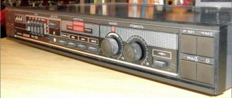
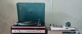
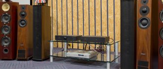
Hi all! I will not introduce this beautiful, legendary Soviet amplifier, but will immediately begin to describe the technology for working on it. The amplifier came into my possession in quite good external and working condition. The appearance of my U-101 Radio Equipment is presented in the photographs below.
Prevention.
First of all, we will talk about prevention. As is known, the most vulnerable element of electrical circuits, which depends on time, is the electrolytic capacitor. It dries out over the years and loses its capacity. Replacing all Soviet electrolytes with new, imported, pre-tested ones - this is the prevention of the Radiotekhnika U-101 amplifier.
Just for fun, I measured the capacity of two 5uF electrolytes that were on the power amplifier boards. I wasn't surprised because I expected it. Instead of 5 µF, the capacitance was about 30 nF, that is, the capacitances were completely dry. I checked the rest out of curiosity and was still surprised that the capacitors on the power supply board had a capacity greater than what was indicated on the can. Nowadays this rarely happens, especially with Chinese capacitors.
Next, I gradually replaced all the electrolytes, leaving the power supply board for later. On it I made several additional holes for mounting several capacitors. As a result, I doubled the capacity relative to the standard one, since the dimensions allow this to be done with a reserve, and there is no such thing as excess capacity. On the +-31V buses, I installed two electrolytes (in each arm), with a capacity of 4700 μF 50V each. And on the +-26V buses I installed two electrolytes (in each arm), with a capacity of 2200 μF 35V each.
I shunted the electrolytic capacitors of the power supply with film capacitors with a capacity of 100-470nF, one for each of the +-31V and +-26V arms.
After the preventive maintenance, the amplifier began to breathe in a new way, as if it had become 15-20 years younger.
Finalization.
Now I’ll tell you a little about the modification of the Radiotekhnika U-101 amplifier. Some craftsmen understand the word “rework” as a rework and throw out all the original guts from the case, but this turns out to be a completely different amplifier...
I will make a few minor changes that will improve the performance of the U-101 Radio Engineering.
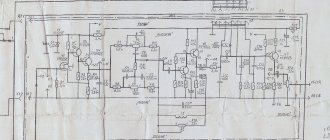
One significant drawback, which was implemented at the manufacturer's factory, is the unstabilized power supply of the tone control unit through quenching resistors R47 and R48 (see diagram). Quenching resistors are well suited in circuits with static loads (for example, for an LED). The tone block has a dynamic load. It is also necessary to take into account the fact that voltage ripple occurs on the +-31V buses at the rated power of the amplifier. Therefore, I added two integrated stabilizers LM7815 (+15V) and LM7915 (-15V), and instead of resistors R47 and R48 I installed jumpers. Thereby providing the tone block of the Radiotekhnika U-101 amplifier with a bipolar stabilized DC voltage of +-15V.
The next step was to replace the wires from the amplifier outputs to the rear panel with larger gauge wires.
The original Soviet fuse blocks were also replaced with imported ones. This is due to the fact that the fuses were not securely fixed in their original blocks.
Some connectors and terminals have been replaced by soldering to prevent loss of contact due to vibration.
In parallel with the network (primary winding), I installed a non-polar capacitor of type X2 with a capacity of 0.1 μF to suppress interference from the network (from the refrigerator, washing machine).
The next modification was to protect the signal wires running from the input board to the tone control unit from various interference, including 50Hz. To do this, I used a braid from a coaxial antenna cable. I placed a bundle of signal wires in two braids. Protected the screens with heat-shrinkable tubing. On one side (from the side of the input board) I brought out the lead from the screen (braids), and soldered this lead to the middle point of the power supply (grounded).
I also really wanted to replace the potentiometers, since over the years they wear out, and when adjusted they sometimes interfere. I wanted to, but it didn’t work out; unfortunately, I couldn’t find such potentiometers in my city.
However, the maintenance and modifications were successful, the amplifier remained the same and did not change inside. This is the same U-101 Radio Engineering that got its second wind.
The method for setting up the amplifier is described in the articles: “Setting the quiescent current of the Radiotekhnika U-101 amplifier”, “Setting the Radiotekhnika U-101 pre-amplifier”, “Setting the Radiotekhnika power level indicator”.
Amplifier circuit Radiotekhnika U-101