The L7805 CV integrated stabilizer is a conventional three-terminal 5V positive voltage regulator. Produced by STMircoelectronics, approximate price is about $1. Made in a standard TO-220 package (see figure), in which many transistors are made, however, its purpose is completely different.
In the marking of the 78XX series, the last two digits indicate the rating of the stabilized voltage, for example:
- 7805 - 5 V stabilization;
- 7812 - 12 V stabilization;
- 7815 - stabilization at 15 V, etc.
The 79 series is designed for negative output voltage.
Used to stabilize voltage in various low-voltage circuits. It is very convenient to use when it is necessary to ensure the accuracy of the supplied voltage; there is no need to install complex stabilization circuits, and all this can be replaced with one microcircuit and a couple of capacitors.
Connection diagram L7805CV
The connection diagram for the L 7805 CV is quite simple; to operate it is necessary, according to the datasheet, to place capacitors at the input of 0.33 μF and at the output of 0.1 μF. It is important during installation or design to place the capacitors as close as possible to the terminals of the microcircuit. This is done to ensure the maximum level of stabilization and reduce interference.
According to the characteristics, the L7805CV stabilizer is operational when supplying an input DC voltage ranging from 7.5 to 25 V. The output of the microcircuit will be a stable DC voltage of 5 Volts. This is the beauty of the L7805CV chip.
Specifications
In power supplies from a 220V network, a linear stabilizer is usually installed immediately after the rectifier diode bridge, where it performs its main role as a secondary power supply source (PSPS). The input voltage recommended by manufacturers for KREN8B is in the range of 14.5 ... 18 V. In any case, it should be 2.5-3 V more than the reference one.
Maximum parameters
Manufacturers declared the following maximum parameters for KR142EN8B, at case temperature (TC) from -45 to +70°C, unless otherwise specified:
- input voltage (at TC from -45 to +100°C) - up to 30 V;
- dissipation power – up to 1.5 W; up to 8 W (with heat sink);
- load current – up to 1500 mA (using a heat sink).
Electrical parameters
Typical connection
The stable operation of electronic devices is ensured by the stability of the power supply supplied to them. Hence the need to level it to the required level arises. Exceeding or decreasing the supply values is unacceptable, as it leads to malfunction of the equipment. The most obvious way is to use a popular domestic microcircuit from the KR142 series.
KR142EN8B is one of the linear stabilizers of this series. Its typical connection diagram is very simple and is suitable for all KR142EN. It includes the Krenka itself (another unofficial name 142EN8B) and a pair of smoothing capacitors. The datasheet recommends the use of small capacitors with values of 0.33 and 1.0 µF. Ceramic or tantalum versions are usually used.
If aluminum electrolytic capacitors are selected for the project, they must be at least 10 µF. It is better to connect them as close as possible to the pins of the microcircuit. Many radio amateurs do this by mounted installation, soldering the legs of the radio elements together.
Checking the functionality of the L7805CV
How to check the functionality of the microcircuit? To begin with, you can simply ring the terminals with a multimeter; if in at least one case a short is observed, then this clearly indicates a malfunction of the element. If you have a power source of 7 V or higher, you can assemble a circuit according to the datasheet given above and apply power to the input; at the output, use a multimeter to record the voltage at 5 V, so the element is absolutely operational. The third method is more labor-intensive if you do not have a power source. However, in this case, you will also receive a 5 V power supply in parallel. It is necessary to assemble a circuit with a rectifier bridge according to the figure presented below.
To check, you need a step-down transformer with a transformation ratio of 18 - 20 and a rectifier bridge, a further standard kit, two capacitors for the stabilizer and that’s it, the 5 V power supply is ready. The capacitor values here are overestimated in relation to the L7805 connection diagram in the datasheet, this is due to the fact that it is better to smooth out voltage ripples after the rectifier bridge. For safer operation, it is advisable to add an indication to visualize the device being turned on. Then the diagram will look like this:
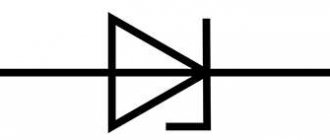
If there are a lot of capacitors or any other capacitive load on the load, you can protect the stabilizer with a reverse diode to prevent the element from burning out when the capacitors are discharged.
The big advantage of the microcircuit is its fairly lightweight design and ease of use, if you need power of one value. Circuits sensitive to voltage values must be equipped with such stabilizers to protect elements sensitive to voltage surges.
TL431 Specifications
Let's consider the maximum permissible performance characteristics of the microcircuit. If during its operation they are exceeded, the device will inevitably fail. Long-term operation with parameters close to the limit values is also not allowed. Let's look at them in more detail:
- cathode output voltage (VKA), relative to the anode terminal, up to 37 V;
- possible current values: for continuous cathode output (IKA) from –100 mA to 150 mA; for reverse input from -50 mA to 10 mA;
- typical impedance up to 0.22 Ohm;
- power dissipation (for different types of packaging) PD: 0.8 W (SOT-89); 0.78 W (TO-92); 0.75 W (SO-8); 0.33 W (SOT-23); 0.5 W (SOT-25);
- crystal temperature (TJ): operating: 0…+70 °C; -40 ... +125OS (for some car versions); maximum (TJmax) up to +150°C;
- body thermal resistance RθJC: 97OC/W (D); 156 OS/W (LP); 28 OS/W (KTP); 127OS/W (P); 52OS/W (PK); 149OS/W (PW);
- storage temperature: -65… +150 °C.
Recommended operating parameters
Characteristics of the L7805CV stabilizer, its analogues
Main parameters of the L7805CV stabilizer:
- Input voltage - from 7 to 25 V;
- Power dissipation - 15 W;
- Output voltage - 4.75...5.25 V;
- Output current - up to 1.5 A.
The characteristics of the microcircuit are given in the table below; these values are valid provided that certain conditions are met. Namely, the temperature of the microcircuit is in the range from 0 to 125 degrees Celsius, the input voltage is 10 V, the output current is 500 mA (unless otherwise specified in the conditions, the Test conditions column), and the standard body kit with capacitors at the input is 0.33 μF and at the output 0 ,1 µF.
The table shows that the stabilizer behaves perfectly when powered at the input from 7 to 20 V and the output will stably output from 4.75 to 5.25 V. On the other hand, supplying higher values leads to a more significant spread of output values , therefore, above 25 V is not recommended, and a decrease in input less than 7 V will generally lead to a lack of voltage at the output of the stabilizer.
When operating at heavy loads , more than 5 W, it is necessary to install a radiator on the chip to avoid overheating of the stabilizer; the design allows this to be done without any questions. Naturally, such a stabilizer is not suitable for more precise (precision) equipment, because has a significant spread in the rated voltage when the input voltage changes.
Since the stabilizer is linear, it makes no sense to use it in powerful circuits; stabilization based on pulse-width modeling will be required, but for powering small devices such as phones, children's toys, radio tape recorders and other gadgets. The domestic analogue is KR142EN5A or in common parlance “KRENKA”. In terms of cost, the analogue is also in the same category.
Source: instrument.guru
Specifications
The first versions (as can be determined from various datasheets on the 78L05) were developed in the 1970s by the American Fairchild Semiconductor. Their appearance resembled a regular transistor, since it had three legs and that’s where the similarity ended. Inside the small case was a marvel of engineering, containing a whole range of electronic components.
Marking
The marking encrypts minimal information about electrical parameters. The numbers “78” indicate positive polarity, then “L” - a small current (up to 0.1 mA) and “05” - voltage (up to 5 V) in the connected load. At the end of the designation there are symbols that determine the accuracy of stabilization, the operating temperature range and the type of housing.
Currently, many companies have mastered the production of complete copies of 78L05. With this designation it is produced by the Chinese Wing Shing Computer Components (WS). Modifications of the American Texas Instruments, Fairchild (LM78L05) and STMicroelectronics (L78L05) are mainly common on the world market. In Russia, the most common versions are from STM, and we will consider them in this article.
Tsokolevka
As you can see, the 78l05 (TO-92) pinout from WS is mirrored, which is why it differs from the STM and Texas Instruments standards. For many Chinese manufacturers it coincides with WS, for example Changjiang Electronics Tech (cj 78l05). It is worth considering this feature, as it may cause the circuit to fail.
Maximum parameters
In the vast majority of circuits, the L78L05 acts as a fixed voltage regulator of 5 V. Moreover, for its stable operation, 2-3 V more (from 7 V) must be supplied to the input than what is received at the output. If a good heat sink is provided, it can withstand an output current of up to 100 mA. Here is a list of the maximum parameters of this microcircuit.
- input voltage up to 30 V;
- output current up to 0.1 A;
- heating the crystal to +125°C;
- storage temperature -65 … +150С;
- power dissipation is limited by internal protection.
Electrical parameters
Electrical ratings for the L78L05 are based on a typical test setup. The “Test conditions” column indicates testing conditions at normal crystal temperature (TJ) up to 25 °C. It must be within acceptable limits, depending on the modification of the device. Below is a summary table of electrical parameters of the most common L78L05 series microcircuits.
A typical testing circuit contains 0.33 µF and 0.1 µF capacitors. This uses a voltage of VO=10 V. Unless otherwise specified, the output current of IO is 40 mA.
As can be seen from the presented data, the L78L05 differ slightly from each other in individual values. There are some features of the modifications that are worth noting. For example, if the symbol “B” is present in the designation, then the device is capable of operating at low ambient temperatures (from -40°C). L78L05A, with an additional letter “A” at the end of the marking, have an increased output voltage stabilization accuracy of ±4%. And for ordinary “C” this spread is twice as large and amounts to ±8%.
L7805-CV Linear DC Voltage Regulator
L7805-CV - for almost any radio amateur, assembling a power supply with a stabilizing output voltage on the 7805 microcircuit and similar ones from this series is not difficult at all. It is this linear input DC voltage regulator that will be discussed in this material.
The figure above shows a typical L7805 linear regulator with a positive polarity of 5v and a rated operating current of 1.5A. These microcircuits have become so famous that most of the world's companies have taken up their production. But in the picture below, the circuit is slightly improved, by increasing the capacitance of capacitors C1-C2.
As a rule, between radio engineers and electronics engineers this chip is called abbreviated, without naming the letters in front indicating the manufacturer. After all, it is already clear to everyone that this is a stabilizer, the last digit of which indicates its output voltage.
For those who have not yet encountered these electronic components in practice and know little about them, here is a short video on how to assemble the circuit for clarity:
Voltage stabilizer 5v! On the L7805CV chip
One of the important conditions is high quality components
In fact, when purchasing components, the manufacturer plays a significant role. When you purchase any electronic components, always pay attention to the brand of the part, and also ask who supplies it. Personally, I am satisfied with the products, a manufacturer of microelectronic components.
Unnamed stabilizers or from little-known companies, as a rule, always cost less than similar ones from well-known brands. But the quality of such parts is not always at the proper level; their operation is especially affected by a significant variation in the output voltage.
Manufacturers
Due to its good parameters, reliability and low cost, TL431 is used in various technical solutions. Therefore, many foreign companies are engaged in its production. There is even a fully translated datasheet tl431 in Russian from Texas Instruments (TI). Here are links to some datasheets of devices sold in the Russian Federation: TI, ON Semiconductor, STMicroelectronics, Nexperia, HTC Korea, NXP Semiconductors. There are still manufacturers of these products, but they are difficult to find in Russian stores. These include: Unisonic Technologies, Motorola, Fairchild Semiconductor, Diodes Incorporated, HIKE Electronics, Calogic, Sangdest Microelectronic (Nanjing), SeCoS Halbleitertechnologie GmbH, Hotchip Technology, Foshan Blue Rocket Electronics, etc.
Voltage regulator
A voltage stabilizer is the most important radio element of modern radio-electronic devices. It provides a constant voltage at the output of the circuit, which is almost independent of the load.
Stabilizers of the LM family
In our article we will look at voltage stabilizers of the LM78XX family. The 78XX series is produced in metal cases TO-3 (left) and in plastic cases TO-220 (right). Such stabilizers have three terminals: input, ground (common) and output.
Instead of “XX”, manufacturers indicate the stabilization voltage that this stabilizer will give us. For example, a 7805 stabilizer will produce 5 Volts at the output, 7812 will produce 12 Volts, and 7815 will produce 15 Volts. Everything is very simple.
Connection diagram
And here is the connection diagram for such stabilizers. This circuit is suitable for all stabilizers of the 78XX family.
In the diagram we see two capacitors that are sealed on each side. These are the minimum values of capacitors; it is possible, and even desirable, to supply a higher value. This is required to reduce ripple at both the input and output. For those who have forgotten what ripple is, you can look at the article on how to obtain a constant voltage from an alternating voltage.
Characteristics of LM stabilizers
What voltage should be supplied for the stabilizer to work as it should? To do this, we are looking for a datasheet for stabilizers and studying it carefully. We are interested in these characteristics:
Output voltage – output voltage
Input voltage – input voltage
We are looking for our 7805. It gives us an output voltage of 5 Volts. Manufacturers noted a voltage of 10 volts as the desired input voltage. But it happens that the output stabilized voltage is sometimes either slightly underestimated or slightly overestimated.
For electronic trinkets, fractions of volts are not felt, but for precision (accurate) equipment it is better to assemble your own circuits. Here we see that the 7805 stabilizer can give us one of the voltages in the range of 4.75 - 5.25 Volts, but the conditions must be met that the output current in the load will not exceed 1 Ampere. An unstabilized DC voltage can “fluctuate” in the range from 7.5 to 20 Volts, while the output will always be 5 Volts.
The power dissipation on the stabilizer can reach up to 15 Watts - this is a decent value for such a small radio component. Therefore, if the load at the output of such a stabilizer consumes a decent current, I think it’s worth thinking about cooling the stabilizer. To do this, it must be placed on the radiator through KPT paste. The greater the current at the output of the stabilizer, the larger the radiator should be. It would be generally ideal if the radiator was also blown by a fan.
LM work in practice
Let's look at our ward, namely the LM7805 stabilizer. As you already understand, at the output we should get 5 Volts of stabilized voltage.
Let's assemble it according to the diagram
We take our Breadboard and quickly assemble the connection diagram suggested above. The two yellow ones are capacitors, although it is not necessary to install them.
So, wires 1,2 - here we drive the unstabilized input DC voltage, remove 5 Volts from wires 3 and 2.
On the Power Supply we set the voltage in the range of 7.5 Volts and up to 20 Volts. In this case, I set the voltage to 8.52 Volts.
And what did we get at the output of this stabilizer? 5.04 Volts! This is the value we will get at the output of this stabilizer if we supply voltage in the range from 7.5 to 20 Volts. Works great!
Let's check one more of our stabilizers. I think you have already guessed how many volts it is.
How to make a power supply for 5, 9.12 Volts
How to make a simple and highly stable power supply for 5, 9 or even 12 Volts? Yes, very simple. To do this, you need to read this article and install a stabilizer on the radiator at the output! That's all! The circuit will be approximately like this for a 5 Volt power supply:
Two electrolytic capacitors to eliminate ripple and a highly stable 5 volt power supply at your service! To get a power supply for a higher voltage, we also need to get a higher voltage at the output of the transformer. Aim for the voltage on capacitor C1 to be no less than in the datasheet for the stabilizer being described.
To ensure that the voltage stabilizer does not overheat, apply the minimum voltage specified in the datasheet to the input. For example, for the 7805 stabilizer this voltage is 7.5 Volts, and for the 7812 stabilizer the desired input voltage can be considered a voltage of 14.5 Volts. This is due to the fact that the voltage difference, and therefore the power, the stabilizer will dissipate on itself.
As you remember, the power formula is P=IU, where U is voltage and I is current. Consequently, the higher the input voltage of the stabilizer, the greater the power consumed by it. And excess power means heating. As a result of heating, such a stabilizer may overheat and enter a protection state, in which further operation of the stabilizer stops or even burn out.
How to check all voltage stabilizing devices with a multimeter
Voltage stabilizers are electronic devices with a complex structure, which means they have different operating problems and possible malfunctions. There are various incidents in their work that are associated with the greatest loads, and there are also real breakdowns. These concepts should be distinguished, for which there are several tips.
First of all, let's look at how you can perform a quality check of the operation of this device. The most reliable method of monitoring the quality of a device is a conventional voltmeter, which can measure the voltage in the apartment network, as well as the voltage at the output of the device. In a home outlet, the voltage can fluctuate in the range of 170-240 volts, and at the output of the stabilizing device it should be equal to 220 volts.
But not everyone uses a simple method of checking the operation of a voltage stabilizer, since they trust the data from the indicator. But this trust is not always justified, and sometimes on Chinese devices the digital indicator is simply connected directly to the relay. In this case, the relays have a fairly large step, and it will always show 220 V. In fact, the output will have a completely different value.
Manufacturers
The original L78 devices are manufactured by the European company STMicroelectronics (STM), which is constantly improving the quality of its products.
The latest versions of the device from the named company are certified by ECOPACK. They comply with international eco-standards. Since the device has enough analogues, and it is sold at an adequate price, up to approximately 50 rubles, counterfeits are almost impossible.
How to check the electrical stabilizer
This check is quite simple. To do this you need to take the following devices:
- Two table lamps.
- Stabilizer.
- Electric stove.
- Power extension cord with 3 sockets.
- Insert the extension cord plug into a household outlet.
- Connect the stabilizer to an extension cord.
- Connect a 60 W table lamp to the stabilizer.
- Connect the electric hotplate to the extension cord.
If the stabilizer functions normally, then the operation of the tile will not affect the light of the light bulb, but if the lamp is connected directly to the extension cord, then when the tile is turned on, the light will become weaker. This is explained by the fact that a powerful consumer in the form of a tile significantly reduces the voltage and the lamp connected to the network before the device will produce less light. But a lamp powered after a voltage stabilizer will not respond to increased load.
It also happens that people do not understand the work of the stabilizer and complain about its poor performance, although this is not the case at all. This happens in such a way that the stabilizer de-energizes the load unexpectedly when washing clothes in an automatic machine. But there is no fault with this. An automatic washing machine is a powerful consumer of electrical energy, but its power is distributed unevenly. When heating water, the power can reach up to 5 kW, and during normal washing it decreases to 2 kW. From high school physics lessons we know that if you reduce the voltage at the input of a transformer and increase the voltage at the output, the output power will also decrease significantly. See the article about a stabilizer for a washing machine.
Therefore, a situation may arise that when the voltage at the output of the voltage stabilizer decreases, the power will be sufficient to rotate the drum, but not enough to heat the water. In this case, it is necessary to turn off all unnecessary consumers and pour separately heated water into the machine.
Check procedure
The whole process comes down to how the diodes are tested. This is done with a conventional multimeter in resistance or diode testing mode. A working zener diode can conduct current in one direction, similar to a diode.
Let's consider an example of checking two zener diodes KS191U and D814A, one of them is faulty.
First we check the D814A diode. In this case, a zener diode, by analogy with a diode, passes current in one direction.
Now we check the KS191U zener diode. It is obviously faulty, since it cannot pass current at all.
Probe circuit for checking the KREN microcircuit
This scheme is inferior to the previous layout.
Capacitor C1 removes generation when the input voltage is connected in steps, and capacitor C2 is designed to protect against impulse noise. We take its value to be 100 microfarads, the voltage according to the value of the voltage stabilizer. The 1N 4148 diode prevents the capacitor from discharging. The input voltage of the stabilizer must exceed the output voltage by 2.5 V. The load should be selected in accordance with the stabilizer being tested.
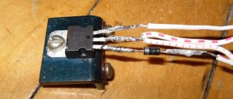
The rest of the probe elements look like this:
The contact pads became the mounting location for circuit elements. The body turned out to be compact.
A power button was installed on the case for ease of use. The pin contact had to be modified by bending.
At this point the sampler is ready. It is a kind of attachment to a multimeter. We insert the probe pins into the sockets, set the measurement limit to 20 V, connect the wires to the power supply, adjust the voltage to 15 V and press the power button on the probe. The device worked, the screen displays 9.91 volts.
Source: ostabilizatore.ru
TL431 connection diagrams
Let's figure out how the TL431 works using the example of a simple stabilization circuit, consisting of a zener diode itself and one resistor. The positive pole of the power supply is connected to the cathode, and the negative pole of the power supply is connected to the anode. To turn on the microcircuit, a reference voltage (Vref) is applied to its control electrode.
If its value is more than 2.5 V, then the zener diode will almost immediately open and begin to pass current through itself (IKA), which can be used to power the corresponding load. Its value will increase as the Vin level increases. IKA can be determined by the formula IKA = (Vin—Vref)/R. In this case, the output voltage of the circuit will be stabilized at the reference level (VKA = Vref), not exceeding 2.5 V and regardless of the Vin supplied at the input.
Calculation of a parametric stabilization scheme
To obtain a higher voltage at the output of the microcircuit (up to 36 V), a resistive divider is additionally connected to its control electrode. It consists of two resistors (R1 and R2) connected between the cathode and anode. In this case, the internal resistance of the zener diode increases by (1 + R1/R2) times.
To calculate the stabilization circuit on the TL431, initial data on the input (VIN) and output (VKA) voltages, as well as currents: stabilization (IKA) and load (IL) are required. With this data, you can calculate the values of other electronic components shown in the figure below.
The output voltage and resistance ratings are related to each other by the following formula VKA= Vref *(1 + R1/R2)+ Iref *R1. Where Vref = 2495 mV and Iref = 2 µA are typical values, they are indicated in the electrical parameters from the datasheet for the device.
Resistance R1 can also be taken from the datasheet. Most often they are taken with ratings from 10 to 30 kOhm. The value of R1 is limited by the small reference current (Iref = 2 µA), which is often neglected for calculations of stabilization circuits on the TL431. Therefore, to calculate the value of R2, without taking into account Iref, you can use the following formula R2=R1/((VKA/Vref)-1).
Stabilization voltage adjustment
To build circuits with the ability to manually adjust the output voltage, a potentiometer is installed instead of the usual R1. The value of the limiting resistor R, which resists the current at the input (IIN), is calculated using the formula R = (VIN-VKA) / IIN. Here IIN = IKA+ IL.
Despite the advantages of the TL431 microcircuit, it also has a very significant drawback - it is a small load current that it can withstand. To solve this problem, powerful bipolar or field-effect transistors are included in the circuit.
Examples of various circuits based on the TL431 zener diode can be seen in the following video.
HOW TO CHECK THE STABILIZER CHIP
It was necessary to assemble input stabilizing power supply circuits for a device based on the PIC16F628 microcontroller that operates stably at a voltage of 5 volts. It is not difficult. I took the PJ7805 integrated circuit and made it based on it in accordance with the circuit from the datasheet. I applied voltage and got 4.9 volts at the output. Most likely, this is quite enough, but stubbornness, mixed with pedantry, took over.
I took out a box of integral stabilizers and set out to try on all the corresponding ones. And so as not to make a mistake, I even laid out the corresponding diagram in front of me. However, the enthusiasm ended already at the very first component. This “hedgehog without arms, without legs” made of connecting wires with crocodiles wanted to live his own life and obeyed the will of the radio amateur with great difficulty. Moreover, the tested stabilizer at the output showed 4.86 volts, which plunged my optimism into despondency.
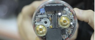
No, something more significant is needed here, for example, some kind of albeit simple, but nevertheless a sample or something. I typed it into the Yandex search engine and got what you see in the photo “Complex for monitoring integrated voltage stabilizers.” Well, this is not for the average amateur radio mind. It became clear that the wheel would have to be reinvented.
Component quality
In reality, the manufacturer is very important. Always try to buy stabilizers, and any parts from major manufacturers and trusted suppliers. I personally prefer STMicroelectronics. They are distinguished by the ST emblem in the corner.
Noname stabilizers or those produced by Chanhanbzdyun's grandfather very often have a significant variation in output voltage values from product to product. In practice, it was found that the 7805 stabilizer, which should give 5 volts, gave 4.63, or some samples gave up to 5.2 volts.
It would be fine, it keeps the voltage constant, but the problem is that the emissions and background are several times stronger and the consumption of the stabilizer itself is greater. I think you understand.