↑ Golden ratio
A person distinguishes objects around him by their shape.
Interest in the shape of an object can be dictated by vital necessity, or it can be caused by the beauty of the shape. The form, the construction of which is based on a combination of symmetry and the golden ratio, contributes to the best visual perception and the appearance of a feeling of beauty and harmony. The whole always consists of parts, parts of different sizes are in a certain relationship to each other and to the whole. The principle of the golden ratio is the highest manifestation of the structural and functional perfection of the whole and its parts in art, science, technology and nature. Many argue that objects containing the “golden ratio” are perceived by people as the most harmonious. Fragment excluded. The full version is available to patrons and full members of the community.
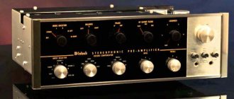
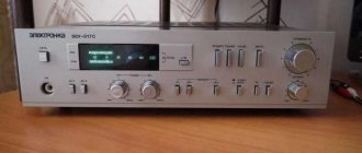
Let me note a few points. The volume knob should be approximately 2/3 of the width of the front panel. Place at a distance of 1/5 from the edge. On the right (I'm right-handed). The power switch is on the opposite side (controls with different purposes must be separated). The level indicator is also on the left, it also acts as a power indicator. In the middle there is a final link - a label (or nameplate, plate, as you like)
Back panel:
At the back, on the right, there is a power connector and a fuse. On the left are the input and output jacks. This is what I want to get. We will strive for this.
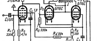
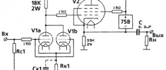
Circuit of a homemade tube amplifier (ULF)
The diagram is taken from the website heavil.ru
I must say that the scheme is probably not the best, but due to its relative simplicity and availability of parts, I decided to stick with it. Output transformer (an important figure in the plot).
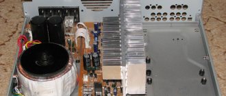
It was decided to use the “legendary” TS-180 as output transformers. Don’t throw stones right away (save them for the end of the article ) I myself have deep doubts about this decision, but given my desire not to spend a penny on this project, I will continue.
I connected the trance outputs for my case like this.
(8)—(7)(6)—(5)(2)—(1)(1′)—(2′)(5′)—(6′)(7′)—(8′) primary
(10)—(9)(9′)—(10′) secondary
anode voltage is applied to the connection of pins 1 and 1′, 8 and 8′ to the anodes of the lamps.
10 and 10′ per speaker. (I didn’t come up with this myself, I found it on the Internet). To dispel the fog of pessimism, I decided to check the frequency response of the transformer by eye. To do this, I quickly assembled such a stand.
In the photo there is a GZ-102 generator, a BEAG APT-100 amplifier (100V-100W), an S1-65 oscilloscope, a 4 Ohm load equivalent (100W), and the transformer itself. By the way, the site has an online calculator that calculates the resistor for connecting an LED.
I set it to 1000 Hz with a swing of 80 (approximately) volts and record the voltage on the oscilloscope screen (about 2 V). Next, I increase the frequency and wait until the voltage on the trance secondary starts to drop. I do the same thing in the direction of decreasing the frequency.
The result, I must say, pleased me: the frequency response is almost linear in the range from 30 Hz to 16 kHz, well, I thought it would be much worse. By the way, the BEAG APT-100 amplifier has a step-up transformer at the output and its frequency response may also not be ideal.
Now you can collect everything in a heap into a case with a clear conscience. There is an idea to do the installation and layout inside in the best traditions of so-called modding (minimum wires in sight) and it would also be nice to have LED backlighting like in industrial copies.
↑ Schematic diagram
Amplifier circuit 1 channel
Fragment excluded. The full version is available to patrons and full members of the community.
Power supply diagram
Fragment excluded. The full version is available to patrons and full members of the community.
The circuit diagram is chosen in a classical manner and consists of two cascades. Preliminary SRPP on 6Н9С and final on 6С4С. In the preliminary stage, it was not without reason that I used the inclusion of lamps with dynamic loads. The fact is that turning on the lamp in this way ensures simultaneous improvement of several important parameters: linearity, broadband, mode stability, output resistance, overload capacity and sensitivity to anode voltage pulsations. And it provides the necessary gain to drive 6C4C, with a grid offset of -45V.
High power resistors are used in the cathode circuit of the output stage. Resistors R7 and R10 24 Ohm. it is necessary to select so that the potential relative to ground at terminals 2.7 of the 6C4C lamp is the same and equal to approximately +46 V. One option is to use a 50-100 Ohm variable resistor instead of R7 and R10. 5 W.
After assembly, the amplifier starts working immediately. Setting up the amplifier comes down to adjusting the parameters indicated in the diagram. If the current and voltages are not as shown on the diagram, the lamp will most likely need to be replaced.
Lamp incandescence
of different cascades is made separately, from different windings of the power transformer. In addition, the 6S4S filament is made with constant voltage. This is necessary to reduce the background level. Mixing resistors R1 and R2 (power supply circuit) serve the same purpose. Anode power is removed from one winding for both channels. An LC filter is used in the circuit. For decoupling between channels, a separate choke is installed on each.
Signal strength indicator
assembled on a
6E5C
according to the classical scheme. The input is connected to the anode of the 6S4S output lamp. To prevent the lamp rays from twitching wildly in time with the music, a VD2 diode is introduced into the circuit, which cuts off the half-cycle of the input signal. Thus, ensuring smooth beam travel. Variable resistor R2 adjusts the sensitivity of the indicator.
Indicator diagram
The lamp panel is fixed at an angle of 90 degrees. to the chassis, on a bracket brazed from foil fiberglass.
Anode Feed Delay
is an elementary circuit using a single transistor. Printing board
In this circuit, the voltage across the relay coil increases slowly. With the given capacitor values, the delay is about 2 minutes. You can reduce the time by lowering the capacitance of capacitor C5. During operation, I encountered a problem: with a smooth increase in voltage, the relay does not close the contacts even when the voltage reaches the nominal value. I made a delay of about 15 seconds. Output transformer
overall power 100 W.
Ktr.=24 Ra=4. I took ready-made sound transformers. Therefore, I do not provide data on winding. Power transformer
TOP with overall power of 200 W. I had one with one secondary winding at 210 V. 0.7A. I had to wind up an additional 3 windings. 6.3 V. 2.5 A. – Heating of output lamps 6С4С; 6.3 V. 200 mA. – Heating of the preliminary stage lamps 6N9S; 9 V. 200 mA. – Anode feed delay relay.
Tube amps are not bad. Let's add some common sense, part 4
Continuation of the article based on materials from the Internet electronic network with reflections from Yuri Ignatenko’s “Notebook” and my comments and amendments
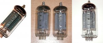
Radio tubes.
At the first stage of approaching a project, you need to decide on the main thing. You should understand which output transformer the amplifier is made for (for which acoustics).
From here it is easy to understand and choose which lamps the UMZCH will use. You should take into account the availability and cost of high-quality panels. On octal or finger? And select the type of output lamps: 6P1P, 6P14P, 6P6S, 6P3S, 6P13S, 6P31S, G807, 6P36S, 6P41S, 6P42S, 6P44S, 6P45S. It is not advisable to make an amplifier on a 6P43P; it easily warms up. Lamps 6P15P, 6P18P are also relatively low-voltage lamps. And an amplifier of increased efficiency reveals dynamics when there is over 300 volts at the anode. In this case, a larger amplitude can be obtained on the primary TVZ. In the driver you can use 6Zh1P, 6N1P, 6N2P, 6N23P, 6N8S, 6N9S, 6Zh4, 6Zh8, 6G2. 6Zh7, 6G7 are also possible, but they have a cap on top, which is inconvenient. I usually do 6N2P, 6P14P or 6N9S, 6P6S. It should be remembered that the vacuum tube must be in proper storage, the vacuum must be maintained. It is unacceptable to use soaked and frozen 50-year warehouse stocks. Cloudy cracked glass, damaged dangling bases, chipped and broken legs, an unclear getter are signs of unsuitable lamps. The output tube is a powerful amplifier element. It doesn't matter what type it is. Here preferences are mainly aesthetic or marketing. Technically, it is much more important what kind of output transformer is available. An appropriate reinforcing link should be selected for it. The most important question is how to bring the mode of the used lamp in accordance with its datasheet; skill and qualifications are important here. Serviceable Sovdepov lamps are in no way inferior to imported ones. If a vacuum is ensured, then it makes no difference whether the vacuum inside is American or communist. And the amount of gold and platinum inside the lamp does not affect the sound in any way, but only determines the damage to the buyer’s wallet and the disposal cost of the light bulbs.
The power in class A that any lamp can produce is approximately calculated this way. Knowing the parameters of the output stage Ua x Ia = 21 watts, divide by THREE = 7 watts. The 6P3S lamp holds 380 volts 40-55mA. The more U, the better, they sound great. For 6P3S - if the anode voltage is increased to 300-320 volts, then this will be quite normal. The cathode current must be set to 55mA by selecting a cathode resistor. Nothing will happen to a working lamp. You just need to not exceed the parameters leading to reddening of the anode. The 6P3S lamp works normally at 350-400 volts at the anode. At the same time, it does not get hot and works for years in pop amplifiers. The anode voltage recommended for 6P3S in push-pull should be no less than 350 volts.
Note. TV viewers should remember that exceeding the permissible anode voltage for a vacuum tube is relatively safe. But significantly exceeding the permissible anode current should be avoided. Evgeniy Bortnik
Two 6P3S lamps should not be paralleled in one cycle. There are no perfectly identical lamps, so one lamp will work with a large Ku and with a more significant current, and the second will cause distortion. For a 6P6S lamp in mode A, the cathode current should be 50-57mA. This mode is set either in one-cycle or in two-cycle. The 6P7S lamp is close to the G807, but with a base like the 6P3S and 6P9 it is an excellent lamp. On one ULF lamp the maximum will be 2 Watts. The gain of this lamp is under 100, so the circuit does not require a pre-amplification lamp. Lamp 6P14P is an analogue of EL84 - you can use up to 350 volts at the anode and it will be fine. And the dissipation power of this lamp can be exceeded by a factor of 1.3 (practically tested). When the lamp is put into the permissible high voltage mode, then the amplifier will sound. At an anode voltage of 250 volts, a 6p14p light bulb will sound like a “dead” bulb and its mode is more difficult to reconcile with a standard TVZ.
When you first turn on the amplifier, the anode current in the 6P14P should be set to 45mA immediately, and not wait until the lamp gets hot and then you can increase it. Full mode A in 6P14P with good sound is achieved with a cathode current of 50-55mA. Moreover, mode A is 42 mA and 50 mA and 55 mA and 60 mA. But the sound gets better and better as the current through the output tube increases. You need to look and find a practical compromise in the amplifier, between the reliability of the output tubes and the maximum permissible current. The correct mode is sought practically. Experts have long found the limiting modes of output lamps. They do not correspond to the datasheets provided by the factories. They can be called compromises, on a fine line between sound quality and reliability. If such experiments frighten you, then you should not do them. It is quite enough for you to assemble a 2-4 watt amplifier using 60 watt lamps and 20 kilogram transformers and be proud of the result achieved. This is your real ceiling.
Lamps 6P31S, 6P13S have an anode voltage of at least 300 volts, although the lamps are different. The characteristics of 6p13s are significantly better. As the current increases, the voltage will drop slightly on the TVZ and on the cathode resistor. However, with such power supply and high-quality components there is nothing to fear. These lamps sound good. The disadvantage is the upper location of the cap. The 6P13S lamp costs only 4 hryvnia, and it swings very easily and the sound is simply excellent.
The G807 lamp is high-voltage and requires an anode voltage of 500 volts. Therefore, with 25 watts of power dissipation, the current will be approximately 50mA. Practice has shown that it is possible to increase it to 70mA without harm. And get an additional 8-9 watts of useful power. However, here a higher quality TVZ is needed; filter capacitors are needed for 700-800 volts. G807 is easily driven by one triode (6N2P, 6N9S). EL34 lamps also require up to 500-600 volts. The GU50 lamp operates at voltages of more than 600-800 volts at the anode, with cathode currents of 50-60 mA. This is not a current lamp, but a lamp with which higher voltages are preferred, like the G807.
GU17 is firewood, I don’t recommend paralleling or using it at all. Even in special equipment, the failure of its design is gradually recognized.
The 6P41S lamp is a current lamp, so many theorists believe that the anode voltage for it should be low. But there are high-voltage ULF modes for it, which can be verified both by ear and by instruments. The lamp opens perfectly at 310 volts anode and 70 mA. The IMD is reduced by 10 times compared to 250 volts of the anode. With the same output power of 8 watts. Its operation is also permissible at 320-340 volts. The anode voltage is 320 volts, the grids are also 320 volts, and UL mode with a cathode current of 70-80 mA. The bias is -50 volts. According to papers, the power dissipated at the anode of the 6P41S is only 14 watts. And a two-stroke on a 6P41S in class A produces 20 W. And it dissipates, for example, in a single cycle in class A at 340 volts more than 25 W. The dimensions of the cylinder allow such modes. In all discussions about the permissible overload of lamps, it should be remembered that the glass cooling conditions must be good. And increased voltages are supplied to the anode after warming up the cathodes, by first applying filament voltage with a separate toggle switch, or by using an automatic delay in the supply of anode voltage. Remember, increased wear of lamps, as well as premature aging of lamps, occurs not so much due to the use of extreme operating conditions. Often the cause of their wear is poisoning of the cathodes due to poor heating or its delay. But failure occurs more often with an unacceptable voltage pulse at a cold cathode. However, this is very rare, since working lamps are quite reliable.
Question. One of the graphs for RR on 6P41s shows a mode of 350V*70 mA. In this case, R anode = 24.5 W. Seems like a bit much. Can you recommend this mode as a working mode or is it only for research?
Answer. This is a proven operating mode for a working lamp. Several designer amplifiers already work with such modes for music lovers. In practice, you can increase the dissipated power until the anode turns red, this will be 100mA and then carefully reduce it to 70mA. The 6P44S beam tetrode gives excellent results, but this requires at least 270 volts.
6P43P is a current lamp for vertical scanning. Objectively weak and operates at lower anode voltage and higher current. Anode voltage no more than 220 volts. Increasing the voltage to 300 volts often leads to self-heating of the lamp. To limit the current, you need to install a 340-400 Ohm auto-bias resistor in the cathode. This lamp has low internal resistance and therefore requires a non-standard TVZ. It should be remembered that this lamp does not replace 6P14P in any way.
Lamps 6S33S, 6P42S, GM70 are current lamps with a large input capacitance. To drive them, in addition to the triode (1/2 6N9S), you need a cathode follower (second stage). For 6S33C, the self-heating mode can be frantic when the dissipated power exceeds 35-40 W. Protecting the anodes with a 0.5 ampere fuse often does not help. 6С33С is a very effective lamp, giving excellent results in triode push-pull. But you need to be very careful with it, using auto-bias, sequential bias according to A. Torres, or more complex tracking circuits. The efforts will pay off in spades, the dynamics of push-pull amplifiers on the 6S33C are simply monstrous, and the selection for a load of 80-100W is realistic. It's like a powerful Rolls Royce on the road in Uryupinsk. But you can limit yourself to selecting 10 watts from it in complete safety and be proud of yourself again.
There is a feeling that no one has tamed the dual triodes 6N5S, 6N13S yet. This is because the current-voltage characteristics of lamps are really unsuitable. They are extremely nonlinear, and the halves of the lamps are in practice asymmetrical. Such lamps are more suitable for voltage regulators. To use them in LUMZCH, special measures for automatic balancing of the halves are required. Projects using their doubling are possible. It is still not recommended to squeeze maximum power out of them, although it is quite possible to build a powerful two-stroke. 6N13S lamps look very good!
I do not recommend using directly heated lamps of type 2A3. If you haven't made claw amplifiers before, just beware. A direct filament lamp is not so easy to defeat. Acceptable quality UMZCH requires a low background alternating current. No one has yet really overcome the background in direct heat. There is a feeling that direct-heating is a whim and a dead-end branch in amplifier construction. Don’t believe the fairy tales written on the Internet; these light bulbs are very easy to give you hemorrhoids. If directly heated lamps were better than indirectly heated lamps with cathodes, then manufacturers would never have switched to the production of the latter. Direct heating was relevant only in the age of battery-powered devices. The directly heated lamp was easier to manufacture, cheaper, and had lower filament current consumption. Although direct heating is inferior in all respects to indirect heating. Answer yourself clearly the question: Why such torment? To get 2 measly watts at the direct-heat output at a 5kOhm load?
Question. Which tubes, octal or finger-type, are best for assembling an amplifier?
Answer. There is a natural dependence of the output power on the size of the anode. A larger anode cools better. After all, there is a vacuum inside the flask and cooling occurs only by radiation of heat onto the glass and then through the flask into space. For small finger lamps, the maximum size of the cylinder and anode is the 6P14P lamp. And octal and other larger glass lamps have a larger anode and allow them to exceed operating parameters by 1.5-2 times without overheating and reddening of the anode. Remember that a high-quality amplifier can be made using any tube. First understand the topic of output transformer. And then focus on output lamps with a current of at least 50mA. Good 75mA 6P41S and excellent 100-140mA 6P36S, 6P45S. At the very first stage, we can recommend building a two-stroke on 6P3S. This is perhaps the most successful domestic light bulb.
Question. Will the 6E5P pentode drive the 6P43P output tube?
Answer. If, for example, you are swinging 6P36S, 6P45S, then it is recommended to use 6Zh8 or 6Zh4 pentodes. This is because good swing is needed for heavy lamps. And to pump up the 6P43P, a weak triode is enough.
Question. Is it possible to parallel 6P7S in a single cycle? How much power can be removed from them in a single cycle without compromising quality?
Answer. In single-cycle, lamps should not be placed in parallel in principle. I had to make such an amplifier, the customer insisted and sent lamps. But there are no lamps with identical branches of the current-voltage characteristics, and one lamp will always lead and the other will catch up. Nothing good will come of it. This option is not suitable for a high-quality, high-performance amplifier. You need to make a push-pull amplifier, not a single-ended one with parallel tubes. It is significant that single-ended amplifiers were not mass-produced in the world. Commercial manufacturers produced only two-strokes. In receivers, starting from the first class, push-pull was already used. In higher-class tape recorders, push-pull switches were already used. Single-cycle is suitable for getting acquainted with tube sound, it’s dead in a word, as long as it plays. According to the laws of development and growth, the transition to two-stroke still follows. Push-pull 20-30 watt output power is another matter. It sounds decent and has dynamic range. And a single-cycle on 6P7S is 4 watts in class A. It’s about the same as driving a Kamaz with a cart, going to the Komandor store on the next street for vodka.
Question. Tell me, will the 6N8S lamp normally drive the EL34?
Answer. EL34 will be rocked by any lamp. 6N2P, 6N1P, 6N23P, 6N9S, 6N8S in general any. And in general, these lamps will rock any lamp. We will not consider huge lamps like GM70, GM100, although they are rocked by 6N8S and 6N9S. This is a slippery concept – “to swing”. Any output tube requires voltage to drive, not power. And almost any lamp will produce a voltage of 100-200 volts if it is powered from an anode voltage of 420 volts. The lamp will have half - 210 volts, which does not exceed the parameters of the lamp mode. There is a certain list of common lamps, and amplifiers are made with them. At the same time, an important fact is not forgotten. With 6H8S or 6H9S bulbs, the amplifier will work reliably, but you must definitely select a cathode resistor. If the CD player outputs more than 1 volt, then it doesn’t matter which lamp is 6H8S or 6H9S. There is an opinion that 6N8S gives less distortion. This is not true. The 6N9S has twice the gain, and when in the correct circuit its gain is made the same as that of the 6N8S, in this case their THD is the same.
Question. What current does 6N2P need in the first stage of a push-pull amplifier?
Answer. The cathode resistor 6N2P - 2.4 kOhm should have 1.5 volts. U divided by R in Ohms. 1.5 volts/2.4 kOhm=0.625mA. In pre-amplifier tubes, you don’t have to bother with the exact calculation of the cathode current. You need to connect the Shmelev complex and select a minimum SOI resistor in the cathode circuit. This will be the optimal mode of the selected lamp in a particular amplifier, at a given anode voltage.
Question. Bass reflexes are made for both 6N9S and 6N8S. Can you tell me what the difference is? Which lamp is better to use?
Answer. What's the difference between 6H8S and 6H9S? Different lamps sound the same if you select an acceptable mode in each using a cathode resistor. 6N8S has half the gain of 6N9S and that’s it. When conducting an experiment blindly, neither a TV viewer nor an “audiophile” will be able to distinguish the sound of a specific lamp. No one will guess which lamp sounds. It is amazing that people do not understand that the qualitative vacuum is the same and has no nationality.
Question. Is it possible to parallel two triodes of a 6N9S driver tube?
Answer. Not recommended. All ULF circuits or other devices consist of RC filters. The 6N9S has the largest Miller input capacitance. When connected in parallel, it doubles and amounts to 300 pF (0.0003 µF). For example, in the volume control there is a 100 kOhm resistor and the sound level is set to 1/3 volume. This means that the resistance of the volume control section connected in series will be 66 kOhm. Substituting these data into the calculator, it is easy to see that the frequency at which the signal amplitude will be 0.71 of the lower frequency signal. At 8 kHz the blockage will begin. If we have a 50kOhm regulator and 1/3 the volume, then at 16kHz the cutoff will be 3dB. And if one triode is 150pF, then the 3dB rollover will be narrower at 32kHz and this is suitable. Therefore, a tube ULF with a band of 30Hz - 30 kHz fits the concept of accurate sound reproduction and sounds transparent.
Question. How does the resistor in the cathode of the output tube affect the power?
Answer. The resistor in the cathode of the output tube does not affect the output power of the amplifier. Since for alternating current the resistor is shunted by an electrolyte of 1000 μF. To compensate for voltage loss, simply increase the anode voltage.
Question. One of the diagrams shows the use of a 6P41S lamp. I'm interested in the internal resistance in the tetrode connection. More precisely, Ri is known. I need Ra, for a typical switching mode. Does it coincide with the generally accepted calculation of Ra from Ri? Namely. Ri =12 room According to calculations, Ra should be 1.5 kOhm, maybe a little more. And in frame scanning mode it is loaded at 5 kOhm. What will be fairer in ULF? Why “dance”?
Answer. Don't dance for anything. There is no specific K value for the anode load and no clear dependence on internal resistance. Some authors recommend taking 1/5 of the internal one, others 1/8 of the internal one for tetrode connection. But this is all approximate. And if you really want an exact value and for the amplifier to play with minimal distortion, then you need to select the transformation practically. The information regarding 6P41S is not correct. It turns out almost 2500 vit and 62-65 vit secondary for a resistance of 4 ohms. As you can see, under a 6P41S lamp the coefficient is the same as for TVZ1-9.
Question. It seems to me that more than 6 kOhm for 6P41S is not too much. And 5 kOhm is the passport data. In the frame distribution it is loaded at Ra (TVK) 5 kOhm. Voltage 230 anode, 170 second grid. Describe the author mode in more detail. Anode current, voltage and current of the second grid, bias... I mean single-cycle.
Answer. Anode voltage 320 volt grid 320 volt UL mode, cathode current 70-80 mA. Bias -50 volts.
Question. How to determine the internal resistance of a lamp?
Answer. It can be recommended to limit the use of lamp internal resistance data from the reference book. This value is suitable for approximate calculation. The real value is found independently in a specific circuit. By measuring the voltage between the anode and cathode of the lamp, divide it by the current in amperes (for example, 0.05A) and obtain the exact value of the internal resistance. By changing the consumed current and the supply anode voltage, you can change the mode to suit your TVZ. The internal resistance of the lamp is thus precisely adjusted to match the acoustics. You should not chase the maximum current through the lamp. Slowly increase the current and monitor the THD and IMD (keeping the output power constant with the gain control). Typically, the SOI will decrease and then begin to increase. The minimum of distortion is the point of exact coordination with the load of a specific selected lamp with the initially applied TVZ in the author’s circuit.
Concluding this section, you can highlight, making amplifiers, gradually, in small steps, increase the operating voltage characteristics, bringing them to the maximum rated values and a little higher. For example 6P41S. The factory recommends dissipating no more than 14 watts at the anode. This will make a specialist smile. Just look at the lamp cylinder and its massive anode. Is it equivalent to 6P14P, 6P43P lamps for which the factory also recommends 14 watts? Experience 21-23 watts of power dissipation mode. And then the lamp will sound and the SOI and IMD will decrease by THREE times. Same with 36, 44 and 45. In addition, there are considerations about used lamps. In each amplifier, the lamps are selected individually. Sometimes used ones are not installed out of poverty or savings. More often, lamps are selected according to SOI and IMD.
Note. Dear TV viewers, you should not use used cylinders in push-pull amplifiers with intensive lamp operation modes. This is pointless for a simple reason, because the used lamps have already spent part of their resource. Therefore, the anode currents of used lamps are significantly less than those of new ones, although the characteristics are certainly smoother. The author's recommendation to use used lamps applies to weak single-ended circuits. And with regard to the spread of parameters of electronic tubes, fears are somewhat exaggerated, although the general idea is formulated correctly. I affirm that from a box of Soviet lamps of the same type it is easy to select specimens with a spread of 5-10%. Not even in two, but in three characteristics. For reasons of common sense, I believe that more precisely 20% is not necessary. Think about it: a spread of 3-4 times is a spread of 300-400%. Such a scatter is not typical for lamps at all; these are not transistors. I consider such information to be erroneous. Evgeniy Bortnik
The spread of parameters of individual light bulbs reaches 3-4 times. And a used lamp often has a much lower SOI and IMD. Below is a table for selecting 6P14P lamps for one of the amplifiers in Saki. It can be seen that at 4 watts of output power the IMD can be 1.73% and 8.3%. The first lamp is pleasant to listen to, but the second is almost impossible to listen to. In this case, both lamps fit into the factory specifications. And these characteristics say that at 4 watts the SOI and IMD are no more than 10%. That's the whole story for you.
Note. After a year and a half break, after presenting the article, I now have fresh, reliable information about the quality and characteristics of domestic vacuum tubes. During this period, I managed to find time to measure the most widespread batches of lamps stored in boxes among my trash. First of all, the power output tubes were checked. This is necessary in order to focus on the prospect of building the skeleton of one effective circuit and one unified case in order to build a batch of amplifiers at once. When we managed to assemble the output transformers into pairs and select the corresponding light bulbs, it turned out that in all types of output stages it is possible to make about 10 powerful push-pull amplifiers with selected pairs and quadruples of output lamps. Moreover, quite interesting output triodes from Germany appeared. EC360 lamps have smooth characteristics and huge anode currents. This means you can build several triode push-pull, approximately 30-40 watt output. In addition, it was possible to study large batches of the same type of dual sovdep triodes. Therefore, with some confidence, I will have to present the result of a year and a half of work in the form of an expert opinion on the characteristics of domestic lamps.
To confirm my words, I will have to post here measurement tables with the results of measuring the anode current and the slope of the characteristics of the lamps, from which even an amateur can easily conclude which specimens are better and why. To make the task easier, the most profitable options are highlighted in different colors in the tables. Instances with a perfect match are shown in red in the table.
As can be seen from the table, only bulbs 52 and 64 have identical characteristics of the halves. And we are talking about a batch of 6N14P double triodes in an amount of more than 150 pieces. Lamps with a very good match are highlighted in blue, lilac and green; these are also almost ideal lamps. The remaining lamps have a more significant discrepancy in parameters. However, after all the measurements, I can consider the following to be the main conclusion with complete and absolute confidence:
MOST DOMESTIC LAMPS HAVE DIFFERENCES IN CHARACTERISTICS. THE DIFFERENCES IN THE PARAMETERS ARE NOT AT ALL FATAL. THE DIFFERENCE IN THE CHARACTERISTICS OF THE LAMPS IS COMPLETELY ACCEPTABLE FOR THEIR APPLICATION WITHOUT ANY SELECTION IN A NORMAL TUBE AMPLIFIER THAT DOES NOT CLAIM TO A HIGH CLASS AND INCREASED ENERGY EFFICIENCY. For lamps, a 30-40% difference in characteristics is acceptable. These are not transistors with a 200% discrepancy. A very important question: What is the impact of parameter discrepancies on signal distortion? A reliable and substantiated answer to this question is very complex and requires time, as well as rigorous and methodical experimental work. Therefore, I will not deal with the evidence; I will leave it to the fanatics. BUT THE GURU'S TALK ABOUT THE TOUCH AND QUALITY OF THE AUTHOR'S AMPLIFIERS ON THE FORUMS IS A WHORE, IF THERE IS NOT RELIABLE INFORMATION ABOUT THE CAREFUL SELECTION OF TRANSFORMERS AND LAMPS. E. Bortnik
To be continued. Evgeniy Bortnik, August 2015, Russia, Krasnoyarsk
↑ We accept work
The chassis is made of sheet metal.
The old system case worked well for this purpose. Large-diameter holes were drilled with a feather drill or a drill; a screwdriver is not very suitable for this purpose due to the low torque. Side panels - plywood covered with veneer. The plywood is covered with PVA glue, a piece of veneer is applied with a margin around the edges and ironed. Then the remaining veneer is removed with a stationery knife, and the edges are processed with a file and sandpaper.
The front and back panels are glued together from two sheets of non-foil fiberglass. Two blanks are twisted together, the edges are processed and holes are drilled. Both sheets are glued together with “moment” superglue. The panel is attached to the chassis with studs. Holes for M3 screws are drilled at the back of the front panel. The cap is cut off from the screws screwed into the glue, so we get studs.
Transformer casings are made of foil fiberglass. Blanks of the required size are cut out. Then the fiberglass laminate is soldered from the inside with a powerful soldering iron, sparing no solder. The edges are processed using an emery wheel or a file, then sanding, along with the corners. The nameplate is made of aluminum sheet 1.5 mm thick.
The inscription is etched using LUT in ferric chloride. Then the nameplate is sanded, coated with paint and sanded again