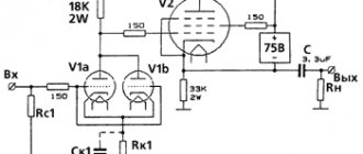
Push-pull ULF circuit
As a result of experiments and small changes, I came up with this diagram.
Looking ahead a little, I will say that the amplifier develops an output power of 10 W at an input voltage of 0.5 V. The circuit itself, in my opinion, is quite interesting and non-trivial. It combines the advantages of single-stroke and two-stroke. From the first she inherited the input stage, which, strictly speaking, has no special features (except, of course, for the method of powering the second pentode grid). From the second is the output stage (operating, by the way, in class A), and here there are continuous features.
The first is the connection of the control grids of the output lamps, it is direct. That is why there is a relatively high resistance resistor in the cathodes of these lamps (to maintain the mode of the output lamps). But such circuit design entails the main disadvantage of the circuit - its large heat generation. Therefore, initially it is necessary to provide sufficient ventilation of the housing.
The second is to supply the input signal only to the grid of the upper arm (the grid of the lower tetrode is grounded by alternating voltage). This method is called Self-Inverting Push-Pull (SIPP), or self-splitter - a self-inverting push-pull output stage. Its characteristic feature is the absence of capacitance in the cathodes of the output lamps. Since the inverse input signal is supplied to the lower tetrode precisely through its cathode.
The third also applies to the first stage - feedback from the cathodes of the output stage to the screen grid of the input stage, increasing the overall stability of the amplifier.
As you can see, both cascades are connected to each other by constant voltage, and in a circular manner. This entails a rather painstaking setup of the amplifier, which consists of carefully selecting resistors R3, R10 and R11. But for all these difficulties and difficulties I was rewarded with a wonderful sounding amplifier.
↑ Weekend trances - 80% of the success of any lamp player
I wound the output trances on PL hardware from the TS-90. You need to choose iron based on the following calculation: Sound power = 1/5 of the Overall power. Their maximum output power is about 15 watts. Suits us! Winding data
I - 4000 volts with 0.23 mm wire II - 80 vit with 0.9 mm wire for a load of 4 Ohms + 30 vits for 8 Ohms.
A very convenient thing is taps for different loads if you have several pairs of acoustics. The lower limit of playback was calculated at 15 Hz. Primary and secondary in series.
Here is the winding diagram for 1 coil. And a diagram for connecting the windings of 2 coils.
Fragment excluded. The full version is available to patrons and full members of the community.
ULF assembly
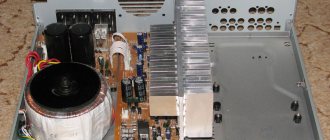
Now assembly. One side panel from an old computer case was used for the chassis, and the second one was used for the bottom. According to the intended design, the lamp panels should be raised above the chassis, so rectangular holes were cut out in the latter, which I covered with foil fiberglass boards with lamp panels soldered into them.
There was also this remark in the original source.
Therefore, it was necessary to come up with an anode voltage delay. I didn’t want to put the toggle switch on the anode, because I don’t like sharp transient processes in the form of surges in the anode and grid currents. Taking into account the above (and shown), the power supply and softstart circuit turned out like this.
Power supply and softstart diagram
What happens? After turning on the amplifier, the filaments heat up for the first 30 seconds, then the anode voltage gradually increases for about 45 seconds, and then the signal level indicator on the front panel turns on, signaling that the amplifier is ready for operation. Both relays remain in the released state after all manipulations. By the way, about the indicator. His scheme is like this.
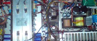
The design of the indicator has been described here. Two more points that are not on the diagrams. The first is a selector for two inputs, which are switched by two small-sized RES60 relays, one relay for the right channel, the other for the left. In principle, it would be possible to get by with just one, but then, during the warm-up of the amplifier, one of the inputs would be connected to the signal source, and I did not like this. The second point is the headphone output, which is organized in exactly the same way as in the link. I used a TS-200 transformer from a tube TV as a power transformer. But this is due to its poverty, since coping with its main drawback - buzzing - is very difficult. Here is a photo of installing and starting up the amplifier.
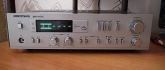
Next, through simple manipulations with bamboo-style cutting boards, as well as wooden blocks and planks, I refined the appearance.
The back wall was made of PCB 4 mm thick and painted gray. I painted the chassis the same color, and glued two plastic covers to the front, cut from the bottom of an old, disassembled scanner.
When I drilled holes for the lamps in the panel board, I made a mistake with marking them. The lamps were not in the center of these holes, so I had to cover this mess with rings. Our turner sweated while making them. Well, nothing, but it turned out even more beautiful.
At the same time I forced him to grind out the knob for the volume control.
I planned to cover the power supply compartment with a mirror, and the indicator with tinted glass. A mirror maker I know helped me with this by cutting scrap panels to size.
Then I couldn’t resist and made LED lighting for the mirror. Here's a view from below and from behind.
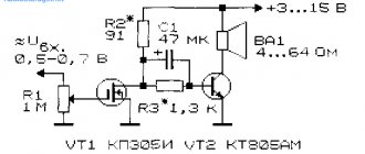
↑ Smooth supply of anode
A smooth supply of anode voltage is also needed.
Otherwise, when starting to charge the containers, the power supply will operate at low resistance and will go into protection. Fragment excluded. The full version is available to patrons and full members of the community.
Only ultrafasts are suitable for the diode bridge. Slower ones will get very hot. Capacitors C1 and C2 regulate the delay time. With 10 µF the output to operating mode is about 3 minutes. Any field switch with a suitable voltage will do. It will need to be hung on a small radiator, because at the moment of opening the field will heat up. Well, it is advisable to hang something in the anode load, otherwise the output voltage will differ more. I hang two 220V x 40W lamps connected in series as a load.
Photo of the finished device. This board is for a different amplifier, differs only in the presence of a bias winding.
Amplifier Specifications
That, in fact, is all about the scheme and design. It remains to talk about the performance characteristics of the amplifier. As I already said, it works in class A and with 8 watts of output power it has the following parameters:
When the output power increases to 10 W, the nonlinear distortion factor increases to almost 1.2%. Amplitude-frequency response:
What does this circuit demonstrate that is so special about sound? First of all, it is more similar to a single stroke than a two stroke.
Listening to him, I involuntarily feel like I’m sitting by the fireplace, almost in a rocking chair. In addition, the inherent clarity and detail of a push-pull amplifier is retained. Well, and power, of course. And the bass is so clear and lively that you want to touch it with your hands. I think this is primarily due to the absence of coupling capacitors.
If I had also had the opportunity to wind the output transformers myself, I don’t know what I would have heard then. I hope I will have such an opportunity, so there is still more to come! Especially for elwo.ru – Gamzan.
Tube Forum
- TUBE ULF ON 6F3P (6BM8, 6PL12, ECL82)
- TUBE FOR HOME AUDIO SYSTEM
- TUBE ULF FOR 6P14P AND 6N2P
- TRIODE AMPLIFIER
↑ Housing
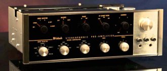
For me, the body is simply incredible work. I can apply extraordinary patience and still it will turn out crooked and miserable. And in general, when it’s collected, it lies on the floor, works and sings - it opens up a terrible attack of laziness to do anything further.
I'm putting everything in its place. I wanted to make an illustration, but as always I was deceived with the sizes.
Covered with sheet plastic.
Air outlet at the top.
And finally assembled: