Electret microphones are widely used in modern household and special equipment. They are distinguished by their compact size and high quality sound signal transmission. The main disadvantage of the design is the very weak output signal and the mandatory supply of polarizing voltage to the capsule. A preamplifier for a microphone can be made using any element base. Homemade designs use both transistors and integrated circuits. Device circuits differ in the number of stages, the presence of automatic gain control and other technical solutions.
Amplifier for electret microphone
A microphone amplifier for a microphone is used to amplify weak signals of 0.1-15 mV to a level of 200-400 mV. The microphone preamplifier circuit is simple and includes one or two amplification stages and, if necessary, micro frequency response correction circuits. The main design parameters are the following values:
- frequency range
- Harmonic distortion factor
- Signal to noise ratio
- Gain
A good amplifier for micro should provide a frequency range from 20 Hz to 20 kHz with frequency response unevenness no more than ±1.5 dB. The necessary frequency correction is carried out in further low-frequency stages. The harmonic coefficient in the entire frequency range should not exceed 0.2%. Since the microphone device is the first stage, all internal noise will be amplified by the low-frequency path. Therefore, microphone amplifier circuits use the lowest noise transistors and integrated operational amplifiers.
↑ Payment
This amplifier was also tested for Skype. Instead of a button, you can use a switch; a transistor and resistors R5-R7 are not needed, neither is C2. The gain is enough to not include additional +20 dB microphone gain in the sound card mixer. This has a positive effect on sound quality and ease of use. Of course, you need to set the volume and sensitivity to a reasonable level to avoid acoustic feedback.
Microphone amplifier for electret microphone
An electret micro with a loud sound produces an output of about 10-15 mV, so to amplify the signal to a level of 400-600 mV, a circuit with one or two stages can be used. The design can be assembled using a conventional or field-effect transistor and an integrated circuit. The microphone amplifier on one transistor is made on a low-noise device with reverse conductivity. The circuit is suitable for use in the audio paths of personal computers. The advantage of the device is its low-voltage power supply and can be powered from a 1.5-volt AA battery. The size of capacitor C3 can be changed within the specified limits.
Problem
Most cheap microphones don't have a default sensitivity enough to be heard clearly. You have to scream, but you can’t do that on a regular basis; yelling is a tiresome and harmful activity.
Having carefully studied the issue, I came to the conclusion that the manufacturers are to blame for the situation, overly simplifying the design of the device. Having given his hard-earned 100-500 rubles, the buyer essentially receives a module (capsule) of an electret microphone without any electronic “piping”.
Electret microphone and standard 3.5 mm jack. This design does not allow the microphone to be sensitive, but you can record sound
All sorts of flexible legs and clothespins are optional tinsel. Formally, such microphones work, but their sensitivity and recording quality are low (noise is heard). There's nothing stopping you from adding a few electronic components to the circuit to improve the microphone's ability to pick up quiet sounds.
A typical representative of electret microphones
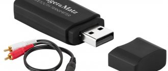
I'm also not considering purchasing a separate sound card. This was already in the article “How to set up a microphone, record and process sound - instructions for beginners.”
Dynamic microphones already have a built-in amplifier
Amplifier circuits are quite simple, so people who know how to use a soldering iron remake microphones and enjoy life.
Electronics engineers are successfully refining microphones (source)
By the way, even cheap buttonholes for 100 rubles include good electret modules. For example, I have a Genius clip-on microphone from ten years ago, it works great. After modifications, of course.
In addition to low sensitivity, you can hear a low hiss on the recordings. It can be suppressed by filters in an audio editor, but when the interference is too strong, removing noise will distort the useful part of the recording and the voice will sound dull, as if from a barrel.
Read also: How to lubricate a Makita hammer drill
Noise (in 99% of cases this is interference from electromagnetic fields) appears at several stages of sound delivery:
- In the electret capsule of the microphone.
- In the microphone preamp, if available.
- When transmitting a signal via a connecting cable that is not shielded from interference.
- In the sound card amplifier.
The most painful place is the computer's sound card. Replacing with a better one and/or moving it outside the computer case can get rid of the noise, but not everyone has the money for such an upgrade.
Most often, the user is left alone with a cheap microphone plugged into a loud hissing sound card soldered to the computer motherboard. You can try to make the sound louder programmatically.
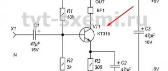
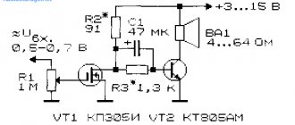
Microphone amplifier with one transistor
The field-effect transistor circuit has a low self-noise level and provides a gain of about 20 dB. To do this, it was necessary to increase the supply voltage to 9 V, so the amplifier is powered by a Krona battery or from an external power source. When repeating this circuit, you need to remember that field semiconductor devices are afraid of static electricity, so soldering the transistor must be done with a grounded soldering iron and use an antistatic wrist strap. Before soldering, the leads of the transistor must be connected to each other by wrapping them with thin copper wire. Transistor microphone circuits have various technical solutions. They come with several stages, with automatic gain control and noise reduction.
In the first case, through resistors R4 and R1, the supply voltage necessary for its operation is supplied to the electret microphone. An alternating frequency signal from an electrodynamic device is supplied through capacitor C3 to the base of the transistor. The amplifier for a dynamic microphone is assembled using a single reverse conduction transistor.
Transistor BC547 is replaced by KT3102E. A correctly assembled circuit starts working immediately and does not require adjustment. A microphone amplifier circuit using a single transistor cannot always provide the required parameters, so in practice circuits with a larger number of stages are often used.
An electrodynamic microphone is connected to the microphone amplifier, but the circuit can also be modified for an electret device. To do this, the electrolytic capacitor C2 is replaced with a regular one with a capacity of 4.7 μF, and the supply voltage is supplied to the point of its connection with the micro through a 2-3 kOhm resistor. The gain of the device reaches 200 in the frequency band from 40 Hz to 20 kHz. The use of transistors of different structures made it possible to eliminate the transition capacitor between stages. It usually introduces noticeable distortion into low frequency amplification circuits.
↑ Implementation
I used a housing from an electronic ballast for halogen lamps, cut a hinge from a Genius microphone and glued it into the housing. The power button is from the keyboard of a Panasonic desk phone (available in markets). Standard tact buttons either have a short stem and are awkward to press, or the stem is too long and cuts into your finger, so look for something that is comfortable for you to press. The buttons work normally even with dirty contacts with a resistance of tens of ohms.
I've built several LM386 amplifiers and they all worked right away without any adjustments. On one board, due to tinning of the tracks, the output of the microcircuit was short-circuited; when a signal was applied, the LED went out due to a drop in battery voltage, but the microcircuit did not burn out. The amplifier is quite versatile and can be used in many ways.
Obviously, there is no universal microphone amplifier. Singers need one thing, room listeners need another. There are also issues with food. Moving the microphone away from the mouth increases the proportion of reflected signals and changes the timbre, we must remember this and not be surprised. As for Skype, I came across the fact that in some cases the sensitivity of the microphone input is not enough, there really is a problem. My attempts to make an amplifier powered by the output of a computer's microphone amplifier were unsuccessful. It’s easier to make an autonomous power supply that can work for months, and the amplifier will work with any computer.
Microphone amplifier circuit on a chip
There are many microphone amplifier designs on a chip. Most often, devices use operational amplifiers, but there are integrated components that represent a ready-made microphone channel. An example of such a design is the specialized low-noise microphone amplifier microcircuit MAX9814. It has the following parameters:
- Programmable gain – 40, 50 and 60 dB
- Harmonic distortion – 0.04%
- Built-in power supply for electret micro – 2V
- Temperature range – +80- –400С
- Has automatic gain control
For independent repetition, circuits based on integrated op-amps are suitable.
The circuit is assembled on the domestic OU 157UD2. This is a microcircuit with a very low noise level that is not critical to the supply voltage.
The high-quality channel is designed to work with all types of electret microphones. It uses a BA4558 or JRS4558 op-amp. Capacitors C1 and C4 are 0.22 µF each. The circuit is highly sensitive. Does not require adjustment and starts working immediately after supply voltage is applied. The following device uses the K538UN3B microphone chip.
It is very simple, since it does not contain resistors and its assembly requires only a microcircuit and four capacitors. The supply voltage can be reduced to 3 volts without large gain losses. When repeating designs, you need to connect the microphone amplifier with a shielded wire and connect the screen to the device body.
↑ Scheme
Fragment excluded. The full version is available to patrons and full members of the community.
Resistor R4 is necessary; without it, excitation may occur, which manifests itself in a sharp increase in current consumption. To work with headphones, I reduced it to 100 Ohms, but I do not recommend shortening it. To increase the gain to 46 dB, you need to solder in capacitor C. Almost any capacitors can be installed; in the original source there were 10 μF and 0.1 μF.
I try to draw boards with the widest possible tracks so that they can be drawn even with a match. The LED and power button are located on the housing cover. I haven’t connected the amplifier to radio stations from other companies, but I think that their connectors and sensitivity are standard, especially since the gain can be adjusted. To prevent those on duty from doing this at their leisure, I made a hole in the housing cover for a thin screwdriver.
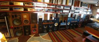
Amplifier with microphone input
Low-frequency designs designed to amplify audio frequency signals are always equipped with one or more microphone inputs. These are the most sensitive audio channel inputs. When operating external audio devices, you should avoid connecting devices with high output signal levels to the ULF microphone inputs. This may cause the input transistors or integrated circuits to fail. Professional devices are equipped with XLR connectors that allow you to supply phantom power to condenser microphones.
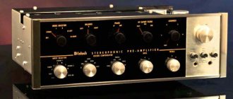
↑ Input transformer
In general, what should the input transformer of a microphone preamp be like:
- A certain transformation ratio (preferably from 1:7 to 1:16)
- Permalloy core (best frequency response)
- Armor made of steel or better permalloy
- Determined DC resistance of the primary winding
If in general everything is clear with the first 3 points, then what about 4?
Any specific one? But here opinions differ, and in some places radically. Someone claims that the resistance should be equal to the DC resistance of the source. In my case it was about 250 Ohms, so I selected a transformer with exactly this resistance. However, there is an opinion that transformers with a resistance an order of magnitude lower than that of the source are very suitable. Exactly as there is an opinion that it would be better to have an order of magnitude more. Well, I didn’t have a transformer an order of magnitude smaller, but I tried an order of magnitude larger and, frankly speaking, did not find any difference (by ear). We also need to mention the transformation ratio. Why exactly like this? Why not less?
Firstly
, the main reason is that the lamp has a very high input impedance. And if you directly connect a microphone to it, you will get the same thing as when connecting it to a laptop - some of the frequencies will simply be absorbed. And this comes with the added bonus of tips. That is why a transformer is needed that can coordinate one with the other. How exactly? Very simple! The resistance scaling factor is equal to the square of the transformation ratio. In other words, if I have a transformer with a transformation ratio of 1:7 and I connect a microphone with a resistance of 250 ohms to it, then for the lamp it will be as if I connected a source with a resistance of 250 * (7 × 7) = 12250 ohms to it! This is an excellent indicator; such resistance for a lamp will be very appropriate.
Secondly
- noise. Modern transistor preamps make quite little noise. This is, of course, due to more advanced technology and design features. More precisely, the absence of thermal noise. Why should it get so hot there? And the lamps, needless to say, are just a real heater! Only the temperature of the 6N2P lamp cylinder can reach 90 degrees, what is going on there on the filament? Of course, there is decent thermal noise there. Especially if the source is as weak as a microphone. Then, to bring the signal level to normal, you have to greatly increase the gain, due to which the level of this same noise also increases. But a device with a lot of noise cannot reach a level that is any good. And here is a simple option - put a transformer at the input and increase the signal (in my case) 7 times! This means that the lamp gain can be reduced by 7 times, and the noise will be reduced by exactly the same amount. Simple and tasteful. But why then did I indicate that the transformation ratio is needed up to 1:16? Is it even possible to increase the signal with a transformer all the way, and install the lamp as a buffer? No, it won’t work like that, the transformer’s own distortions will come into play, which will worsen the characteristics of the preamp.
And thirdly
, the transformer at the input gives what neither transistors nor lamps can provide - a full-fledged balanced input with galvanic isolation. Those who have received electric shocks from a microphone to their lips at rehearsals or concerts will understand me perfectly.
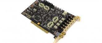
We’ve sorted out the type of transformer, now let’s go online to look for them. It’s amazing, but they have a price tag of 1500 rubles! Wait, look in the wrong place. Yes, there are professional transformers, but we don’t need that now! Therefore, we go to the collapse or flea market. What to look for: old industrial modems of low speeds (up to 56 kbits per second), old radio relay systems, old devices for RS-232 or RS-485, other old digital crap. I came across a very interesting unit from a radio relay system. It was there that I found these wonderful transformers:
I must say that I was slightly surprised by the large size of the transformer and low weight. And, of course, I bent the casing fasteners to see what was inside. Inside there was a small transformer waiting for me, quite small. Something like transformers in microphones and... ordinary computer modems for telephone lines!
Yes, with the exception of the lack of armor, transformers from some modems are ready for use in a preamp, because everything is as ordered - a permalloy core, a transformation ratio of approximately 1: 7.5, a primary winding resistance of about 300 Ohms. But there are also exceptions. However, all you need is a winding machine or patience.
How to programmatically enhance sound
It may turn out that the sound card installed in your computer is good. Then turning on the microphone boost will help.
Right click on the speaker icon
Right-click on the connected microphone - Properties
In the properties, find the “Levels” tab, there will be sound amplification settings.
Microphone gain on the Levels tab. Don't forget to click OK
Depending on the sound card driver, there may be a “Mic boost” option instead of sliders or nothing at all.
Unfortunately, with useful sound comes increased noise.
If you don't put the microphone in your mouth and don't turn on the gain, a quiet recording in an audio editor looks like this:
Those who have worked in Audacity will immediately understand: the recording is not loud enough. We turn on the gain and... alas, the noise will increase along with the voice:
This is acceptable for communication via Skype. And if you can turn on the noise reduction filter in the driver, life is good. Even if the voice sounds like it’s coming from a barrel, you can understand the words and that’s okay.
But to record podcasts, video lessons, and especially vocals, you need a good sound source. No one wants to listen to a constant “shhh” in the background of even the nicest voice in the world.
Remember!
Increasing the sensitivity of the microphone does not always contribute to high-quality recording: the better you hear the surrounding sounds, the stronger they will sound in the recording. And if you're recording a podcast in a room with a chirping parrot, a lot of signal amplification will only get in the way. You need to find a balance between sensitivity, interference noise and background sounds so that during processing you can get rid of unnecessary elements.
How to connect a microphone correctly
To achieve high-quality sound, you need to know how to connect a microphone to a computer. Not everyone understands what kind of multi-colored inputs are located on the back panel of a desktop computer. It’s easier with laptops: there are always explanatory icons near the connectors; on desktop PCs this is a luxury.
(There may be connectors for connecting additional speakers, which is great for creating a home theater; we don’t need them.)
There are three main connectors: speaker output (headphones), microphone and line inputs, each assigned a specific color.
Why you need a microphone input and speaker/headphone output is clear from the name. And with linear (Line in) the situation is more interesting. It is also designed for recording sound, but is simpler.
| Microphone input | Line input |
| The voltage supplied is 2 - 5 Volts, the exact value depends on the sound card model | No output voltage |
| A preamplifier is installed, amplifying the signal approximately 30-50 times | No amplifier |
A device connected to the microphone jack is supplied with voltage (so-called “phantom power”), and the return signal passes through an amplifier. This is where the noise in the recording arises: firstly, the supplied power has its own frequency, and secondly, the electronic components of the sound card catch and make louder all the noise and signals from the microphone and surrounding devices.
The linear input does not have phantom power, and there is no amplifier as such. A powerful signal is needed, but when digitizing the signal, a minimum of extraneous noise is mixed in. For example, you can take an old cassette player and connect its headphone output to Line in - this way you can digitize audio cassettes.
Electret and condenser microphones cannot simply be plugged into a line input. More precisely, the electret will work, but without power it, being a very weak current generator, will produce a too quiet sound, almost inaudible.
What to do? Why know this nerd? And to the fact that there are two types of amplifiers that can increase the sound volume, connected either to the microphone or to the line inputs. And you need to understand which option is right for you.
- Built into the microphone, powered by voltage running along the microphone cable. They amplify the signal up to 10 times (I can’t say exactly in decibels), and are highly vulnerable to interference.
- With external power supply from batteries or a separate unit. They can amplify the signal 10-1000 times and connect to the linear input. The noise does not disappear anywhere, but relative to the useful signal it is a hundred times quieter, therefore, by connecting even a cheap hundred-ruble lavalier through an amplifier, you can get high-quality sound.
Read also: Rubber-coated rollers for machine tools
That is, ideally, the microphone should be connected through an amplifier to the line input and everything will be OK.
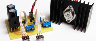
↑ About nutrition
Make the power supply as you like, install stabilizers, electronic filters and delays in the supply of anode voltage. Soldering iron in your hands! Everything was simpler for me. In the photo above you can see a large and scary toroidal transformer, giving 6.3 and 12 volts at the output, a power supply board that rectifies 12 volts and, with the help of a “flip” transformer, makes 220 from 6.3, which are then rectified and turned into the 300-volts we need. 310 Volts constant. I needed 12 Volts to power the output buffer (on the back of the case), which I had to add to perform very specific tasks. Usually it is completely unnecessary.
↑ About other details
Now let's return to our diagram. It is characterized by simplicity. Only the following details deserve special mention: C3 and C4 are capacitors that suppress excitation or ringing. It is recommended (if possible, of course) not to install them. But alas, this opportunity does not happen often. It’s impossible to say for sure what exactly influences the appearance of excitation, whether it’s the wiring, or the lamp, or the housing... But one thing is for sure - excitation gives the sound a disgusting shade. You can only see it on a good oscilloscope, so if you have doubts, it is better to raise them. R6 is a resistor that sets the gain. Instead (just to the drawn contacts), you can connect a regular variable resistor with a resistance of 15-20 kOhm, thus organizing a “Gain” regulator. That's exactly what I did. Nothing more. Isn't it very simple?