Gain classes are a completely logical and understandable way to distinguish one typical circuit from another. However, when applied to tube circuitry, this approach turned out to be insufficient. Depending on the type, the lamps are capable of operating in different modes, which are equally applicable in amplifiers of different classes. This fact multiplies the number of possible combinations, not to mention the fact that the operating modes of the lamps can be modified, combined and combined. Of course, we won’t dive so deeply into circuitry, but we will try to understand the basic concepts.
Story
Tubes, like other electronic components, have a rich history that has seen significant evolution. It all started in the 2000s of the last century, and the end of the tube era can be considered the sixties, when the last fundamental development saw the light of day - miniature radio tubes, Nuvistors, and transistors had already begun to actively conquer the market. But from the whole history we are interested only in the key stages when the main types of radio tubes were created and the basic circuits for their inclusion were developed.
The world's first triode by inventor Lee de Forest, 1908
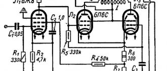
The first type of radio tubes developed to create amplifiers were triodes. The number 3 is heard in the name for a reason - this is exactly how many active outputs the triode has. The operating principle of a triode is extremely simple. Between the anode and cathode of the lamp, the power source and the primary winding of the output transformer (to the secondary winding of which the acoustics are connected) are connected in series. The useful signal is supplied to the lamp grid. When voltage is applied to the amplifier circuit, a flow of electrons flows between the cathode and anode, and the grid located between them modulates this flow according to changes in the level of the incoming signal.
As triodes were used in various industries, it was necessary to improve their characteristics. One of these characteristics was the pass-through capacitance, the value of which limited the maximum operating frequency of the lamp. In the process of solving this problem, tetrodes appeared - radio tubes with not three, but four electrodes inside. The fourth was a screening grid installed between the control grid and the anode. This solved the problem of increasing the operating frequency to the fullest extent, which completely satisfied the creators of the technology, who developed tetrodes so that radio stations and radio receivers could operate in the short-wave range, which has higher carrier frequencies than the medium- and long-wave ones.
Triode structure
From the point of view of sound reproduction quality, the tetrode did not fundamentally surpass the triode, so another group of scientists, puzzled by the issues of reproduction of sound frequencies, improved the tetrode, using essentially the same approach - simply adding another additional grid to the lamp design, located between the shielding grid and anode. This was necessary in order to suppress the dynatron effect - the reverse emission of electrons from the anode to the shielding grid. Connecting an additional grid to the cathode prevented this process, making the lamp's output characteristic more linear and increasing power output. Thus a new type of lamp appeared: the pentode.
↑ Design and installation
Construction, design - here whoever can do it. I ordered the cutting of elements from laminated MDF at the Design Furniture store; this is, of course, not an array of expensive wood, but for us, “beginning high-end specialists,” it is quite suitable.
Speaker terminals on the rear panel.
On the front panel there are volume controls, input “tulips” and pointer devices for monitoring quiescent currents. The potentiometer for setting the quiescent current on the ultrasonic circuit board should be easily accessible. On indicator - lamp glow. Ultrasound board (chassis) – non-foil fiberglass 5 mm. Non-foil to reduce installation capacity, everything “hangs in the air” (as on the breadboard) and the design “breathes easily”.
Conductors: single-core, copper, tinned or even silver-plated installation wire (wire). AC circuits: twisted pairs of flexible stranded wires. Mounting on lamp panel contacts, electrolytic capacitor terminals and stands installed “in situ” during the assembly process.
The transformer casing is glued together from plastic and painted with matte enamel from a spray can.
Principle of operation
All of the above types of lamps have found application in audio technology in one form or another. At the same time, the inquisitive minds of audio engineers were constantly looking for ways to use them most effectively. Quite quickly they came to the conclusion that the place where the pentode shielding grid is included in the amplifier circuit is a tool with which you can fundamentally change its operating mode. When the grid is connected to the cathode, we have a classic pentode mode, but if we switch the grid to the anode, the pentode begins to operate in triode mode. This allows you to combine two types of amplifier in one with the ability to change modes using a simple switch.
This is how a tetrode works
But the matter did not stop there. In 1951, American engineers David Hafler and Harbert Keros proposed connecting the pentode grid in a completely different way: to intermediate taps of the primary winding of the output transformer. This connection is something between a pure triode and a pure pentode connection, making it possible to combine the properties of both modes.
Thus, the same story happened with the lamp modes as with the amplification classes, when, after the “pure” classes A and B, a combined class AB appeared, combining the strengths of the previous two.
Designation of different types of lamps according to GOST
With regard to the combination of lamp operating modes and amplification classes, they can be combined in an arbitrary manner, which leads to a fair amount of confusion and even heated debate among neophytes. It does not add clarity to the fact that developers of tube amplifiers in most cases indicate not the amplifier class, but the principle of circuit design: single-ended - SE (Single Ended) or push-pull - PP (Push-Pull). As a result, pentodes and tetrodes are often associated exclusively with class AB and a push-pull circuit in general, while a triode, on the contrary, is considered synonymous with class A and purely single-ended switching. In fact, nothing prevents you from switching an amplifier operating in class A to a pentode or ultralinear mode, and using a pair of triodes you can assemble a push-pull amplifier operating in class B or AB.
A prerequisite for incorrect associations is the frequency of use of certain modes in different amplification classes. Triodes are more often used in single-ended circuits and class A. In turn, pentodes and tetrodes are better suited for operation in push-pull circuits, although switching them to triode mode is a real option found on amplifiers operating in class AB, and has absolutely no relation to class A.
↑ Acoustic systems
There are many examples of acoustic design for loudspeakers, how to choose the best?
We need high sound pressure output over a wide range at low “tube” powers. We will proceed from the availability of acquisition and manufacture of components, ease of implementation of the design and decent appearance. After comparing different options, assessing the positive and negative aspects of this or that design (“Labyrinth”, “Speaker”, “ORTO”, “TQWN”, etc.) and despite a lot of contradictions, I settled on “exotic”: “reverse, broken-exponential horn." It is somewhat cumbersome, but it is not possible to implement the horn principle (exponential expansion of the “pipe” cross-section) otherwise. I also post the drawing “working, charged.”
Fragment excluded. The full version is available to patrons and full members of the community.
The length of the “reverse horn” (from the speaker cone to the port) is about 2.2 meters (if we consider it as a quarter-wave labyrinth, then the resonance frequency = 40 Hz). The expansion of the horn cross-section (broken-exponential) gives an increase in output at low frequencies. The initial cross-section of the horn is slightly smaller than the effective (radiating) area of the rear side of the speaker cone, which gives a slight “compression” in the pre-horn chamber, increasing the damping of the system in the region of the main resonance.
Selecting dynamic heads.
Low-frequency link - 6GD-2RRZ, 10-inch domestic “woofers”, vintage and rarity, but you can still buy them. HF link - here I changed my ideology regarding silk “domes”, because the price of real silk does not fit into the budget of a “beginner”. We will use automotive HF heads “TEAC TE-T100”: a cast duralumin horn and a titanium membrane.
There are no complex filters, the HF head is connected through a 1 µF capacitor K73-16 and a 3.9 Ohm 5 W resistor in series to match the sensitivity of the 8 ohm woofer. To protect the woofer cone, I purchased 10-inch “grills” that are attached to the speaker flanges using double-sided automotive tape.
Peculiarities
From the point of view of the quality and character of the sound, each type of lamp and each switching mode has its own characteristics, so obvious to the ear that even the ultra-linear mode, in fact, did not become the golden mean. Pure triodes and triode inclusion of pentodes provide the clearest and most spacious sound until it comes to energetic music with fast and significant volume changes. In other words, triodes are much better suited for calm jazz than for listening to rock.
Pentode and ultralinear modes, on the contrary, are more suitable for energetic music, but in some cases they do not sound clean, accurate and detailed enough. These complaints especially often relate to the pentode mode, and in general the sound character of both the pentode and ultralinear modes is often compared to transistor amplifiers.
↑ Results
This is the kind of “vegetable garden”, or rather “high end” we have created.
Personally, I didn’t come up with anything new here, I chose the best and simplest, optimized it, and this is the result. “Perfection is achieved not when there is nothing to add, but when there is nothing to take away.” S. Exupery.
With regard to this design: there is nothing to improve, except, perhaps, one thing: you can increase the supply voltage to 370 - 420 Volts in the shoulder. It will be necessary to use another anode-filament transformer and accordingly increase the values of resistors R4, R7 to maintain the driver lamp mode.
Practice
Tube circuit design is a delicate matter, so most manufacturers practice improving one particular combination of tube operating mode and amplification class. The desire of developers to obtain an ideal (according to their ideas) sound and the subsequent rejection of any alternative methods of switching on lamps is quite understandable, but when searching for a test subject, our task was exactly the opposite: to be able to compare the same set of lamps in at least two versions inclusions.
This significantly reduced the choice of candidates, however, a suitable option was found. It was the Cayin CS-100A - a device literally created for all kinds of experiments. Its design allows the use of two types of output tubes: KT88 tetrodes and EL34 pentodes. It is possible to choose between triode and ultra-linear modes with an output power of 50 or 80 W per channel, respectively. Moreover, the amplifier circuitry in both cases is push-pull, and it operates in class AB.
Among other things, the Cayin CS-100A is a good example of a modern implementation of a traditional tube amplifier. It has a classic layout with a removable cover lamp grille, and carries on board output transformers of substantial size, providing not only sufficient power, but also a wide range of reproduced frequencies. The components meet modern quality requirements: the amplifier uses carbon resistors, audiophile capacitors, a toroidal power transformer and silver cable wiring. The installation was carried out using a hinged method - just as it was done more than half a century ago. This is not so much a tribute to history as a way of shortening signal paths. In general, the Cayin CS-100A is a device that fully fits the definition of a High End tube device.
↑ Settings
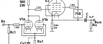
If the ratings are met, the lamps are in good working order and the output lamps are matched in pairs, there is practically nothing to adjust. Without L3 (L4), R5-R6 in the position of greatest resistance. We take turns checking the currents of the driver lamps = 1.5 mA (±0.1 mA), if necessary, select the values of the cathode resistors (R14, R15). We install L3 (L4) in place, using the milliammeter with the “operational” resistor R5-R6 we set the current of the output lamps to 50-70 mA. Resistors R16 are selected in advance, before installation, for the total deflection current of the indicator head = 100 mA.
Sound
When it comes to high-end components, especially tube ones, it is not always possible to clearly draw the line between “the amplifier failed” and “it was intended to be so.” After all, an audio engineer in the high-end world is also something of an artist and has the right to his own idea of how a system should sound. The use of two pairs of acoustic systems with fundamentally different characteristics during testing helped to avoid this kind of misunderstanding. Specific signs of a lack of power and an increase in distortion could be noticed under heavy loads and at above-average volumes, which generally corresponds to the stated characteristics. The Cayin CS-100A can handle large bookshelf or medium-sized floorstanders with the same average power, impedance and sensitivity parameters.
In triode mode, the amplifier produces a beautiful, timbre-rich sound with rich upper and mid-bass. Calm slow music, vocals, audiophile jazz, and chamber classics of small compositions sounded best. It was quite possible to enjoy the early Beatles and Led Zeppelin. At the same time, attempts to listen to modern rock and metal were unsuccessful. The sound of the guitars was very thick, viscous, round and not particularly aggressive. The most feisty metal was presented as if it had been recorded in the early seventies.
Switching to the ultra-linear mode is done with one click of a button and changes the picture completely: rock, metal, dance electronics shed their vintage touch and begin to sound no less energetic than on transistor amplifiers operating in class AB. There remains some warmth and a pleasant roundness to the bass notes in the character, but in very moderate quantities. On slow music and small compositions, the ultralinear mode is not as beautiful and expressive as the triode mode; the music is presented more calmly and smoothly.
↑ Cuts and materials AC
The cut was ordered from a furniture showroom.
The front panel is made of laminated MDF 16 mm, everything else is chipboard 16 mm. Fragment excluded. The full version is available to patrons and full members of the community.
The rigidity of the structure is very high due to the small width of the “front” and numerous partitions inside. Everything is screwed together with Euro furniture screws and sealed with silicone sealant.
I refused to dampen the internal surfaces and fill the “pocket” of the pre-horn chamber with a sound absorber, so as not to convert the energy of the sound wave into heat and not make the sound “cotton.”
↑ And now an unexpected bonus that grew out of our successful universal concept
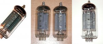
For the 6N9C
(Uc1 = -3.5 V, Ia = 0.75+0.75 = 1.5 mA) I made adapters from lamp panels and sockets + two resistors.
Installed instead of 6Zh8
. I listened, the result was as expected: it sounds!
Instead of
6Zh8
I tried
6Zh4
(direct “plug”), the difference is almost not noticeable, but it requires selecting lamps based on the maximum (and identical) anode current.
Alexander ( aleks8845
) gave me an idea and two high-inductance chokes for the so-called.
"nano-torics". I wound up the “primaries” from above for Ktr = 10, broke two unnecessary lamps, built “nano-lamp transformers” on the bases, added two resistors, two capacitors, two RCA connectors and got two more configurations for sources with their own volume control: audio PC card, player with output to phones, PC + DAC. This thing is installed instead of 6G2
. We get the shortest path: step-up transformer + output tube.
The result of listening from the DAC exceeded all expectations! The sound is dynamic, high detail and transparency, no “coloring”. Rock, “contraindicated” for single-ended amplifiers, sounded convincing and full. It is not clear where the pressure came from (clipping occurs at 5 Watts of power).
Instead of EL-34
KT-88 and 6P3S lamps
were tested , the result was positive.
I won’t say that the sound of these lamps with an order of magnitude difference in price is radically different. On KT-88
with a “nano-lamp transformer” we get only 1.5-2 Watts of sound, but what!
A total of EIGHT+ lamp switching configurations in one design!
Thank you for your attention! Thanks to Igor (Datagor) for his help in publishing the article.
↑ Nutrition
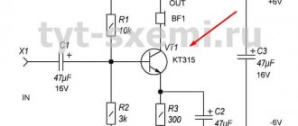
The anodes of the lamps are powered by an electronic choke using a field-effect transistor IRF830. I explained this scheme in my previous articles. The filaments of 6N2P and 6P14P lamps are powered from direct current through an adjustable stabilizer LD1084V with a load capacity of up to 5 A.
I have experimentally found that a 1K resistor (R20) is needed in the adjustment circuit in order to achieve an output voltage of 6.3 V under load (6.5 V at idle). At least 7 V AC must be supplied to the input of the diode bridge; for this I connected windings 11-12 and 15-16 in series.
↑ Two body layouts
It came to the hull. The customer had a torn Melodiya-103 stereo vinyl player that could not be repaired, and with a cockroach that had died inside. It was then that the idea came to me to use its body as a basis. I drew a layout of the elements inside the case.
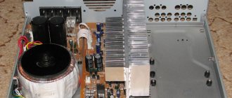
In the rear part there are two power transformers TN-56 and TA-199, shielded from the outputs and the main board.
Opposite them are all the hanging elements associated with the mains power - the power and fuse sockets, the switch. The preamplifier and preamplifier power supply boards are mounted on the left side. The input is located on the front panel. Showed it to the customer. — No, no, I need all the switching at the back, both the outputs and the input. Otherwise everything is fine. “But this is fraught with problems in the form of leads.” - Well, is it possible to do something about this? — It can be shielded, but these are additional problems.
The new and final layout of the elements looked like this.
The outputs are located on the rear panel above the input.
I started to implement the housing layout. I took the empty case from Melodiya-103 from the customer, disassembled it into parts, and threw away the excess. I sawed off the back and front panels to the customer's dimensions. Put it together, it turned out to be a rectangle consisting only of the back, front panels and side walls. The bottom cover of the original “Melody-103” is made of chipboard and is full of technological holes, this does not suit me and it goes to the trash. I decided to make the new bottom cover from laminate, it is much stronger.
For shielding purposes, I glued the bottom with metallized tape, having previously coated it with superglue for reliability. For strength, I tied the side walls together with three fastening sheets, onto which I installed 4 pins for fastening the main board. I drilled holes for the hanging elements and sanded everything down with primer sandpaper.
Primed.
The first primer showed all the surface imperfections that had not been eliminated.
I had to more carefully sand the surface and sand it with a sanding cloth. I primed it a second time. Everything turned out well. In place of the supposed entrance on the rear panel, a tinned piece of PCB was soldered onto which the screen will be sealed.
I also decided to make the input socket screen from PCB. I cut the blanks, tinned them on the inside and soldered everything together.
I drilled a hole for the wire and tinned the back wall. It was supposed to use a shielded wire, and the screen was tightly soldered around the outlet hole. I painted the body with matte black paint and installed power transformers.
I screwed on the top cover fasteners. They were made from furniture corners, onto which a washer and a nut with a diameter of 4 mm were sealed using soldering acid. For best symmetry above the hole, before soldering, secure the washer and nut to the angle using a bolt. You just have to be careful when soldering so as not to solder the bolt too. After the corner has cooled, the bolt is unscrewed.
I secured the preamplifier and preamplifier power supply to the case.
I covered the preamplifier board with a screen.
I installed a separating screen between the power transformers and the main board. I installed the board on the pins and secured all the missing fittings for the front and rear panels. Conducted installation of wires.
In this form I took it to the customer for a preliminary audition. - Everything sounds cool. - Exactly? - Exactly, finish the top cover and bring it back completely.
The top cover was made of metal. The power transformers are higher than the main body, so I thought about the threshold.
The piece of metal was not the first freshness, and it took some effort to remove all the rust from it. Afterwards I primed and painted. The holes for the sockets were initially drilled with a 16 mm drill and then drilled out with a dental drill to a diameter of 20 mm. I printed my label on photo paper, cut it out and glued it to the top cover with superglue.