Rebuilding VHF to FM units
Ten...twelve years ago, amateur radio magazines often published articles on converting imported receivers from the FM band (88...108 MHz) to the VHF-1 band (65.8...75.0 MHz). At that time, broadcasting was carried out exclusively in the VHF-1 range.
Now the situation has changed dramatically. The airwaves in the range of 100...108 MHz are almost everywhere filled. There are many imported and domestic radio receivers on sale with the VHF-2 range or with general ones (VHF-1 and VHF-2).
Since the VHF-1 range was virtually “orphaned,” a gigantic fleet of old radios and tape recorders remained “out of use.” They can be given a second life through a relatively simple modification of the VHF units of these receivers. The following points should be noted. Conversion of inexpensive portable receivers (“VEF”, “Sport”, “Sokol”, “Ocean”, etc.) should be minimal and ensure reception of 3...7 VHF-2 radio broadcasting stations in a given region. For stationary devices of a higher class with an external VHF antenna, it is desirable to preserve all its technical parameters (sensitivity, local oscillator stability, wide scale, etc.).
Typically, the VHF radio receiver unit contains an input circuit, 1-2 UHF stages, a local oscillator, a mixer, and IF stages. As a rule, these are 4 (less commonly 5) LC circuits. Having a basic (even better, wiring) diagram of the radio receiver, it is easy to determine all the necessary components (inductors, capacitors, etc.). The first circuit of the amplifier and all subsequent cascades do not need modification.
It is clear that for the range of 100...108 MHz, the capacitances and inductances of all LC circuits of the VHF-1 unit must be reduced. Theory and practice state that the capacitance of the circuit varies in proportion to the wavelength, and the number of turns of the inductor varies with the square root of this value.
When moving from the VHF-1 range to the VHF-2 range and with constant inductances (the number of turns of the inductors does not change) - this is an option for portable receivers for the mid-frequency ranges (69.0 MHz and 104.0 MHz) - we obtain the following ratio for capacities:
SUKB-2 = 0.44*SUKB-1.
where SUKV-1 is the total total capacity of the VHF-1 band circuit; SUKV-2 - the same capacity of the VHF-2 range. In a real circuit of VHF units, these capacitors include capacitors soldered into the circuit, parasitic mounting capacitances, interturn capacitance of the inductor, and input capacitance of transistors.
Taking this into account, in practice the following ratio of capacities is more suitable:
SUKB-2 = (0.3…0.35)*SUKB-1.
In addition, in VHF units it is possible to change the inductance of the loop coils within certain limits by rotating the tuning cores. Typically, the local oscillator of the VHF-2 block for the range of 100...108 MHz should be tuned within 110...119 MHz (with a margin) at IF = 10.7 MHz, and within 106...115 MHz at IF = 6.5 MHz, i.e. . higher than the signal frequency. On the schematic diagram of the UKV-1 unit, we mark those containers that will be completely soldered out of the circuit, as well as those containers that will be replaced with others with a lower rating. Typically these are miniature disk ceramic capacitors.
Capacitors must be selected in advance, cleaned and tinned leads, shortening them to a minimum. If there is no device for accurately measuring capacitance, the table below will partially help solve the problem. Table 1, where the size and color of the capacitor will indicate the limits of the nominal capacitance.
Table 1
| TKE group, body color | Limits of nominal capacitances (in pF) at case diameter | Marking dot color | ||
| 4mm | 5mm | 6mm | ||
| P120, blue | 1,0…2,2 | 2,7…3,9 | 4,7…7,5 | — |
| PZZ, gray | 1,0..3,9 | 4,7…7,5 | 8,2…10 | — |
| M47, blue | 1,0..4,7 | 5,1…10 | 11…15 | — |
| M75, blue | 1,0..11 | 12…24 | 27…39 | Red |
| H700, red | 10…18 | 20…33 | 36…56 | — |
| H1300, green | 18…47 | 51…82 | 91…130 | — |
| H70, orange | 680, 1000 | 1500 | 2200 | — |
For clarity, you can compare the capacitance ratings in the “VEF-221” and “VEF-222” radio receivers, which are built according to the same circuits with the same inductors (“VEF-221” has a range of 87.5...108 MHz, “VEF-221” 222" - 65.8...74.0 MHz). These data are taken from the factory instruction manual (Table 2). The capacitance ratings are given in picofarads.
table 2
| Receiver type | Capacitive input circuit divider | UHF Loop Series Capacitance | Parallel local oscillator circuit capacitance | Series capacitance of the local oscillator circuit | Capacitance in the AFC circuit | Parallel UHF Loop Capacitance | |
| C3 | C4 | C6 | C13 | C14 | C15 | C19 | |
| VEF-221 | 82 | 33 | 33 | 2/10 | 62 | 5,1 | — |
| VEF-222 | 33 | 82 | 47 | 22 | 75 | 12 | 15 |
The VEF-215 radio receiver and the VEF RMD-287S radio receiver have similar VHF block diagrams, so the data in Table 2 is also suitable for converting the VHF blocks of these devices.
Another example is a removable auto receiver of the “Ural-auto-2” type (input circuit, two UHF stages on GT322A transistors, a local oscillator on a 224-series microcircuit with the index ZHA1 or XA1). In the input circuit in the capacitive divider C1-C2 we change C1=22 pF by 5.1...6.8 pF, C2=33 pF by 10...12 pF. Capacitors C5, C7 and C14 are 33 pF each (series capacitances with the KPI of the 1st, 2nd stages of the UHF and local oscillator) are changed to 12... 13 pF. In the local oscillator circuit, we replace the tuning core made of ferrite (0 2.88 mm) with a brass threaded one (diameter 3 mm). Another example is the “Radiotechnika T-101-stereo” tuner (VHF unit on KT368A and KT339A transistors, tuned with KVS111A varicaps). Parallel capacitances SZ = 15 pF (input circuit), C14 = 15 pF (UHF), C18 = 9.1 pF (heterodyne) are dismantled. Series capacitances C4 = 130 pF, C13 = 130 pF (input circuit and UHF) are changed to 43...47 pF, and C15 = 82 pF (heterodyne) - to 27...33 pF. To stretch the scale, carefully unsolder the local oscillator coil and unwind 1.5 turns from the top of the coil and 1 turn from the bottom (the tap is from 0.9…1.2 turns as before). Then carefully solder the coil into place.
It is convenient to divide the process of altering VHF receiver units into several stages.
- We provide access to the VHF unit both from the parts side and from the side of the printed conductors by removing the covers of the receiver and the VHF unit.
- We determine the LC circuits of the input circuit, UHF, local oscillator, mixer, and the first circuit of the amplifier (the latter is not affected by the alteration).
- Carefully solder the containers that need to be replaced and dismantled.
- We solder new containers, prepared in advance (with cut and tinned leads) for each individual circuit of the VHF unit.
- Having made sure that there are no errors and the circuit is not broken (there are no bad solders, short circuits in printed circuits, etc.), we turn on the power to the receiver and try to hear at least one powerful (in a given location) VHF station. At the same time, we rotate the receiver tuning knob and the local oscillator core. It is very useful to have an industrial VHF-2 receiver nearby. This will help you immediately identify the desired station in the receiver you are tuning. Having heard at least barely a station, we achieve loud reception of this station using the trimming coil cores and trimming capacitors of the input circuit, UHF and mixer. At this stage, you can determine whether it is necessary to change cores from ferrite to brass and vice versa.
- By rotating the core of the local oscillator coil, we set the required location of this station on the receiver scale (focusing on an industrial receiver with the VHF-2 range). Typically, the section of the receiver's tunable scale, where stations in the 100...108 MHz range are located, occupies a very small part of the receiver's design scale (about one third).
- We pair the circuits of the input circuit, UHF and local oscillator of the tuned VHF unit. In the area near 100 MHz, we achieve the highest volume of stations by rotating the tuning cores of the input circuit, UHF and mixer, and in the area near 108 MHz - by rotating the rotors of the tuning capacitors of the same cascades (in this case, you need to monitor the position of the receiver tuning knobs - the maximum capacity of the KPI or varicaps at the beginning of the range and their minimum capacity at the end). We repeat this operation 2-3 times. In conclusion, it is necessary to reduce the capacitance in the AFC circuit by 2...2.2 times (if its nominal value exceeds 5...6 pF). The last stage must be carried out in the assembled VHF unit through the holes in the covers to adjust the capacitances and inductances with a dielectric screwdriver.
These general rules for altering VHF units should be followed for various schemes and designs of units. Briefly about receiving antennas. Obviously, directional antennas provide excellent reception quality, but they need to be rotated. For the rebuilt T-101-stereo tuner, the author uses a single square (two parallel copper wires with a diameter of 1.8 mm with a distance between them = 15 mm and a perimeter of slightly less than 3 m). The characteristic impedance of the square is about 110 Ohms, so it is powered by a PRPPM cable - 2 x 1.2 (the characteristic impedance is about 135 Ohms). The height of the mast on a five-story building is approximately 9 m. The plane of the square is perpendicular to the line Chisinau - Bendery - Tiraspol - Odessa. As a result, more than 10 stations in Chisinau and 3-4 powerful stations in Odessa can be heard.
Sources
- A short reference book for the REA designer (edited by R.G Varlamov). —M.: Sov. Radio, 1972, pp. 275,286.
- V.T. Polyakov “Direct conversion transceivers”. - M.: 1984, P.99.
- PM Tereshchuk et al. Amateur Radio Handbook, part 1. Kyiv: Tekhnika, 1971, S.Z0.
- "VEF-221", "VEF-222". Manual.
- Radiotechnika (tuner T-101-stereo). Manual.
- A.N. Maltisky, A.G. Podolsky. Broadcast reception in a car.— M.: Radio and Communications, 1982, P.72.
- V. Kolesnikov “Antenna for FM reception.” - Radiomir, 2001, N11, P.9.
VHF-FM receiver from an old TV
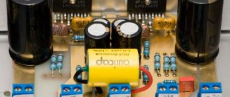
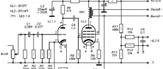
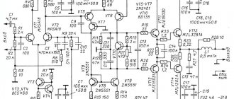
If you happen to have some blocks left over from old Soviet TVs of the 3-USTST , then you can use them to assemble a VHF-FM broadcast receiver with good parameters. Here is a description of such a receiver, which uses the USU-1-15 (module of fixed settings) and the MUNC module ( ULF module ) of the 3-USTST TV. The schematic diagram of the receiver is shown in Fig. 1 . VHF module diagram is shown in Fig. 2 . It is assembled according to a standard circuit diagram for the KS1066XA1 microcircuit.
USU-1-15 module differs from the MVP in that it is assembled on transistors and its eight-stable transistor trigger uses a voltage of + 31V not only to generate the tuning voltage, but also for its own operation. As the experiment shows, this trigger only works if the supply voltage is applied to it - the first is +12V, and the second should be at least 5-6 V more than the first. Only in this case will there be reliable switching of programs and retention of settings. Therefore, despite the fact that the varicap of the VHF module , assembled according to the standard KS1066XA1 USU supply voltage of 12V). And the level of the maximum output voltage setting is adjusted to the norm for the VHF module using resistors R1 and R2.
The power source is assembled on a Chinese TLG transformer, whose secondary winding consists of two 12V windings. It is possible to use another transformer suitable for the parameters. The entire winding is used to obtain stable voltages of +12V and + 21V. For stabilization, microcircuit A1 and zener diode VD2 are used.
The MUNCH module (A9.2 board) is also used ready-made. There is a wide variety of ULF for USCT televisions , assembled on both K174UN7 and K174UN14 . What unites them is the supply voltage and the numbering of the connectors for connection. In addition to the ULF , this module may include resistors for adjusting brightness, contrast and saturation, and also, in some cases, tones. As well as connectors for connecting a tape recorder and headphones, a varicap power supply stabilizer and others. In this circuit, only the ULF and its tone control (if any) are used. Since the TV uses an electronic volume control as part of the radio channel module, a simple regulator on the variable resistor R4 is used to adjust the volume in this circuit. The ULF is powered by an unstable voltage from the output of the tap of the secondary windings of the transformer. The supply voltage of the VHF module is reduced and stabilized by a parametric stabilizer on VD1. ready-made boards from 3-USTST as USU-1-15 and MUNC , then the VHF module is homemade. It can be assembled according to the diagram in Fig. 2 on a homemade printed circuit board ( Fig. 3 ). Board dimensions 45x40 mm. Or use a VHF module based on microcircuits like K174XA34 or K1066XA1 . Details . The KS520 zener diode can be replaced with other voltages of 18-22V, for example, KS522, KS518, KS218, KS220, KS222 , or dial from two or three. It is important that the voltage supplied to pin 26 of the USU-1-15 is at least 5V greater than the voltage at pin 24. Diodes - any rectifier, speaker also of any type.
author Poptsov G source: “RADIO CONSTRUCTOR”, 01 – 2005, pp. 12-13
Similar
Conclusion: which is better to buy?
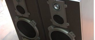
When choosing a radio, you need to consider where and what it will be used for. If you need a model for hunting, fishing, simple trips and travel, we can recommend taking the JBL Tuner 2 . This device is compact, and the moisture-resistant design will prevent it from deteriorating after being exposed to rain, which is especially important in the forest or mountains.
If a user is looking for a functional receiver that can also play music from SD cards and USB flash drives, we recommend considering the Ritmix RPR-102 .