Klimov D.A. Tube amplifiers. Calculation and design methods
The proposed publication belongs to the “Mass Radio Library” series and will tell the reader everything about tube amplifiers.
You will learn about methods for calculating, designing and creating amplifiers of this type, which serve for the highest quality of reproduced sound. In his book “Tube Amplifiers. Methods of calculation and design" Klimov D. A., the author places a significant emphasis on the practical side in the design of low-frequency tube amplifiers. Moreover, it should be noted that, despite the simplicity of the material presented, not a single nuance of the calculation and development of tube components of low-frequency amplifiers is missed in the presented book. A variety of options for constructing low-frequency amplifiers using tubes are considered, starting from input circuits and ending with output stages, matching transformers and power supplies. The book “Tube Amplifiers.
Methods of calculation and design" Klimov D. A. is divided into two sections, the first presents materials on the design and calculation of ULF on electronic tubes, the second section presents ready-made circuits and designs, a tube amplifier
power on triodes, bridge tube ULF, tube amplifier for headphones (headphones).
In addition to diagrams and calculations, the author of the book, Klimov, brings to readers information about the design features of tube ULFs, talking about how to properly assemble a low-frequency amplifier using tubes, about the technology of mounting tube circuits on a metal chassis, and provides drawings of scanners for the chassis and sheet metal housing. Readers are invited to prototype its components before directly assembling the ULF and a method is given for step-by-step debugging of low-frequency amplifier stages on a breadboard; this approach to the manufacture of a low-frequency amplifier will allow one to avoid errors that could cause the malfunction of a tube UMZCH. An interesting feature of this book is that it discusses the use of electromechanical feedback (EMF) in speaker systems designed to drive tube power amplifiers.
The book is intended for a wide range of radio amateurs.
Content:
Chapter 1. Design and calculation of tube amplifiers Problem statement Block diagram of tube power amplifiers Output stage Bass reflex Input stage Power supply Output transformer
Chapter 2. Design of tube amplifiers Layout of amplifiers Amplifier design Triode push-pull power amplifier 8 W Bridged push-pull power amplifier 25 W Telephone amplifier Buffer amplifier
Chapter 3. Speaker systems
Title: Tube amplifiers. Methods of calculation and design Author: Klimov D.A. Year: 2002 Publisher: Radio and Communication Language: Russian Format: pdf Pages: 88 Size: 15.29 MB
Download Klimov D.A. Tube amplifiers. Calculation and design methods
~ Turbobit ~ Uploaded ~ Oxy
Klimov Tube Amplifiers
Acrobatics of tube stages
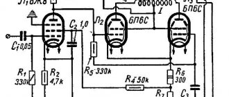
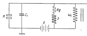
Anyone who is at least a little familiar with tube circuitry knows that tube amplifier stages are usually characterized by extreme simplicity and a small number of elements. This factor, along with the natural linearity of tubes, is usually cited as an argument when trying to explain the phenomenon of the superiority of tube sound over transistor sound. It must be admitted that such an explanation is very convincing from the point of view of common sense. In addition, it is so often confirmed in practice during circuit analysis of the best tube audio components that few people think of trying to challenge it. The main motto of the developers of lamp technology is this: the simpler, the better and more reliable (unfortunately, the concept of “cheaper” is not included here, although logically it seems to suggest itself). So, let's look at a conventional low-power resistive amplifier stage using a triode with a common cathode. An anode load resistor, a cathode self-bias resistor, a grid leakage resistor, and the triode itself - that’s, in fact, the entire cascade. More precisely, its basic version (Fig. 1).
Rice. 1
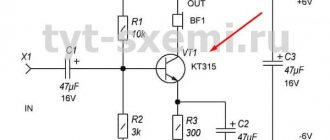
The rest is either communication elements with other stages, or blocking local negative current feedback (bypassing the cathode resistor with a capacitor), or a divider in the cathode circuit for a more complex organization of bias, or decoupling filters along the power circuits, or correction circuits. Typically, even the presence of all these additional components does not make the tube amplification stage much more complex than what we see in Fig. 1. Everything is extremely clear and simple (at first glance). It is known that the gain of the cascade in the middle of the frequency range is equal (in the absence of local negative feedback): K=-Ra/(Ri+Ra) (taking into account the input resistance of the next stage Rin.2 instead of Ra, Rn.eq=Ra|| Rin.2, and the output resistance Zout=Ri, where =SRi is the voltage gain of the lamp; S is the transconductance; Ri is the internal resistance of the lamp; Ra is the resistance of the anode load.
It is known that for such a triode cascade the real gain is usually (0.6-0.8) and depends on the value of Ra, as well as other parameters of the cascade: quiescent current, frequency band, slew rate of the output voltage, linearity, maximum undistorted output voltage , maximum output current. Usually Ra is several times higher than Ri, and it is possible to obtain acceptable values of the listed parameters. But the capabilities of a triode cascade are limited, and since in pursuit of one parameter other, no less important, parameters usually suffer, the degree of freedom to vary the values of the anode load resistance and cathode self-bias is small. The same can be said for anode supply voltage and quiescent current, since almost all tubes “sound best” at the edge of the permissible power dissipation at the anode (although not always). However, even within these relatively narrow “limits of creativity” it is not so easy to find the optimal operating mode for a particular lamp in a particular cascade, taking into account the previous and subsequent cascades. In this case, optimal means the mode that will provide the best sound, and not record-breaking parameters or beautiful waveforms. Perhaps it is the mutual contradiction of the various parameters of the amplifier stage and the ambiguity of their dependence on the same factors that are the reason for the weak correlation between the digital values of these parameters and sound quality. So, if you chase maximum linearity, you have to increase the value of the anode load, which, starting from a certain value, will negatively affect the frequency bandwidth, the dynamic properties of the cascade, and the gain factor, which, with an excessively large load resistance, begins to decrease as it decreases quiescent current and lamp slope. In addition, the overload capacity of the cascade drops sharply. Thus, the price for ultra-high linearity is also prohibitively high, since you have to pay for the sound quality of the device as a whole. It turns out that we pay in sound quality for linearity, and not vice versa, as it should be. This is reminiscent of Krylov’s fable “Swan, Crayfish and Pike”, only the swan in this case is not a bird (and not a general), but a gain factor, the crayfish is the linearity of the cascade, and the pike... In a word, things are still there. Where these intractable characters are in relative peace and harmony. Therefore, if one triode stage cannot provide the necessary gain, you have to install a second one. And in order to obtain good dynamic properties, sometimes you have to be content with a modest gain, reducing the value of the anode load and increasing the quiescent current of the cascade. Even in the simplest amplification stage, a lot of subtleties and difficult-to-explain phenomena emerge when it comes to the “last judgment” - listening.
So, let’s summarize: in an amplifier stage based on a tube triode, various parameters, each of which has a noticeable impact on the sound quality of the entire device, are in mutual contradiction, and excessive zeal in “pulling out” any one of these parameters inevitably leads to deterioration of others. However, there is a way to break out of this vicious circle. After all, so far we have been talking about an amplification stage on a single triode. What if you combine two triodes in the same stage? This, of course, goes against the concept of maximum simplicity, but sometimes, instead of increasing the number of simple cascades, you can solve the same problem by complicating (and not very significantly) one cascade. Depending on the specific task at hand, you can choose one of the options for such a complicated cascade using two triodes. I must say that there are quite a lot of them and they were invented a long time ago. For example, a cascode (Fig. 2) allows you to dramatically increase the gain and at the same time broadband, and therefore, along with pentodes, it has found wide application in television and radio receiving devices. Some world-famous High End companies also use cascodes in audio frequency amplification devices (for example, Sonic Frontiers).
Rice. 2
One can argue about the advisability of using cascodes in audio equipment, and opponents of this usually cite the fact that the output characteristics of cascodes degenerate from triode to pentode. Yes it is. But pentodes are not always bad - it’s not a question of what to use, but how and where. There is no doubt that in most cases the triode is preferable, but in individual circuits (most often auxiliary) the pentode has no equal. For example, thanks to high and Ri, the pentode has no equal in sources of stable current, except for field-effect transistors with an insulated gate. But this is a completely different world, and although firms such as Audio Research have achieved some success in the development and implementation of hybrid topologies, I personally have no doubt that if pentodes were used instead of MOSFETs, many of their products would sound would be much more musical. Let's remember the professional tape recorders of the golden era of magnetic sound recording in the 50s and 60s (for example, Telefunken). Many of them had an EF86 pentode (analogous to 6Zh32P) in the first stage of the playback amplifier.
But let’s return from attempts to amnesty pentodes sentenced to life by many audiophiles to immaculate triodes. The next cascade we'll look at is a lot like a cascode. These are also two triodes, one of which is “perched” on the shoulders of the other. Yes, this “lamp circus” causes a skeptical grin in many, and, probably, it may be followed by a stream of moralizing remarks like “a man - I beg your pardon, a triode - must walk on the earth!” But one way or another, this cascade deserves attention, since it provides a simultaneous tangible improvement in several important parameters: mode stability, linearity, output impedance, broadband, overload capacity and sensitivity to noise and ripple of the anode supply voltage. As for the sound, everyone knows that Audio Note and Saga Audio Designs amplifiers don't sound that bad at all! It is these companies that most often use the input or driver stage shown in Fig. 3a. It is most often called SRPP (Shunt Regulated Push Pull).
Rice. 3a
Do not be misled by the decoding of this abbreviation: “push pull” here is expressed only in the antiphase of the signals of the upper and lower triodes. With the same success, a classic circuit of two triodes connected in cascade could be called a “push pull” - there is also an anti-phase signal there. Thus, SRPP is not an entirely correct name that has taken root in the literature. You can also find the abbreviation TTSA (Two Tube Series Amplifier - a two-tube amplifier with sequential connection), although it can rather serve as a general label for all stages of a vertical configuration, including cascodes. In Russian, our cascade is called simply and clearly: an amplifier cascade with a dynamic load. And it is this name that most accurately reflects its essence (that rare case when the Russian language turned out to be more laconic than English). There is also a more exotic Russian name - a cascade with “electronic resistors” in the anode load circuit (T.V. Voishvillo. Amplifier devices. M., Svyaz, 1975).
So, instead of the usual anode load resistor, the SRPP cascade has a second triode in the anode circuit, the bias on the grid of which is set by resistor Rk2. When a positive half-wave of the signal appears on the V1 grid, the current of the lower triode increases, which leads to an increase in the voltage drop across the resistor Rk2, and this, in turn, reduces the current of the upper triode V2. There is a tendency towards stability of the anode current, which now depends on changes in the input signal to a lesser extent than in a conventional resistive amplification stage. The combined load - triode V2 and resistor Rk2 - in its properties begins to approach a source of stable current. What's good about this? It is known that a source of stable current has a high internal resistance, which for an ideal current source is equal to infinity (this, of course, is a mathematical abstraction). Now remember that the higher the load resistance, the more linear the triode stage is. It is not possible to solve this problem “head-on”, as mentioned above (by arbitrarily increasing the anode load), since other, no less important parameters of the cascade suffer. All that remains is to “deceive” the gullible triode V1, while its load resistance “bifurcates”: for direct current it is small and equal to (Rк2+Rivк2), which ensures the normal mode of the cascade without increasing the anode supply voltage, and for alternating current (or dynamic resistance load) can be much greater, and is determined by the value of Rк2 and the voltage gain of the upper triode: Rн. dyn.=Rк2(1+)+Ri(V2). This makes it possible to obtain a slightly higher gain of the SRPP stage compared to a conventional amplifier stage. And since the output signal is taken from the cathode V2, the output resistance is much lower. In reality, in the case when such a cascade operates at a relatively low-impedance load, a very significant gain can be obtained in both gain and bandwidth. And the dynamic properties, provided there is sufficient quiescent current of the cascade, can be obtained very impressive (here it is important to take into account not only the speed of the cascade, but also how large the signal current can be supplied to the load). For these reasons, the SRPP cascade found application in video amplifier circuits, where it was necessary to ensure the maximum value of the product, as well as in circuits of high-speed triggers (A.P. Lozhnikov, E.K. Sonin. Cascode amplifiers. M., Energia, 1964), probably , long before anyone had the idea to try it in audio amplification circuits. Its advantages are especially pronounced when working in circuits where the parasitic load capacitance is quite large (this category includes some driver circuits that operate on a large number of parallel-connected output lamps or on single lamps with a high dynamic input capacitance). In Fig. Figure 3b shows the dependence of the gain of the SRPP cascade on a double triode 6N3P (=35, Ri=5.8 kOhm) on the equivalent load resistance at various values of Rк2 (curve 1 corresponds to a conventional cascade with a common cathode, the rest - SRPP: 2 - at Rк2=360 Ohm; 3 - Rk2=560 Ohm; 4 - Rk2=820 Ohm) In Fig. Figure 3c shows the dependence of the output resistance of the SRPP cascade on the value of Rк2. In Fig. Figure 3d shows for comparison the transient characteristics of the SRPP cascade (above) and the conventional cascade (below) on 6N3P (curve 1 - at Cn = 5 pF; 2 - Cn = 15 pF; 3 - Cn = 30 pF; 4 - Cn = 55 pF) .
Rice. 3b
Rice. 3v
Rice. 3g
However, the SRPP is not the ultimate dream. And here's the reason: although the combined anode load of the cascade, as already mentioned, acquires some of the properties of a stable current source, but due to the relatively small characteristic of triodes, V2 does not have enough “amplification capacity” in order to sufficiently compensate for the drop voltage on Rk2 caused by a change in the signal current. This problem can be solved in two ways: either use a pentode rather than a triode as V2, or increase the signal level on the V2 grid. The first path leads to the diagram shown in Fig. 4, and the second - to the so-called “strengthened SRPP”, which also turns out to be more complicated (Fig. 5).
Rice. 5
The fact is that it is not possible to significantly increase the signal level on the V2 grid simply by increasing the resistor Rk2, since the position of the cascade operating point depends on the value of this same resistor, and if you get carried away with this method beyond measure, you can lose all the advantages of the SRPP cascade ( first of all, the overload capacity will deteriorate). But you can go further along the path of deceiving gullible triodes, “fooling” now V2: organize the required grid bias for it using a divider (Rk2 Ra), which will replace Rk2, which will give more freedom in varying the signal level on its grid (which will be proportional lower resistor of the divider), and apply this signal through the capacitor Ca. The gain of such a cascade can be made quite close to the lower triode (we must not forget that it remains the main “actor” that determines the operation of the cascade, and everything else serves only to create the best “working conditions” for it). Therefore, the amplified cascade of SRPP in foreign literature is called “Mu Follower” - “repeater”. And again, this spectacular name is somewhat arbitrary, since the amplified SRPP, although it gets quite close in gain to the value of the lower triode, still does not “repeat” it. In addition, it leaves the possibility of using a pentode as the upper tube and further complicating the circuit to further reduce the distance between the actual gain and the value of the lower tube, while simultaneously lowering the already fairly low output impedance and expanding the dynamic range. This cascade (Fig. 6) is called “(-cascade)” on the pages of the Glass Audio magazine (Allan Kimmel. The Mu Stage//Glass Audio, 1993, N2).
Rice. 6
The structural features of this cascade provide wide possibilities for choosing the quiescent currents of the upper and lower lamps. The currents in this case can be different, since the pentode bias is set by a separate divider (Rk2, R'k2), which also contributes to a further decrease in the output resistance (and, obviously, equalizing it for the positive and negative half-waves of a signal of a sufficiently high level, when " push-pull effect, i.e. the steepness of the leading and trailing edges of a rectangular pulse in the general case can be different). The value of the triode's anode load Ra can also be varied within certain limits. The pentode can be considered as a cathode follower with a transmission coefficient very close to unity. Thus, any change in the instantaneous voltage value at the anode, or lower terminal of the resistor Ra, is tracked with high accuracy by the cathode follower on pentode V2, appearing at the upper terminal Ra, and therefore the voltage drop across Ra is almost constant and does not depend on the signal - this and there is a real (not ideal, of course, but very close to it) source of stable current. Of course, those who suffer from pentode allergies can also use a triode as V2, but they will get more modest parameters. A triode cathode follower typically has a K gain of about 0.9, while a pentode can easily provide a value of 0.995 or even higher. Now let’s take the value of Ra equal to 6.8 kOhm and calculate the dynamic resistance of the cascade anode load: Rн. dyn.=Ra/(1-K). In our example, Rн. din. triode = 68 kOhm, and Rn. din. pent.=1.36 MOhm. The difference is 20 times! Cathode repeaters, by the way, also enjoy a far from impeccable reputation among technically competent audiophiles. But, nevertheless, as the same Allan Kimmel claims, in such a scheme, a cathode follower on a pentode is exactly what is needed. In general, pentodes in cathode followers give much better results both in terms of parameters (lower output impedance and attenuation) and in sound. In addition, Allan Kimmel writes that he experimented for a long time with all the tube cascades described above in all possible options, and all of them, when correctly implemented, sound very good, and the cascade is the best of all. It is especially good as a driver, “swinging” output triodes with small voltages that require a large signal voltage swing. The parameters of his cascade obtained by Kimmel (Fig. 7) are very, very impressive: output impedance 100 Ohms, output signal swing 215 V with a harmonic coefficient of 0.7% and anode supply voltage 300 V, level frequency range (-3 dB) 0. 28Hz - 1MHz.
Rice. 7
The triode is the well-known 6DJ8 (analogue of 6N23P), both halves of which are paralleled, which has a beneficial effect on the output resistance (as Kimmel writes, he also did this because he could not come to terms with the fact that one half of the triode was “hanging around idle” ). Pentode - 12GN7 (an analogue is unknown, but this is hardly important: any pentode with a sufficiently high , capable of operating at the required quiescent current, which is easy to determine based on the recommended current mode 6N23P, will do; 6Zh9P will certainly perform well). But that's not the end of the story. In Issue 5 of Glass Audio magazine for 1996, Allan Kimmel published an article entitled “A Direct-Coupled Mu Stage,” in which he presented an even more advanced work of circuit art (Fig. 8).
Rice. 8
It is difficult to say whether the idea of creating this cascade was his, or whether he borrowed it from old tube literature (after all, it often happens that many innovations actually turn out to be twice as old as their “inventors”). Be that as it may, the idea is very original: if the previous cascades resembled a “living pyramid” in a circus arena, then this one attracts aerial acrobats with a flying trapeze. The Ca capacitor has disappeared, the connection between the triode anode and the pentode control grid is now galvanic; At the same time, a floating stabilized power supply of the screen grid is introduced, and the triode anode also receives power from it. Initially, in this scheme the goal was to eliminate the Re Ce chain that “loads” the output of the cascade, although its influence was not any dramatic. One way or another, the parameter records of the previous stage (Fig. 7) were broken: the output resistance dropped to 80 Ohms, the maximum undistorted output voltage swing reached 269 V with a harmonic coefficient of 0.9% and the same anode supply (300 V), the frequency range for the absence of a transition capacitor Ca now starts from Fn(-3dB) = 0.15 Hz, Fv(-3 dB) remains the same: 1 MHz. In order not to rewind the power transformer, Kimmel found a very ingenious solution for organizing a floating source: he installed a small filament transformer and turned it on “back to front”, applying an alternating filament voltage of 6.3 V to the secondary winding, and connected a rectifier bridge and a simple transistor stabilizer to the primary winding , from which the required 75 V is removed. This non-standard method is also good because such a compact power supply can be placed in close proximity to our stage, thereby preventing the signal from “walking” along long connecting wires leading to a common power source. Although, if there is good isolation, this issue can probably be resolved in the traditional way - using a power transformer with a separate winding.
So, we looked at several tube circuits, each of which is characterized by a vertical configuration. There are other vertical stages, most notably complex cathode followers (such as the White cathode follower). Since in this case we were talking about voltage amplification stages, we will not touch on cathode followers in this article. This is a separate life with its own illnesses and medicines for them. In addition, the types of amplifier stages considered in many cases completely eliminate the need to use cathode followers, combining the properties of an amplifier and a buffer (just like the famous Pantin Pro-Vi shampoo with conditioner - two in one!). As often happens, each subsequent cascade has better parameters than the previous one, but at the same time it becomes more complex. Further into the forest there are more details. Therefore, I would like to advise those readers who decide to try something from this article “by sound” not to be maximalists and not to immediately aim for the “coolest” version of the above schemes, but to start with a simple one. Who knows, perhaps in a particular design of an amplifier or other device, some circuit intermediate in complexity and parameters will sound best. Personally, at first glance, the closest thing to me (so far only speculatively) is the SRPP circuit with a pentode.
Tags:
- ULF
Who needs a tube amplifier?
Here we come to the main thing
Who should pay attention to tube amplifiers? Well, firstly, not for those who always have music on in the background - the life of the lamps, as they say, is not endless. Secondly, for those who prefer a musical repertoire built on bass, the low-frequency range is not the strongest side of the “lamp”
Thirdly, it’s probably not worth combining “lamp” and computer music; there is no point in enriching the sound where nothing has been lost. Specific musical preferences are not so important; it can be classical, jazz or country - the main thing is that the music is acoustic. You will listen to it yourself or with your family, but without the participation of your neighbors. However, there are not many tube amplifiers that can create a dance atmosphere in a fully adult-sized living room. With the right choice of acoustics, of course. But this is a separate article.
Guitar Amplifier
Guitar lovers are often in search of high-quality sound, choosing the best option for a tube amplifier for self-production.
One of their guitar circuits can be assembled using four lamps.
To design you need to prepare:
- power transformer TPP 245-127/220-50;
- suitable output transformer;
- lamps 6P14P or 6P43P, as well as 6N2P;
- old housing or material for its manufacture;
- connecting wires;
- radioelements according to the circuit;
- a piece of foil PCB or getinax.
Step by step assembly:
- To manufacture the chassis we use a suitable housing. If you have sheets of duralumin or metal, you can make it yourself.
- The power board is made on PCB.
- We drill holes in the housing for the lamp panels, after which we install the circuit. It can be wall-mounted or on a printed circuit board.
- We twist the filament wires into a tight pigtail, and bring the common conductors to one point.
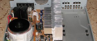
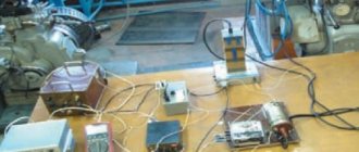
- After assembling the amplifier, you should get this type of device.
What it is?
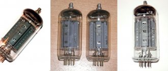
A tube amplifier is used to increase the power characteristics of alternating electrical signals using radio tubes.
Radio tubes, like many other electronic elements, have a very rich history. Over the years from their creation to the present day, there has been a serious evolution of technology. It all started at the very beginning of the 20th century, and the decline of the so-called “tube era” occurred in the 60s, it was then that the latest development saw the light, and soon more modern and cheaper transistors began to conquer the radio market everywhere.
The very first type of tubes created specifically for amplifiers were triodes. The number three in their name appeared for a reason - this is exactly the number of active outputs they have. The principle of operation of the elements is very simple: a source of electric current is connected in series between the cathode and anode of the radio tube and the initial winding of the transformer is made; the acoustics will be connected to the secondary winding that follows it. The sound wave is applied to the grid of the radio tube, at the moment when the voltage is applied to the resistors, a flow of electrons passes between the anode and cathode. The grid placed between them outputs this flow and, accordingly, changes the direction, level and power of the input signal.
During the operation of triodes in a variety of fields, a need arose to improve their technical and operational characteristics. In particular, one of them was the pass-through capacitance, the parameters of which significantly limited the possible operating frequency of the radio tubes. In order to solve this problem, engineers created tetrodes - radio tubes that had four electrodes inside their design; the fourth was a shielding grid inserted between the anode and the main control grid.
This completely satisfied the developers at that time; their main goal was to create a device that would allow receivers to operate in the shortwave frequency range. However, the scientists continued to work on the equipment; they used exactly the same approach - that is, they added another, fifth, mesh to the working design of the radio tube and placed it between the anode and the shielding mesh. This was necessary in order to suppress the reverse movement of electrons in the direction from the anode to the grid itself. Thanks to the introduction of this additional element, the process was stopped, thus the output parameters of the lamp became more linear, and the power increased. This is how pentodes came to be. They were the ones that were used later.
Peculiarities
From the point of view of the quality and character of the sound, each type of lamp and each switching mode has its own characteristics, so obvious to the ear that even the ultra-linear mode, in fact, did not become the golden mean. Pure triodes and triode inclusion of pentodes provide the clearest and most spacious sound until it comes to energetic music with fast and significant volume changes. In other words, triodes are much better suited for calm jazz than for listening to rock.
Pentode and ultralinear modes, on the contrary, are more suitable for energetic music, but in some cases they do not sound clean, accurate and detailed enough. These complaints especially often relate to the pentode mode, and in general the sound character of both the pentode and ultralinear modes is often compared to transistor amplifiers.