6p45s - in LUMZCH, this is quite serious
The article is devoted to some features of building an amplifier using the most powerful and relatively small-sized lamps from the series known as “television”. The text contains a significant amount of reasoning on related topics. Oddly enough, it is the adjacent areas that are extremely important for ensuring the resulting quality of the amplifier. For example, it is the matching transformers that radically influence the sound, and not the lamps at all. Serviceable tubes have virtually no effect on the sound amplification characteristics. However, the lamps look beautiful and glow in the dark. And this is probably why the names of the lamps give the impression of decisive signs of the quality of the product. Already in appearance, the solidity of the pot-bellied glass cylinders 6P45S is noticeable. Taking into account the power reserve traditional for Soviet lamps, it is possible to build a push-pull amplifier in which the anode dissipation can be increased to 45-50 watts. With such a large dissipation, the heat release will be enormous. This is of course a drawback. But, according to the GURU, the sound quality in modes close to A can be obtained excellent. My attitude towards such extreme is cautious. I am not a supporter of mode “A” in a tube amplifier. The second inconvenience of the 6P45S can be considered the upper location of the anode terminal. In addition, the filament current is 2.5 amperes and the lamps heat up very much, which is also inconvenient. Therefore, a structure with a mesh-covered top, or at least with crossbars, should be provided. For heat removal, we can recommend the use of low-noise computer fans at +12VDC, with automatic switching on when the case heats up above 50 degrees.
Given the considerable power of the selected lamps, you should pay close attention to the design of the power supply. It should be noted that the traditional frivolous attitude of many TV viewers towards the power source of a tube amplifier is not suitable. The amplifier's power supply is its power plant, the core of its design and the source of all its success. The power plant must be created extremely thoroughly and precisely according to the block principle. And novice lamp manufacturers need to learn how to quickly and accurately calculate the required power of power transformers. It is better to focus on the maximum consumption mode and approximately calculate the total power of the transformer windings. First you need to calculate the power dissipated at all anodes. In maximum mode, 4 lamps can dissipate 40x4 = 160 W. Small lamps dissipate 4-6 W in the anodes. Then you need to add to the heap the power that is planned to be sent to the load, for example 50x2 = 100 W. The incandescent circuits of powerful lamps consume 2.5x4x6.3=63 W. Small incandescent lamps will consume 12-14 watts. In total, the resulting consumption is 260+75=335 W. The design efficiency of a two-channel amplifier does not exceed 30%.
The power of power transformers can be reduced somewhat, since the maximum mode is used extremely rarely. When designing transformer power supplies, the large overload capacity of transformers is taken into account. For this reason, this is what they usually do when creating serial amplifiers, reducing the installed power of the power supply by 20-30%. This solution is quite permissible, but for high-level amplifiers manufactured in single copies, it is better not to do this. In addition, it will not be possible to reduce the filament power, since heat losses cannot be deceived. You should not overestimate the installed power of transformers, since this unjustifiably increases the weight of the product. Remember, with the calculated power value of the power supply transformers, the resulting ratings correspond to high operating temperatures. Therefore, transformers heating up to 60 degrees should not be a surprise to the designer. If the viewer has the idea in his head that the iron should be cold, then all powers should be doubled and prepare for the fact that the weight of a 15 W amplifier will become 35-40 kg.
In my opinion, the most promising circuit solution for push-pull tube amplifiers of high energy efficiency should be considered a matching stage on a differential pair of transformers. The advantages of such a scheme completely cover its disadvantages. I attribute any discussions about hand-to-hand winding of matching transformers in a tube amplifier to perfectionism. To me, this seems to be one of the designer's self-consolation methods or one of the marketing steps in justifying the extreme cost of the amplifier. Self-winding is a harmful excess and stupidity. In itself, hand-to-hand winding of transformers into a push-pull amplifier is not a technically difficult task. But making a symmetrical pair is no longer an easy task. Manually manufacturing identical four transformers for differential series connection is an unimaginably complex project. For single-ended amplifiers, the creation of symmetrical trances is possible, since using Ignatenko’s technology, it is possible to use hammer tapping when adjusting the air gap on the glue at the joints of the cores. The characteristics of iron for transformers with a gap are not particularly important, since the gap dampens the magnetic properties of the core by 1000 or more times.
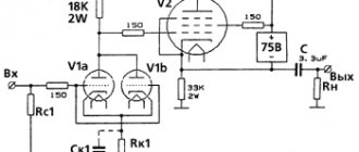
An example of a first level diagram is shown below. Here the anode voltage is quite high, and the grids are connected according to an ultra-linear circuit to the symmetrical 42% taps of the transformer windings, relative to the center of the +330 volt anode supply. This is not good, since according to theory, the second grids should have a lower voltage than the anodes. But in practice, such inclusion, along with the advantages of the ultralinear scheme, may have a drawback - the occurrence of additional distortions described by Ignatenko. Therefore, you can consider an alternative version of ultralinear inclusion according to a different scheme, shown in the article below. A special feature of these particular circuits is the inclusion of an output stage driven by cathode followers. Fans know that television lamps are low-sensitivity. Therefore, you have to resort to additional tricks, use preliminary stages with dynamic loads, or install additional powerful drivers. The use of a circuit with direct connections somewhat complicates the setup, but allows you to avoid the use of decoupling capacitors. Practical repetition of the circuits shown here should be performed using 6N1P lamps, with carefully selected halves according to the condition of symmetry. Yes, and the output lamps in this version must be selected according to the bias voltage. There are general recommendations for building high-level push-pull amplifiers. You need to use symmetrical lamps, and there will be significantly less hemorrhoids. And in these specific schemes this is no longer a wish, but a requirement.
There are no gaps in highly efficient matching transformers, so the result depends only on the quality of winding, the equality of turns, the quality of assembly and the nonlinearity of the iron characteristics. The last two conditions are extremely difficult to achieve in reality. Here, right off the bat, you need to assume a discrepancy in operating parameters of approximately 10%. And this discrepancy can be established in practice only by measuring the finished product. And when a discrepancy is discovered, the finished trance can be safely thrown into the trash, since such a discrepancy will not allow building an energy-efficient amplifier. To require pinpoint precision, you can take the path of selecting symmetrical pairs from a bunch of bourgeois output transformers, but it’s hard to even imagine how much money this will cost. You need to understand that a very good result in an amplifier is given by a discrepancy in the load characteristics of transformers of no more than 2-3%. Moreover, it is curious that such a difference in currents XX does not at all guarantee the equality of the EMF of the windings when connected in series! This feature is described in my method for selecting transformers, here on the website. As a rule, out of 4-5 transformers with approximately the same no-load current of 10-12 mA, only two products produce a symmetrical pair. The rest differ by 8-10% and you have to select a pair from adjacent values of 8-10mA or 14-16mA for XX currents.
The explanations presented here show the depth of the abyss on the way to building a high-quality and energy-efficient amplifier with a differential pair of matching transformers at the output. If the requirements for symmetry are somewhat roughened, for example to 15-20% divergence of the EMF, then the selection of pairs is much easier to perform. At the same time, at the stage of setting up the amplifier, the curvature of the operating system with respect to alternating current must certainly be corrected by hand-to-hand adjustments to the instruments. It will not be possible to find a direct connection with the quality of sound amplification here, since there is none. Don't think that an amplifier with crooked transformers will sound much worse. You won't notice this by ear, even at medium power. Tube circuits, as a rule, are self-balanced and easily tolerate curvature. And the adjustment allows you to equalize the characteristics of the sound path. You just need to be aware that the maximum operating parameters of such a design will actually be lower. For example, a car with the inscription Bugatti will not go at a speed of 299 on the highway to Abakan. The available speed limit will be only some 150 km/h. I declare with full responsibility that blind listening to amplifiers with lamps operating in different areas, even very different operating characteristics, will not be reliably identified by experts. There are no such people who distinguish between different spectrums of harmonics, beautifully mixed within the musical range. Using instruments, it is certainly possible to determine the difference in spectral composition. But only by instruments. Therefore, for experts, all that remains is to smack their lips and shake their heads, saying they like this and don’t like that. Moreover, it is not a fact that specific people with a damaged worldview will like a more even frequency spectrum, without outstanding harmonics.
Beginning designers should remember that in reality the situation is even simpler. If the requirements for the product are reduced even further, then when setting up the amplifier, it will be possible to straighten the more significant curvature, or at least smooth out its consequences. In this case, the lamps themselves can also be crooked. But even using clumsy light bulbs, you can push them to different performance characteristics. At the same time, being in curved modes, the lamps will be able, within reasonable limits, to deliver the power of an undistorted signal to the load, quite sufficient for comfortable perception of sound. The difference is easy to see in the comparison shown below. A beautiful and compact Chinese jack with the inscription 12 tons, made without tricks, will easily lift the Kukuruzer, but it should not be used for Kamaz. After all, he will lift the Kamaz only once. And if such rigorous testing is not done, then the driver of the Kukuruzer will be satisfied with the small Zhiguli dimensions of the jack and the inscription 12 tons and will never know the reality. This is ordinary marketing, oh, a typo in the text, this is ordinary deception.
An example of a second level circuit is shown below. The division into levels is, of course, conditional; the output transformers are exactly the same. The number of windings is fixed. And whether to adapt these windings for cathode OS or grid windings is a matter of taste. The main thing is to perform error-free desoldering, for which there is the usual “scientific poking” method. A properly assembled and operational amplifier is quite sensitive to transformer feedback, so any incorrect activation can lead to a sharp deterioration in performance. And there is only one option for correctly switching on the windings. This is what you need to detect when setting up an amplifier with OS.
In general, we can conclude that the 6P45S lamp is an excellent motor, suitable for building a dynamic and almost omnivorous amplifier. It is absolutely possible to double the tetrodes to increase power. We must be very careful with the authors of pictures in which, instead of a classic tetrode, a 6P45S lamp is depicted as a pentode. This is the wrong image. This is where we should proceed in assessing the reliability and resulting authority of the circuitry and the author’s reasoning. In continuation of this article, another article is planned on the site - about the features of selecting 6P45S lamps.
At the end of the presentation, I dare to assure you that all the hardware described on the site can be purchased for rubles. In order to buy a 6P45S amplifier at a price starting from 45K, the buyer simply needs to negotiate with the seller, preferably in Russian. The algorithm for fulfilling obligations under supply (purchase and sale) agreements is as follows. The interested party calls me by phone at a reasonable time in the Krasnoyarsk time zone. We are actively discussing the details of the contract. Then the buyer credits a payment of 1% of the purchase price to my phone number. This serves as a sign that the buyer is serious and allows me to promptly call back if necessary. After a telephone discussion, I send a commercial proposal to the partner’s email, with product characteristics, warranty obligations and delivery times. Next, negotiations are completed through correspondence and the buyer transfers 20% of the purchase price to my account. The remaining 79% of the amount is transferred to the supplier’s account after the buyer receives notification of readiness for delivery. Please remember, prepayment for glands is 100%. Therefore, the buyer can immediately transfer the entire amount, already at the first stage of correspondence, but only after my written approval. There are no movements on my part without advance payment. Advice is free. Delivery of pieces of iron by Russian Post or transport company at the buyer’s expense. Pickup is possible by arrangement. If the buyer refuses the transaction, no refunds will be made.
Evgeny Bortnik, Krasnoyarsk, Russia, November 2022
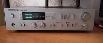
Amplifier based on a “television” lamp 6P45S
I recently pulled out my old 6P45S tube amplifier from the garage. I wanted to try connecting the Flex-1500 SDR transceiver to it (until the transistors for the Italian HLA-300 arrived).I started working on air with this amplifier as my personal call sign in the late 80s. For several years, the amplifier worked together with a homemade Radio-76M2 transceiver, and later (after a slight modification) with an industrial device Efir-M. During this time, many thousands of QSOs were made (most of all on the 160 m band).
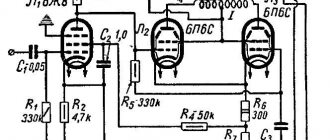
The amplifier was assembled according to the hybrid circuit of V. Zalnerauskas (UP2NV)
from Radio magazine No. 4, 1986.
Hybrid amplifier circuit
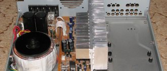
The amplifier housing was purchased at a DIY store and was clearly designed for a powerful transistor ULF. I must say the case turned out to be heavy and durable, made of rather thick metal.
To begin with, I divided the case with a shielding partition into the high-frequency part and “everything else.”
There is a lot of free space inside the amplifier - the case is too big
For the power supply, a power transformer from TS-180 black and white TVs was used. The anode voltage was supplied to the lamp from a rectifier with doubling the voltage. Instead of the KT922 transistor, I installed the KT909 (which was at hand at the time). The pre-amplifier was placed in the body of the Radio-76M2 itself and was assembled using KT325 transistors. The amplifier was not photographed before the conversion, so there is nothing to show. In the first version of the P-circuit, instead of a KPI there were two biscuits that switched mica capacitors of different ratings, and instead of a coil there was a ball variometer. The P-loop was built well on the 160 and 80 meter bands. With the advent of Efir-M, the circuit was redone according to the classical scheme - two KPIs and a coil with switchable taps. I used an antenna relay from some military equipment - large and powerful (I even built a separate diode bridge to power it, but in fact, RPV-2/7 would have been enough).
The amplifier worked successfully in the low-frequency ranges, but at 14 MHz and above, the anode current, when a signal was applied, increased as expected, and the output power dropped rapidly with increasing frequency. Then I wanted to try the classic version with a common cathode and swing into a grid. The boost was supplied through a 1:3 step-up transformer (1:9 in resistance) to a 510 Ohm resistor in the first grid circuit.
The modification made it possible to work on all bands with a slight decrease in output power on the ranges of 21-28 MHz (I didn’t seriously think about a good SWR at the amplifier input at that time).
After many years of neglect, the amp was turned on, and as the tube warmed up, a faint, nostalgic “tube” smell appeared.
To begin with, I connected the FT-817 transceiver to the amplifier and discovered (using the built-in SWR meter) that in the low frequency ranges the matching at the amplifier input is very good, but starting from 14 MHz it begins to quickly deteriorate (the input capacitance of the lamp shunts the input).
I slightly modernized the input circuit - instead of a 1:9 transformer, I soldered 1:4, and replaced the resistor with 200 Ohms. The matching on the HF bands has become noticeably better; at 10 the transceiver stopped complaining about high SWR, but it’s still far from ideal.
The next step is to try to plug in a low-pass filter loaded with the same resistor after the transformer, so that the capacitance of the lamp control grid becomes part of the capacitance of the filter itself. This trick should significantly improve matching on high frequency bands.
The amplifier, when pumping 100% power with the Flex-1500, produced about 100 W on the 80-meter range, 80 W on twenty meters and 60 W on ten in carrier mode. The signal quality turned out to be good; the correspondents did not detect any nonlinear distortions.
RN1NEB
info — 28600.ru
PS
Some quotes from the forum:
RA1N (Andrew)
:
“Oleg, haven’t the electrolytes dried out?” moder
:
“Old Soviet electrolytes of this type are of very good quality and hold their capacity for a long time, and if they sag, they are completely restored after a short workout.” rn1neb
:
“They haven’t dried out at all, just like new!
There was a desire to install the second TS-180 and the second lamp in parallel (only then it would not hurt to increase the number of ventilation holes above and below the lamps), and at the same time avoid doubling the voltage and make a normal bridge rectifier. You also need to wind the “tenth” coil of the P-circuit with a thicker wire. Now I’m thinking... should I leave it as a museum exhibit, or should I modernize it again? I have a couple of new bulbs, but they say that 6P45S bulbs are very different, it’s difficult to find two identical ones. Of course, you can make separate adjustments to the quiescent current (although this will not solve the problem 100%). Or maybe it's not so scary after all? People work on the air even with 4 6P45S in parallel.” Check out the VK radio amateurs group: https://vk.com/ra1ohx Share the post on your social networks!
- Hybrid linear power amplifier
- Wideband amplifier KB radio station of the 2nd category
- Hybrid voltage stabilizer of screen grids of lamps of the final stage of a radio station of the 1st category
- Setting up a hybrid stage
- Two-stroke RA on 6P45S
- RA on lamp GU-13, 6P45 or GK-71, GU-50
- Balancing device
- Transformerless RA on GU-29
When copying material, a backlink to our website is required!
Tube amplifiers, methods for selecting output transformers
The article outlines the procedure for selecting unified transformers for push-pull tube amplifier circuits (circuit announcement from S. Komarov in Radio magazine, 2005). Differential connection of output transformers is subject to consideration. The article was written primarily on the problem of building high-quality push-pull tube amplifiers with high power. The problem of increasing the power of a high-quality tube amplifier can be solved by using special output stages with dual transformers. This connection of transformers is called differential. The output transformers must have a split primary winding.
The peculiarity of differential connection is such that the primary windings of two transformers are connected in series. The secondary windings of two transformers are combined according to circumstances, for a specific circuit and very specific operating parameters. Double power can be taken from two transformers. Or you can interpret this idea differently. The use of two transformers instead of one reduces the magnetic induction in the iron. From two transformers included in a single harness, you can get twice the number of extremely useful additional windings. And it is these windings that can be used to provide sectioning, as well as use combined feedbacks that increase the linearity of the audio path. Well, a completely obvious idea. Doubling the number of matching transformers results in doubling the equivalent inductance. And this is the simplest sign of a sharp decrease in the lower limit of the amplifier bandwidth. Here's a surprise for you! The switching circuit for the push-pull output stage of a tube amplifier is somewhat modified and becomes cross-linked. But the need to maintain symmetry is quite clearly evident. A careful examination of the circuitry of differential output stages has shown that it is quite simple to implement ultra-linear connection of standard industrial transformers, while achieving extremely high quality indicators of UMZCH, at relatively low costs. All that remains is to adapt the most common types of unified transformers to the output stages. A lot of research and, accordingly, a significant part of the articles on my website are devoted to solving this problem. It is very good if the designer has many identical unified transformers at his disposal. It is possible to select suitable copies.
The problem of differential connection of transformers is part of a more general problem - the sequential connection of windings belonging to different transformers. Since the transformer is a nonlinear element, its current-voltage characteristic has a characteristic curved appearance, with a clearly defined saturation knee. At the same time, the characteristics of all transformers differ from each other, even if insignificantly, but they differ. The current-voltage characteristics of transformers have different slopes in all areas. And since when two windings of different transformers are connected in series there will be one common current, the voltages on the windings will be different! In other words, if two different windings are connected in series to a 220V network, then one transformer may have 80 volts, and the other 140 volts. Moreover, the XX mode is characterized by one operating point. As soon as the output windings are connected, the operating point changes its position. If you load only one output winding, the asymmetry will increase even more. If you load two windings, the asymmetry may decrease. Connecting the output windings in series does not significantly level out the circuit mode. But the parallel connection of the output windings somewhat aligns the mode with the input, slightly pressing down the magnetic flux in the core. In any case, sequential connection of the windings of two different transformers is EXCLUSIVE. To equalize the primary voltages, a selection of transformers is absolutely necessary.
Practical confirmation of the difficult situation with series connection of transformers is the absence of a description of such a task in the literature. There is no such topic in textbooks at all! There is no such topic in the minds of sensible people. Consideration of such a topic may arise precisely in the example of differential connection of the output transformers of a lamp UMZCH.
Beginning designers of tube amplifiers need to understand that the distance from an attractive table of output parameters of a tube amplifier, with powers of 50, 100 and 200 W, to its implementation in hardware is quite large. Tube amplifiers with differential connection of output transformers (S. Komarov, Radio magazines 2005-2006) have an indisputable priority among others. This is an obvious fact, since they really meet the high requirements for Hi-End class equipment and provide not only colossal power. They have a wide frequency range due to the significant output inductance caused by the actual use of dual transformers in one channel. It should be remembered that in differential circuits, armored transformers designed for a voltage of 127/220 volts, or rod transformers for 220 and 127/220 volts are applicable, as shown in the figure below. It is necessary to fulfill a fundamental condition, to ensure the presence of a split primary winding.
A limiting factor in the widespread use of LUMZCH differential circuits is the requirement for careful selection of output transformers. This requirement exists and its implementation is mandatory. Otherwise, in terms of alternating current, the circuit may turn out to be lopsided. The utilization rate of light bulbs may be at the level of 20%, which reduces the advantages of the differential circuit to minuscule. S. Komarov is aware of this requirement, but they avoid talking about it. It should be remembered that fulfilling this requirement is of fundamental importance for the design of a serious tube amplifier with a high power utilization factor. To build low-power “farts” you don’t need to know the topic. You can continue to play children's games with vacuum tubes, without even realizing that using transformers with a size of 0.25 kVA to build an 8-watt amplifier, for example, on 6c33c or EL34 light bulbs is simply ridiculous. The general diagram for connecting a differential pair of transformers to a tube amplifier is shown below. These are two different effective options for switching on TPP transformers. Moreover, you need to remember that for rod and armored transformers the pin markings are different.
It is very convenient when the number of symmetrical windings is quite large. This allows you not only to flexibly vary the load resistance, but also to alternate the anode windings, improving magnetic coupling, and also to use part of the windings for cathode and grid feedback. An example of a transformer built on the basis of the well-known broadcast amplifier Resprom is shown in the figure below. This transformer without rewinding is suitable for current lamps of type 6P44S.
An example circuit for TN type transformers is shown in the figure below. Despite all the apparent complexity of the schemes at first glance, they are actually very simple and even trivial. At least competent wiring will certainly put everything in its place. And fans of winding procedures, not only young ones, but even elderly fans, who contemptuously call the unified transformers “green stuff,” nervously smoke and relax on the sidelines. It's sad, but it's a fact. Unified transformers are really unsuitable for classical inclusion in push-pull circuits. And this border stops people with limited horizons. But differential circuitry easily pushes this limit back. You just need to master new knowledge, no matter how difficult it may be.
The selection of output transformers is performed in a certain sequence. It should be noted right away that no manipulations with winding the output transformers manually are suitable here; homemade ones can relax. As the text of the selection methodology presented below will show, craftsmen should forget or throw the acquired winding skills in the trash. Because it is impossible to manually ensure high repeatability of winding units. Ready-made transformers are not bad at all, but very convenient.
First, the no-load current is measured for the transformers of the entire heap at a constant mains voltage of 220 volts. The recorded current value is signed directly on the transformer. Transformers are placed in a row as the current increases, and nearby transformers are taken for further comparative measurements. It is desirable that the current discrepancy does not exceed several milliamps. This is the first stage of selecting transformers.
At the next stage, the primary windings of the transformers are soldered according to a differential connection scheme (three wires in total). Find a common point when crossing the 127 volt taps. An adjustable voltage from the latr is carefully applied to the outer terminals. If the wiring is incorrect, then the current when regulated from the latre will increase sharply. With correct phasing, the current of four half-windings connected in series to a 220 volt network will be very small. It is during this desoldering that further measurements are performed.
At the third stage of selection, to achieve differential switching of a pair of transformers, the EMF of the same windings of each transformer is measured using an ordinary tester. Even with the same initial no-load current, the EMF of transformers can differ by 20-50%. If the discrepancy is large, then the transformer with a lower idle speed is replaced with another one that is closer in current and the measurement is repeated. If the selection fails, then vary the transformers with the nearest higher current value XX. Leveling the EMF to 5% can be considered suitable. When selecting a pair, pairing transformers with a divergence of no-load currents of 10 mA or more is pointless; symmetry cannot be achieved.
The fourth stage of the test is to compare the voltages on the halves of the primary windings of the transformers connected in series. These voltages must also be identical with a fairly high accuracy. Experience shows that from a bunch of 50 powerful serial transformers TN or TPP you can find 5-6 pairs of symmetrical transformers with an accuracy of up to 1%. However, selection based on idle speed parameters is not sufficient. It turned out that selection under load is important for reducing the distortion level of a loaded amplifier. The fact is that at the idle point the parameters may coincide. And due to the different quality of steel and especially the quality of fit of the cores along the gap, the Weber-ampere characteristic may turn out to be of different steepness. So you need to check the symmetry more carefully, check it under load.
At the last stage of selection, the voltages of the same windings of a pair of transformers under load are compared. To do this, the secondary windings of the differential pair are connected in series and loaded with resistive current up to 50% of the rated current. Moreover, transformers are loaded by at least 30% of equivalent power. It is advisable to connect windings with the same rated current in series. In this mode, the difference in voltages of windings of the same name can be considered acceptable to be no more than 5%. The achieved degree of symmetry allows us to consider a pair of transformers suitable for a tube UMZCH of objectively high quality, very high and quite high power. An example of perfectly matched pairs is shown below. The initial no-load current of each transformer is 10mA. The selection accuracy is really high and the discrepancy does not exceed 1-2%. Dear TV viewers, I will repeat an important consideration. When carrying out measurements, you need to control the level of mains voltage. It's winter now and it can float, even for a minute. People and automation sporadically connect powerful heaters, and the networks in apartments are weak. Therefore, I use LATR, periodically look at the voltmeter and adjust the LATRA slider during voltage dips and surges.
Seasoned radio amateurs, I think, will immediately understand the meaning of the material presented. But insolent and illiterate “old men” can get angry at such chatter. To which I can answer with simple facts. For me, clear confirmation came from the messages of one out-of-town radio amateur. Apparently, a very middle-aged radio amateur who went through the school of transistor electronics, as well as industrial projects. So the meaning of this message is as follows. The man tried to use my method to select a couple of transformers from his stocks. And he was shocked by the result. It turned out that out of 10 transformers of the same type, he was unable to find a symmetrical pair for Komarov’s circuit! Here's reality for you. Try to wipe the moisture under your nose and choose your own transformers, try any scheme from Komarov. Then there will be a reason to re-read my posts on the site. An even more significant comparison can be made. The selection of differential circuit transformers is more complex than the use of symmetrical transistors in the differential input stage, but no less important. For smooth input differential stages, special microassemblies with obviously symmetrical transistors on a common chip are used. This is the norm, and nothing else occurs to anyone, since everything else leads to a crooked result.
Sometimes you get your hands on unique transformers. Here, for example, are English toroidal transformers with a size of 0.2 kVA. The pair is not enough for a differential output circuit, but for the classic two-cycle on 6C33C triodes they are amazingly suitable with a reduced resistance of about 1.5-2 kOhm.
The use of serial armored transformers, selected in a similar way, as output transformers in LUMZCH ensures the maximum possible use of the output lamps of the push-pull stage and allows them to be driven into modes that are 20-30% or more higher than the nominal ones.
And this is with minor distortions. Particular attention should be paid to the traditional recommendations and preferences that authors usually write at the end of articles. The most important line should be considered: The amplifier must be assembled from serviceable parts . The amplifier must be assembled according to the ratings indicated in the diagram. Recommendations for the accuracy of selection of denominations also indicate, and often the requirements are excessive. In the vast majority of cases, in a tube amplifier, the use of parts with a deviation from the nominal values of 5-10% is quite acceptable and normal. A large number of speculations, important pouting, and sometimes even hysterics are associated with the rigidity of the implementation of the insane requirement - the mandatory use of resistors in the accuracy class of 1-0.5%. This is obvious stupidity. And whoever does not want to understand this, let him attribute it to a marketing show-off to increase the price of the product.
It is necessary to select one or two values in a lamp circuit with high accuracy. Moreover, you need to select not according to the inscription on the diagram, but you have to select according to the place (according to the mode), based on the condition of ensuring the minimum possible distortion of a particular amplifier stage. The brands of the individual components used do not matter. No advertising of individual brands of capacitors or resistors should be given in articles. Only fools advertise other people's hardware and other people's brands for free. If you come across even a good article in which, when describing his own design, the author piles up a bunch of recommendations about the use of certain capacitors or resistors, then you just need to know that this author is a fool. Or perhaps the author is pursuing a crafty marketing goal for which he was paid or planned to receive his own income from this advertisement hidden in the article. The photographs below show sets of Canadian transformers that are quite suitable for push-pull circuits, since the primary winding is split, and each half is designed for a nominal voltage of 115 volts. The overall power of the iron is 48VA and 70VA, respectively. It is the sign of splitting of the primary winding that serves as a criterion for the applicability of a transformer for a push-pull tube amplifier. However, we should not forget the second key condition of applicability. Namely, the no-load current of such a transformer should be negligible. For example, you can roughly estimate the inductance of the primary winding of a trance in a 50 Hz network. Knowing the voltage and current of the XX winding, it is easy to calculate L for the cyclic frequency 314, taking into account that the value of R is incomparably small. If the resulting inductance value is less than 15-20 henry, then the transformer will not satisfactorily reproduce the low-frequency range. And the purpose of such a transformer is in power circuits, and not in sound.
Using the bourgeois transformers shown, you can build wonderful low-voltage differential stages. Initially there were quite a large number of them and they were purchased almost at the price of scrap metal. However, a significant part of this iron has already been sold, as they say on the vine. People are gradually understanding the meaning of the material presented in my articles. It can be noted that in people’s lives there are other, quite obvious things that it is high time for people to understand (for example, A. Fomenko’s New Chronology). However, the degree of brain congestion with garbage is high. Objectively, there is a great amount of brain foulness and this is sad.
Achievable powers for tube UMZCHs when constructing highly symmetrical push-pull differential circuits can be considered values of 80-100 W. It is better to limit the anode voltages of differential circuits (TN, TS, TP, TPP) at the level of 400-500 volts. Increasing the anode voltage up to 800-1000 volts can only be tried when moving to symmetrical differential circuits, on TAN transformers selected in the same way. Additionally, it is worth mentioning the arguments of forum members, which are often found on the Internet. For example, about the alleged discrepancy between the parameters of Komarov’s circuits and those stated in the technical characteristics articles. I dare to assure the reader that in an amplifier assembled from serviceable parts using a differential circuit, if the output transformers are selected according to the condition of symmetry and correspond to the correct pinout, the tactical and technical characteristics of the audio path fully correspond to the declared ones. And before you talk about the shortcomings of Komarov’s schemes, you just need to wash your hands as usual, your beloved. Negligence and disregard of scoops in assembling circuits are present everywhere and almost always. Therefore, before you grunt, you first need to overcome the soviet mentality and just try to create something of your own, your own. Sergey Komarov is just a great guy. He did an important job. He built a trough for the crowd and poured food into it. And what happens next depends only on the scoop. Either feed from this trough or shit in it, decide for yourself. The main criterion for creating an amplifier using circuits with differential connection of transformers is thoroughness. Selection of a differential pair of output transformers is mandatory . First, the block of output transformers is completely assembled and correctly soldered. Then it is tested under voltage, checking the correct phasing of all windings and fixing the color designation of all wires along the twisted pairs, because there are quite a lot of them. Only after this the block of output transformers is exported to the structure of the mounted amplifier. I strongly recommend doing the same when designing a power supply. First, a monolithic structure of the power supply is assembled, with all the transformers, capacitors, chokes and other tripe. The power supply is then configured and tested under load. Only after this the finished power supply module is exported to the amplifier housing. Remember that in reality the design of a large tube amplifier is quite complex. And Internet photographs, with a snotty mess or with a geometrically correct installation from the Guru for three capacitors, inside an empty amplifier case, are children's toys. In reality, there is always not enough space inside the case; there is always just enough space! Therefore, the structure has to be carefully designed in advance.
It is extremely important to make one more remark, which will allow TV viewers to more adequately imagine the real power of tube amplifiers and distinguish the actual state of affairs from fiction. The nonsense with Chinese watts begins solely as a result of marketing moves. This is a bait for fools. In lamp technology you should also remember simple rules. For example, the useful power of an amplifier cannot be greater than the active power dissipated at the anode of the lamp . So, if the amplifier is assembled using two 6P14P lamps, then its power cannot be more than 14 watts. It's like a Zaporozhets car. Well, it can’t develop power and speed like a Bugatti. CAN NOT! That is why achieving colossal lamp powers of 100 or more W requires parallel connection of selected output tetrodes or pentodes. It should be remembered that Sergei Komarov knows this rule. And when he writes articles about a tube amplifier with a pair of TN61 output transformers (200 W each), he knows that the power of such an amplifier cannot reach 400 W, i.e. double the power of 200W transformers, if these transformers are powered by just a pair of EL34 lamps. 400 W in this case is the power of the iron. Power in acoustics cannot come from nowhere. Obviously, to increase the traction of a vehicle, it is necessary to increase the power of the motors, their number or size. Instead of 6P3S you can put GM70. Or use parallel connection of carefully selected 6P3S lamps, 3-4 pieces per arm. Therefore, behind the tables with wild transformer powers of push-pull tube amplifiers, Komarov hides the parallel operation of the light bulbs shown in the article. Or you need to switch to larger light bulbs.
In the practical construction of a conventional tube UMZCH, output triodes should be avoided. These are show-offs and hemorrhoids compared to output tetrodes and pentodes. In a high-class and high-power amplifier, ultralinear, super-pentode or super-triode connection of output tubes is preferable. For dual, triple or quad high-power output pentodes, you cannot stupidly add the powers of parallel lamps. There is always the effect of weakening the equivalent power. After all, the current-voltage curves are curved, the modes are not 100% consistent, and the phase discrepancies are enormous. It is the Chinese who use bad power figures for their amplifiers. Wild powers in inscriptions are obtained very simply. Take, for example, the short-circuit mode for a power source, in which it consumes 3 amperes from the network, then the power of the device can be easily calculated using the formula 220x3=660 watts! This is how you get a 660-watt amplifier. This is one of the marketing tricks for unscrupulous buyers.
Adults , stop believing in fairy tales, leave this pleasure to the children .
Evgeny Bortnik, Russia, Krasnoyarsk, January 2016
Plasma on the lamp head
Hamsters welcome you, friends!
Today's post will be dedicated to the torch discharge generator based on the most common Soviet-made radio tube, 6P45S. The torch here is formed due to a high-frequency electrical discharge, which at normal atmospheric pressure resembles the flame of an ordinary candle. Except that the temperatures here are simply enormous. Plasma after all. During the story, we will learn how to assemble such a device, look into its inner world and find out what factors influence the performance of the circuit. According to the classics of the genre, we will bring the generator to tears, heat the anode to red and find out what can damage the radio tube.
The device circuit is quite simple and consists of a minimum number of radio elements that can be found at a local flea market. Some things you can get out of an old TV, but some you’ll have to do yourself. In general, let's go in order.
The heart of the device is a 6P45S beam tetrode, which was used in the horizontal scanning output stages of television receivers. The younger generation hardly remembers the period when everyone suddenly began throwing televisions into the trash. At school it seemed to us that they were about to unite and take over the world...
To make the heart of the generator beat, it must be supplied with a filament voltage of 6.3 volts with a current of at least 2.5 amperes. The TN-34 filament transformer is perfect for this if you parallelize a couple of its output windings.
The anode power here is provided by a voltage doubler made on a pair of diodes and capacitors; it is 600 volts.
The rest of the wiring is an L-shaped power filter, a powerful 50 W resistor that limits the current and sets the bias voltage on the second grid of the lamp, and a resonant circuit with feedback to the first grid. This circuit is an ordinary amplifier, which, due to feedback, loops and turns into a self-oscillator.
The mains choke and loop inductor were wound on plumbing pipes with a diameter of 50 mm. The inductor has 30 turns of 0.6 mm wire, but we will return to the loop inductor when setting up the circuit.
We will also need various small things, a bunch of high-voltage loop capacitors, switches, a socket for a radio tube and a piece of copper from which we will make an air variable feedback capacitor.
It is advisable to place all of the above giblets in some kind of enclosure. A plastic box from a flea market is just right! We drill a hole in it with a diameter of 25 mm; a socket for a radio tube will be placed here. It is advisable to do this in such a way that the sawdust dirties the table and surroundings as much as possible.
Inside the housing we place all the weight and size elements including the incandescent transformer. We solder all connections according to the diagram shown at the beginning. It makes no sense to install a board under the torch circuit, since in each individual case the dimensions of the radio elements can and will differ. But, if such a need arises, you can always order your printed circuit board on the world famous PCBWay service
Literally, the torch circuit can be assembled in a couple of hours. And the first thing you need to check after installing the radio tube is the glow.
We supply 6.3 volts of power through the switch and watch the heart of the warm electric vacuum device come to life.
Great, the heater is working. You probably haven’t noticed now, but the filament along with the piece of iron that surrounds it has increased somewhat in size during the heating process. The thermal expansion of metal, so to speak, in a visual form.
In order for the circuit to start generating something, it is necessary to wind the loop inductance. Ideally, such things for high-frequency circuits are usually wound on ceramic frames, which are an almost impossible task for mere mortals to find. Therefore, we take a piece of toilet pipe with a diameter of 50 mm and wind the required coil on it. Copper wire with a diameter of 1 mm was used throughout. The number of turns was selected experimentally by winding several loop inductors at once with different parameters and with different winding heights.
The more turns in a coil, the greater its inductance. Consequently, the generator frequency will tend to decrease. On the oscilloscope we see 8.5 MHz. The torch barely reaches three centimeters.
Having dropped a few turns, the torch did not give much growth; the operating frequency of the self-oscillator rose above 10 MHz.
Continuing to unwind the wire, the optimal ratio with the longest torch discharge length turned out to be 30 turns. This is where the process of selecting a loop inductor stopped. The frequency was 12.3 MHz. The length of the light in the lamp electronic candle turned out to be approximately 5 centimeters, provided that it comes out of the bare terminal.
And here's attention! If you make the terminal too short and secure it through the terminal block clamp, the temperature will reach such levels that it will melt the adapter, turning it into jelly. The fact is that the light that escapes from the tip of the terminal has a temperature that in some places exceeds 12 thousand degrees. It is essentially an electric welding arc that has a high frequency.
If you use platinum wire as a terminal, the melting point of which is almost 1800 degrees, it instantly melts, turning into a drop of precious metal, which, after cooling, does not oxidize in an oxygen atmosphere and retains its impeccable specularity.
If you use tungsten or tungsten-thorium electrodes, which are champions in refractoriness with a melting point of about 3400 degrees, then they will burn out within a few minutes of operation. Therefore, I recommend using thicker terminals so that they have time to dissipate heat, otherwise there will be no effect. You will get tired of sharpening them during work.
The electrodes can be protected using glazing. There are two pleasant points here. In the first, the torch comes out not from the end of the metal, but from the end of a drop of glass. It comes out as a protective lubricant in a car engine. In the second, sodium ions contained in the glass increase the length of the discharge, while coloring it yellow.
Depending on the mood, the torch could be thin and long, and sometimes it was squashed like those dudes who look for bookmarks at the window of a neighboring house in the morning. I suspect it depends on the frequency of the self-oscillator and the antinode of the standing waves at the end of the terminal. Whatever one may say, it looks beautiful and unusual. We sorted out the terminals and loop inductors.
Now let's look at the effect of a variable air capacitor, which serves as feedback for a tube oscillator. It consists of two copper plates measuring 35 by 40 mm, the capacitance of which is approximately 30 pF (plus or minus). We use a file to clean all the sharp corners that may stick out and increase the chance of breakdown by an electric arc, and then immediately screw the bolt into the bottom plate, which contradicts the previous action with the file.
The smaller the distance between the plates during generator operation, the smaller the torch will be and the less heating of the 6P45S lamp will be.
If you increase the distance to 1.5 cm, the torch will come out larger, but it will not be easy for the lamp. We apply anode voltage and observe all ongoing processes.
In this case, the hot anode indicates that a current exceeding 800 mA flows through it, which is the limit on the load capacity indicated in the characteristics of the radio tube.
The anode temperature at the moment the generator was turned off was 350 degrees. The temperature of the resistor on the second grid of the radio tube was 160 degrees, which is not good. Its power dissipation turned out to be too low for this circuit. Therefore, a 50 W resistor with a resistance of 7.5 kOhm was taken. Nobody measured the current flowing through it naturally; the resistance was selected experimentally, by selecting it directly during the operation of the generator. The main thing is not to touch the working parts of the circuit with your tongue, so that it doesn’t break through. The temperature of the resistor was 120 degrees.
Let's see how the capacitance connected in series with the copper feedback plates affects the operation of the circuit. Recently, my collection has been replenished with a variety of high-quality K15U capacitors, so we will make the selection using them.
Now the circuit has a capacity of 15 peaks, while the torch is 5 centimeters high. We reduce the voltage at the anode of the lamp using LATR and change the capacitor live, increasing it to 100 picofarads. I didn't see any difference in performance. Therefore, I left a 15 picofarad capacitor, since it is quite cheap and you don’t mind it.
The generator is operating normally. The torch discharge is quite long, and the anode of the radio tube does not become red hot.
What's important here? Experimentally select a loop inductor, the optimal distance between the feedback plates and a capacitor connected in series with them. The temperature of the radio tube will be 140 degrees. The copper wire in the resonant circuit heats up in any operating mode, therefore, the plumbing pipe is flattened and the wire begins to dangle back and forth like tree branches in the wind.
If a heat-resistant crucible is placed in the inductor, then various tricks can be demonstrated in it. Inside this quartz ampoule there is a chemical element - sodium. If it is placed in an inductor with a high-frequency alternating field, the ampoule flares up and begins to emit a spectrum with narrow atomic lines, which are used in the calibration of various photo-spectrometric devices.
If you look closely at the bottle during operation, you can see how sodium evaporates from the walls of the flask, starting to shine brighter and brighter, until the noble light begins to illuminate the entire home like the morning rays of the sun. The main thing is not to burn your eyes from harsh ultraviolet radiation. The ampoules can contain any chemical elements and they all glow in different colors.
Let's not pull the cat by the balls and put an Ilyich lamp inside the inductor. As for me, this is the most interesting thing that has happened to me in the last couple of minutes.
A jet of plasma escaping from the filament holder gradually heats the glass bulb of the lamp, the insides of which are now in a protective gas environment, probably argon. The glass pimple on the flask held on until the last moment, until a hole formed in it, breaking the seal of the body, which led to the ingress of oxygen. In the open air, the tungsten filament immediately began to burn out, creating bright special effects inside the bulb.
Section at the request of subscribers. Many wrote under the previous video with a transistor torch that it emits radiation. False readings on household dosimeters can give electromagnetic interference, but as you can see, the Radiascan 701 is quite comfortable working in the powerful fields of a flare generator. The filter cover is removed.
Let's try to bring a sugar bowl made of uranium glass to the device. The dosimeter responds remarkably well to excess background radiation, therefore, the torch discharge generator is not a source of radioactive radiation. Let's move on.
The radio tube, you see, is not rubber, and having decided to release a torch from the feedback plates, “naturally” the torch struck between the plates. In a matter of seconds, the anode of the lamp in such an aggressive mode became red-hot and this led to the last gasps of the 6P45S beam tetrode. It served faithfully throughout the entire experiment, after which the electron emission left the body. The torch looks like this: the lamp seems to be trying to generate something, but the torch barely reaches one centimeter in length.
Inside this flask there is a lot of interesting things, including gold. This is what it says in the precious metals reference book. Therefore, we take a scalpel in our hands and, with careful movements, remove the insides. This coating in radio tubes is called filament activation, most likely aluminum oxide on top, which provides reliable electrical insulation. Under a microscope it can be seen that the material began to crystallize in some places and crack in others. Having scraped the powdered sugar from the surface of the thread, there was a yellow substance there, reminiscent of my grandmother’s pills, which I ate on the sly as a child...
Gold, which is indicated in the list of precious metals, is contained on the grids in the form of a thin layer of gilding. According to the reference book, 3.5 grams of gold can be extracted from hundreds of such lamps. Radio tubes are not transistors. They know how to surprise both during work and after death. Such grids can be used, for example, when creating a spark detector for registering alpha particles.
For reference. Setting up today's device is quite simple and even a novice electronics engineer can handle it. There is no resonator in the circuit, unlike a transistor torch, where the resonances had to be matched. The torch here breaks out directly from the hot end of the circuit, the voltage amplitude is enough to raise the plasma flame to a fairly decent height. If you use powerful lamps with a higher anode voltage, you can get a torch half a meter high, but for a simple demonstration of the operation of the device, this is overkill.
As the popular saying goes: Less is more.
Full video of the project on YouTube
Our Instagram
The schematic diagram of this single-ended amplifier using a 6p45s tube was developed by S. Sergeev and was successfully repeated by many radio amateurs. I was no exception :) Moreover, the most common parts and lamps are television ones, which means they are easy to find on radio markets or in television workshops. But of course, it is preferable to install new lamps, since in this case the power and sound quality will improve.
The 6p14p lamp is an output pentode, which itself is capable of developing power up to 5 watts. But in this circuit it is used as a pre-amplifier for the more powerful 6P45S. The 6p45s lamp does not behave stable at a fixed bias (the current floats). With auto bias, there is a large power dissipation on the cathode resistor. Choose for yourself which option to choose. Everywhere there are pros and cons. The grid is supplied with a negative bias from a separate low-power transformer if you do not want to wind up the TS-180. In my version, I installed a TCA-270 transformer as a power supply in the power supply. I used TShS-130 for sound output without rewinding.
The input sensitivity is sufficient for connecting to a computer or MP-3 player. The maximum output power of this amplifier is more than 10 watts. It is “honest” 10 watts, not Chinese ones, which can be safely divided by ten
The circuit diagram of the power supply for a single-ended amplifier is shown in the following figure.
Setting up a tube amplifier consists of selecting resistor R4 in the circuit of the second grid of the preamplifier stage for maximum gain. And the output 6p45s anode current is adjusted by trimming resistor R10 based on the voltage drop across R9. It should be approximately 0.15-0.18 volts, which corresponds to currents of 150-180 mA.
It’s better to make the case out of metal to shield it from interference and interference, but I couldn’t find metal - I had to cut it out of wood. Input-output sockets and connectors are all standard, to reduce the cost of the design.
In the ULF, which is shown in the photographs, I replaced 6p45 with a similar, albeit slightly weaker 6p36, accordingly changing the pinout according to the classics and abandoned the offset. It turned out that without him and with him there is no difference. The result was very pleasing - the bass became much more powerful than in a single-ended 6P14P amplifier. I assembled and tested the amplifier circuit: fez.
Author: fez https://elwo.ru
You may be interested in:
| Radio tubes used in the article:
|
Comments on articles on the site are temporarily disabled due to a huge amount of spam.
Advertising:
https://www.mama-fest.com/bandazh-posle-kesareva-secheniya.php bandage after cesarean section.