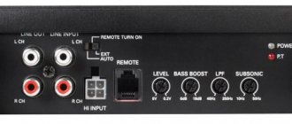
Unique device
Hi-End tube amplifiers are a special class of household appliances. What is this connected with? Firstly, they have some pretty interesting design and architecture. In this model, a person can see everything he needs. This makes the device truly unique. Secondly, the characteristics of a Hi-End tube amplifier differ from alternative models that use transistor integrated circuits. The difference between Hi-End is that a minimum number of parts are used during installation. Also, when evaluating the sound of this device, people trust their ears more than nonlinear distortion measurements and an oscilloscope.
Selecting circuits for assembly
The preamplifier is quite simple to assemble. For it, you can choose any suitable scheme and start assembling. Another case is the output stage, that is, a power amplifier. As a rule, many different questions arise with it. The output stage has several types of assembly and operating modes.
The first type is a single-cycle model, which is considered a standard cascade. When operating in “A” mode, it has slight nonlinear distortion, but, unfortunately, has rather poor efficiency. Also noteworthy is the average power output. If you need to fully sound a fairly large room, you will need to use a push-pull power amplifier. This model can operate in “AB” mode.
In a single-ended circuit, only two parts are enough for the device to work well: a power amplifier and a pre-amplifier. The push-pull model already uses a phase inverted amplifier or driver.
Of course, for two types of output stage, in order to work comfortably with an acoustic system, it is necessary to match the high interelectrode resistance and the low resistance of the device itself. This can be done using a transformer.
If you are a connoisseur of “tube” sound, then you should understand that you need to use a rectifier, which is produced on a kenotron, to achieve such a sound. In this case, semiconductor parts cannot be used.
When developing a Hi-End tube amplifier, you don't have to use complex circuits. If you need to sound a fairly small room, then you can use a simple single-cycle design, which is easier to make and configure.
How I built my own hi-fi amplifier for just $200
Hi all! I wanted to share my experience in finding my sound. Perhaps the experience will be useful to someone, someone will think about how much it costs what we all buy. This option may not be universal, but it is a clear example when the budget can be really very small. After all, for me, the content of equipment is much more important than the manufacturer’s nameplate.
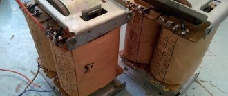
This story began quite a long time ago, I don’t remember exactly when, I think 6-8 years ago. I bought a BBK AV321T receiver at a local “cult goods” store for $140. I purchased it for one sole purpose - to use it as a power amplifier. I read the service manual for it and didn’t even believe that it had such a filling. Never once did it work for me in the environment that the Chinese creator intended - in a home theater. However, for this money I got quite a lot: a toroidal transformer, a good-design power supply with shunted diodes and two 15 tμF capacitors, a classic power amplifier circuit. The declared power is 80 W per channel in stereo, the most real ones. It worked for me as a control amplifier from an external sound card from a PC, then at one time a tube preamp appeared. However, due to life circumstances, he was in demand for only a couple of years and then remained out of work.
Time passed, and I was able to assemble a vinyl player based on the Unitra 602 of the first modification. Quite by accident I was able to buy it for symbolic money in almost its original form - it had been lying on the mezzanine for more than 30 years. Now I began to look for amplification for this player and decided to take the old receiver to a new level and assemble a full-fledged amplifier with a phono stage.
As a result, all that was left of the VVC was a housing and a transformer with power supply and power amplifier boards. Everything else was removed, the thing I didn't like the most was the mirrored front panel :)
"Remains" BBK
If I had to buy all this separately, the amount would be much more than $200.
Even earlier, immediately after purchase, the power supply and power amplifier boards were upgraded. On these boards, the ground and power paths from the power supply to the terminals of the final transistors and from the transistors to the protection relays, and then to the acoustic terminals, which were also replaced, were duplicated with acoustic wire. Additional radiators are installed on the transistors in front of the terminal transistors.
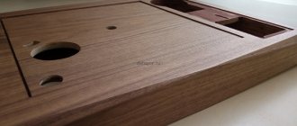
A new front panel was made from artificial stone, I really like this material. The dial-type volume control, input selector and phono preamplifier unit were borrowed from the old Odyssey 010 amplifier.
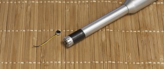
Most of all I had to tinker with the phono stage. A complete revision was carried out, some transistors were replaced. The phono stage is made on two mono boards without a single capacitor. As a result, there is only one capacitor on the signal path from the pickup head to the speaker terminal; I initially installed the domestic K73-17. Of course, it was possible to choose something more interesting and more expensive, but I had used them before, so the result was expected. The signal is routed using a copper microphone cable, good shielding, price only 40r/m. True, I was convinced that this cable was not bad at all; to the ear, it was no worse than the cable that I installed in the player, also copper, inexpensive. Although, again, you can invest in a more expensive option. The result is a full-fledged stereo amplifier in the spirit of minimalism.
I couldn’t resist and installed MKP Jantzen Standard Z-Cap instead of k73-17
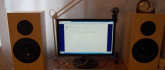
Close-up of volume control and transformer
Now the amplifier in testing mode works specifically with a record player. The sound is reliable, more like a monitor one, perhaps a little lacking in delicacy, all the shortcomings of the recording are brought to the surface, it is difficult to make any complaints about the sound, given its low cost. If I have time, I'll try to compare it with something. But now I just want to listen to vinyl. The amplifier works with homemade two-way speakers. If there is interest, I’ll tell you about this project, but I’m not sure that it will be able to be repeated - a lot of subtleties along this path await those who want to repeat them.
The project can hardly be considered complete; most likely, you will want to replace the capacitors or something else.
Already in the process of writing the article I could not resist and installed the MKP Jantzen Standard Z-Cap instead of the k73-17. The result was immediately audible - the resolution increased, the scene became more prominent.
In general, this is very interesting. And most importantly, all changes made are audible and provide enormous scope for creativity.
In the end, the cost was less than $200, but the result was a very good amplifier. The most worthy thing about it, in my opinion, is the discrete volume control. And the most expensive addition is Jantzen Z-Cap.
I will be happy to answer your questions.
DIY Hi-End tube amplifier
Before starting installation, you need to understand some rules for assembling this type of device. We will need to apply the basic principle of installing lamp devices - minimizing fasteners. What does it mean? You will need to discard the mounting wires. Of course, this cannot be done everywhere, but their number must be minimized.
A good Hi-End tube amplifier uses mounting tabs and strips. They are used as additional points. This type of assembly is called hinged. You will also need to solder the resistors and capacitors that are on the lamp panels. It is highly not recommended to use printed circuit boards and assemble conductors so as to create parallel lines. This will make the assembly look chaotic.
Add a link to a discussion of the article on the forum
RadioKot >Schemes >Audio >Amplifiers >
| Article tags: | Add a tag |
Amplifier with HI-END sound quality
Author: Sergey Kuzmenko Published 04/17/2012 Created with the help of KotoEd.
We present to your attention an amplifier with a very soft sound, like a tube amplifier, but superior to tube amplifiers in other parameters (signal-to-noise ratio and nonlinear distortion).
Reproducible audio range: from 10Hz to 25kHz
Signal-to-noise ratio: no less than 92dB (not weighted)
Harmonic distortion: 0.001%
What pushed me to create such an amplifier was my love for very good and high-quality sound.
After reviewing a lot of various circuits, I made a small sketch of the circuit diagram of the amplifier. Later I came across a search for a good-sounding operational amplifier, and it took about 2 weeks to search for a microcircuit on the Internet at that time.
The first condition is that this operational amplifier must be high-voltage, the second must be of very high quality in terms of signal-to-noise ratio. Before that, I assembled good amplifiers using domestic element base chips K544UD2 and K574UD1, as well as powerful output transistors KT818 and KT819. At that time, their parameters completely suited me.
But with the advent of modern imported equipment on our shelves, the requirements for such an amplifier became much higher; we wanted very high-quality sound, comparable in sound to tube amplifiers.
So, I decided on all the components, the actual assembly of the amplifier itself began, and since at that time I was working in a service center, I did the setup and assembly at work in my free time from repairs.
The first version of the amplifier looked like this - it was just the beginning.
Since at that time I did not yet have either a case or completely wired boards, the device was assembled in a box from DVD player packaging. It worked in this form for about a month, and no incidents occurred during the work. After that, I took up the PCB layout and this is what came out of it.
Well, what do industrial production boards look like:
The amplifier circuitry is quite simple to assemble and does not contain scarce elements. All components can be purchased at any radio market. The classic circuit design of both the input and output stages made it possible to create a very easy-to-assemble amplifier circuit and, importantly, there is no need to configure it. Yes, it does not need adjustment, since the circuit does not contain regulatory elements for adjusting the quiescent currents of the output stage, a thermal stabilization system, etc.
After assembling the amplifier, it is necessary to check the DC voltage at the amplifier output after connecting it to the network; it should be in the range of +20/-20 mV, while the amplifier input must be shorted to ground. If this voltage is within normal limits, the amplifier is ready for operation, just remember to unsolder the jumper at the input. A voltage amplification circuit is assembled on the operational amplifier, with a gain of approximately 25. Transistors VT1, VT2, VT5, VT6, VT7 and VT8 are connected according to the OE circuit and perform the function of current amplifiers with a coefficient of 10. Transistors VT3 and VT4 are used to assemble a thermal stabilization circuit for the circuit itself. amplifier, and they, like the output transistors, are also located on the radiator. If these transistors are not mounted on a radiator, the amplifier will instantly heat up to a temperature of over 90 degrees. The maximum heating temperature of the amplifier under load and long-term operation was 70 degrees. Coil L1 contains from 16 to 20 turns of 1mm PEV-2 wire wound in one layer. It is advisable to use metal-paper capacitors C2 and C7, and multilayer ceramics for the rest. Transistors can be used imported, suitable for the parameters. With certain changes in the circuit, the power of this amplifier can be increased to 100W.
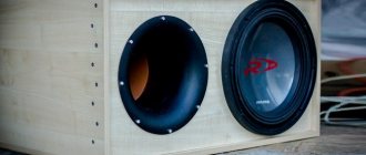
Below is a photo of the assembled amplifier:
Unfortunately, I am not a metal and wood craftsman, but this is what I got out of it. This amplifier has been working quite reliably for 8 years and no problems have occurred. Its sound quality is very decent, in some ways superior to tube amplifiers in terms of softness of sound, not to mention the noise and nonlinear distortions of the tube amplifiers themselves. Yes, yes, I didn’t make a mistake. Comparisons were made in terms of sound quality with such models as NAD, Rotel, Arcam and Yamaha, this amplifier circuit surpassed all of the above models in softness and sound quality. There are two options for boards for the left side and the right side; only the left side of the board layout is in the archive.
Files:
Printed circuit board in SL 5.0 format.
All questions in the Forum.
| What do you think of this article? | Did this device work for you? | |
| 90 | 26 | 28 |
| 3 | 1 |
Removing Interference
Later, you need to eliminate the low-frequency background, if, of course, it is present. Another important point is the choice of grounding point. In this case, you can use one of the options:
- The type of connection is a star, in which all “ground” conductors are connected to one point.
- The second method is to lay a thick copper busbar. It is necessary to solder the corresponding elements onto it.
In general, it is better to find a grounding point yourself. This can be done by determining the level of low-frequency background by ear. To do this, you need to gradually close all the grids of lamps that are located on the ground. If, when the subsequent contact is closed, the low-frequency background level decreases, then you have found a suitable lamp. To achieve the desired result, it is necessary to experimentally eliminate unwanted frequencies. You should also apply the following measures to improve the quality of your build:
- To make filament circuits for radio tubes, you need to use twisted wire.
- Tubes used in the preamplifier must be covered with grounded caps.
- It is also necessary to ground the housings with variable resistors.
If you want to power the preamp tubes, you can use DC current. Unfortunately, this requires connecting an additional unit. The rectifier will violate the standards of a Hi-End tube amplifier, since it is a semiconductor device that we will not use.
Transformers
Another important point is the use of different transformers. As a rule, power and output are used, which must be connected perpendicularly. This way you can reduce the level of low-frequency background. Transformers should be located in grounded enclosures. It must be remembered that the cores of each transformer should also be grounded. There is no need to use shielded wire when installing devices to avoid additional problems. Of course, these are not all the features associated with installation. There are quite a lot of them, and it will not be possible to consider them all. When installing a Hi-End (tube amplifier), you cannot use new element bases. They are now used to connect transistors and integrated circuits. But in our case they will not work.
Resistors
A high-quality Hi-End tube amplifier is a retro device. Of course, the parts for its assembly must be appropriate. Instead of a resistor, a carbon and wire element may be suitable. If you spare no expense in developing this device, you should use precision resistors, which are quite expensive. Otherwise, MLT models are applicable. This is a pretty good element, as evidenced by the reviews.
Hi-End tube amplifiers are also suitable for use with BC resistors. They were made about 65 years ago. Finding such an element is quite simple; you just need to walk around the radio market. If you are using a resistor with a power of more than 4 Watts, you need to choose enameled wire elements.
Capacitors
In a tube amplifier setup, you should use different types of capacitors for the system itself and the power supply. They are usually used to adjust the tone. If you want to get high-quality and natural sound, you should use a coupling capacitor. In this case, a small leakage current appears, which allows you to change the operating point of the lamp.
This type of capacitor is connected to the anode circuit, through which a large voltage flows. In this case, it is necessary to connect a capacitor that maintains a voltage greater than 350 volts. If you want to use quality parts, you need to use parts from Jensen. They differ from analogues in that their price exceeds 3,000 rubles, and the price of the highest quality radio elements reaches 10,000 rubles. If you use domestic elements, it is better to choose between the K73-16 and K40U-9 models.
Make a transformer for a tube amplifier at home
Making a good output transformer at home is quite difficult, but purchasing or ordering one made according to all the rules is not cheap. Recently, there have been proposals to use standard unified transformers such as TAN or TN as output for lamp ultrasonic units. And although in this case you should not count on getting the maximum possible parameters, this option deserves attention due to its accessibility and practicality.
Currently, tube amplifiers used by musicians and released more than 30 years ago still exist. This equipment, as a rule, is “raced” until it is completely worn out. Many years of experience in its operation testify to the reliability of tube amplifiers. Many copies produced, for example, by such companies as BEAG, TESLA, MARC HAL and others, are well preserved. Their repair was most often limited to replacing lamps and electrolytic capacitors.
In more complex cases, it was necessary to replace elements on which the parameters of the amplifiers could depend. Some elements, such as resistors, were destroyed if they malfunctioned. However, it was impossible to determine their denomination from the inscription. It was selected experimentally, as long as the tube amplifier would work, since not all owners and repairmen had circuit diagrams of the equipment.
For these reasons, as well as due to the increased interest in tube circuitry, readers may be interested in the circuits of the most popular pop amplifiers at the end of the last century. These circuits can serve as classic examples of high-quality tube ultrasonic frequencies, which, together with good acoustics, provide the sound quality for which many audiophiles and musicians feel nostalgic.
Assembly
Let's start the assembly with the pre-amplifier. Its installation follows a fairly simple scheme. It is also necessary to provide power control and a separator for tone control. It should be tuned to low and high frequencies. To increase shelf life, you need to use a multi-band equalizer.
In the laughter of the preamplifier you can see similarities with the common 6N3P double triode. The element we need can be assembled in a similar way, but use the final cascade. This is also repeated in stereo. Remember that the structure must be assembled on a circuit board. First it needs to be debugged, and then it can be installed on the chassis. If you installed everything correctly, the device should turn on immediately. Next you should move on to configuration. The value of the anode voltage for different types of lamps will differ, so you will need to select it yourself.
Input switching block.
This board contains the input and output connectors of the preamplifier, as well as relays for switching them:
The preamplifier has four line inputs, both balanced and conventional unbalanced. balanced are preferable , as they provide less noise and are less susceptible to interference. To use unbalanced inputs, jumpers JP1…JP4 must be installed.
Phono preamplifiers are connected to input No. 4. If you do not use them, then there is simply no need to connect connector K13. Note that phono preamplifiers have an unbalanced output.
This part is also assembled on a separate printed circuit board:
Click to enlarge
List of elements of the input switching block:
Resistors: R1,R2=0 Ohm
Capacitors: C1…C4 = 220 n/100 V, 10%
Miscellaneous: K1,K3,K5,K7 = 3-pin balanced (XLR) female K11 = 3-pin balanced, male K2,K4,K6,K8…K10,K12 = Clip jacks K13,JP1…JP4 = two-pin male connector with 0.1'' pitch K14,K15,K16 = four-pin male connector with 0.1'' pitch K17 = ten-pin (2×5) connector with RM 0.1'' pitch S1…S4 = three-pin male connector with 0.1'' steps RE1…RE4 = 12 V/960 Ohm relay with 2 contact groups
Components
If you do not want to use a high-quality capacitor, then you can use K73-16. It will be suitable if the operating voltage is more than 350 volts. But the sound quality will be noticeably worse. Electrolytic capacitors are also suitable for this voltage. You need to connect the C1-65 oscilloscope to the amplifier and submit a signal that will pass from the audio frequency generator. During the initial connection, you need to set the input signal to about 10 mV. If you need to know the gain, you will need to use the output voltage. To select the average ratio between low and high frequencies, it is necessary to select the capacitance of the capacitor.
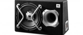
You can see a photo of a Hi-End tube amplifier below. For this model, 2 lamps with an octal base were used. A double triode is connected to the input, which is connected in parallel. The final stage for this model is assembled on a 6P13S beam tetrode. This element has a built-in triode, which allows you to get good sound.
To configure and check the functionality of the assembled device, you must use a multimeter. If you want to get more accurate values, you should use a sound generator with an oscilloscope. When you have taken the appropriate devices, you can proceed to setup. At cathode L1 we indicate a voltage of about 1.4 Volts; this can be done if you use resistor R3. The output lamp current must be specified as 60 mA. To make resistor R8, you need to install a pair of MLT-2 resistors in parallel. You can use other resistors of different types. It should be noted that a rather important component is the isolation capacitor C3. It was not in vain that it was mentioned, since this capacitor has a strong influence on the sound of the device. Therefore, it is better to use a proprietary radio element. Other elements C5 and C6 are film capacitors. They allow you to increase the quality of transmission of various frequencies.
A power supply built on the 5Ts3S kenotron is worth finding. It complies with all the rules for constructing the device. A homemade Hi-End tube power amplifier will have high-quality sound if you find this element. Of course, otherwise it is worth looking for an alternative. In this case you can use 2 diodes.
For a Hi-End tube amplifier, you can use the appropriate transformer, which was used in old tube technology.
Display block.
As one would expect, Douglas Self considered most common display systems, both with large displays and LEDs, to be uninformative and developed his own system, which quite simply (using just one LED), but clearly (according to Douglas) shows the amplifier signal level .
The diagram of the indication block is shown in the figure:
Click to enlarge
rectifier is made on elements IC1A with R1, R2, D1 and D2 , the cascade on IC1B is a precision detector of the peak value to which capacitor C2 is charged. From it, the voltage through the buffer stage on IC2A is supplied to the logarithmic converter IC2B.
For low-level signals, the gain of this stage is determined by the values of resistors R6 and R7. When the signal level increases, diode D5 opens, and resistor R8 is connected in parallel with resistor R7, due to which the gain of the cascade on IC2B decreases. With a further increase in the signal level, similarly, resistor R9 is connected through diode D6. Such a simple implementation of this node slightly inaccurately repeats the logarithmic dependence, but is quite sufficient for indication.
The signal then goes to comparator IC5A. The response threshold is set by resistors R21 and R22. Since the output of IC5A provides a negative level, an inverter on IC5B is introduced into the circuit. The LED is connected to connector K6. Both stereo channels are combined at the inverter input, due to which one LED provides information about the stereo signal. At normal signal level, the LED should light approximately half the time.
The display unit can be connected to the linear input of the amplifier or to the outputs of phono preamplifiers. Relay contact groups RE1B and RE1C are used for this purpose. The indicator can also be turned off using contact groups RE2B, RE2C.
The circuit is mounted on a separate printed circuit board:
The location of the elements is shown in the figure:
Click to enlarge
List of display block elements:
Resistors: (0.25 W; 1%) R1…R3,R5,R11…R13,R15 = 20 k R4,R6,R7,R14,R16,R17 = 10 k R8,R9,R18,R19 = 1 k R10 ,R20 = 100 k R21 = 910 Ohm R22,R23,R25 = 22 k R24= 100 Ohm R26,R27 = 220 Ohm
Capacitors: C1…C4 = 2.2 µF/100 V, 20% C5…C9 = 100 nF/100 V, 10%, C10,C11 = 100 µF/25 V, 20% C12,C13 = 220 nF/100 V , 10 %,
Inductances: L1,L2 = 1 mH, 370 mA
Active elements: D1…D14 = 1N4148 T1 =BC557B IC1…IC4 = NE5532 IC5 = LM339
Miscellaneous: K1…K4,K6 = 2-pin connector with 0.1'' pitch K5 = 3-pin connector with 0.1'' pitch K7 = 3-pin screw connector with 0.5 mm pitch RE1,RE2 = relay, 12 V/960 Ohm, 2 groups of contacts.