What are the most common faults?
The most common problem that arises when using beech is, of course, the power connector. If we hold the wire with our hand while jumping from the bed to the table and back, then usually everything is fine. But how many people do this? I took the car and went, but the laptop’s power supply was dragging behind, creating a considerable load on the connector.
In this situation, most often it is not the power supply plug that suffers, but the laptop socket. But replacing the socket is not the topic of the article, and therefore we will not consider it.
It is equally rare for the power supply wire to break. Usually a day off, since the network is as thick as a pencil and hard as a wire, it is difficult to break. The output can break both near the plug and near the power supply itself.
The power supply units themselves fail much less often, but this also happens. Overvoltage, overload, shock, banal marriage - everything happens. It even happens: I turned off a perfectly good laptop in the evening, and in the morning it starts on battery power, because for some reason the power supply does not work.
Output Rectifier: The Most Popular Device
Rule #6: The signal coming from the UPS output is rectified and smoothed.
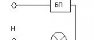
The simplest rectifier circuit, consisting of a diode and a storage capacitor, is shown in the picture below.
It can be modified by connecting additional capacitors, chokes, and filter elements.
How to replace a plug or repair a damaged wire
Let's start with the simplest thing - repairing a broken laptop power cable. We cut the wire at the point of damage and strip both ends.
Healthy! If the wire breaks right under the plug (or power supply), then you will have to slightly modify the plug itself or the power supply bushing. Take a mounting knife or a simple safety razor blade and cut off part of the plug (sleeve).
We put two heat-shrinkable tubes of different diameters on the wire. It is more convenient, reliable and aesthetically pleasing than electrical tape.
Now we arm ourselves with a soldering iron, carefully service the cleaned areas and solder the central wires. We slide thin heat shrink over the soldering area.
We heat the pipe with matches so that it “sits down.” We solder the screens, being careful not to burn out the insulation of the central core. To do this, you can put a piece of electrical cardboard on the central core at the soldering point.
We stretch the second tube, seat it with a gas torch or lighter, and the job is done.
If there are no heat-shrinkable tubes of the required diameter, then regular insulating tape will do. It will not be as aesthetically pleasing, but quite reliable.
Now briefly about repairing and replacing the plug. Such an operation may be necessary if the factory soldering is poor, if the wire is broken very deep in the connector shell, or if we want aesthetics.
We cut off the wire at the fracture site or above. Using a mounting knife, cut the shell along its entire length. We turn it inside out, shake out the insides, unsolder the wires from the plug (if they have not already fallen off due to poor soldering) and we get the following:
"Disassembled" non-separable connector
We strip the cut wire, tin it, solder the central core, and carefully insulate it. Solder the screen.
Soldering is completed, assembly remains
We take the cut shell, cut it from the inside so that it can be installed in place and the ends meet at the cut site. We put heat shrink with a diameter of 10 mm on the shell and shrink it by heating it over the burner of a gas stove. For the front part of the connector we take a heat-shrink tube with a diameter of 13 mm. Put it on, seat it and you're done.
As for a complete replacement, everything is obvious. All new plugs are removable. We cut off the old one, solder the new one, not forgetting to put a sheath on the wire before soldering. We soldered it, clamped the cable with a special crimping tab (marked with an arrow in the photo below), pushed the sheath over the soldering area and that’s it.
New plugs are always removable
We seem to have sorted out the wires and connectors. Now let's move on directly to repairing laptop power supplies. I would like to immediately warn you that to carry out repairs you must have at least minimal knowledge of radio engineering, be able to hold a soldering iron in your hands and use measuring instruments. If all this is available, then you can start.
How to open the PSU case
Before you start repairing a laptop charger, you need to disassemble it, since almost all power supplies for beeches are non-separable. Nevertheless, you can disassemble the power supply without much difficulty. Let's consider two options.
Disassembly option 1
We arm ourselves with a regular medical syringe and fill it with gasoline. We carefully pour the BP seam around the entire perimeter. We wait 5-10 minutes and repeat the operation.
Now take a flat blade screwdriver and freely separate the parts of the housing. If it doesn’t work, repeat the procedure.
Disassembly option 2
Unfortunately, gasoline does not always help - everything will depend on the material of the housing and the method of its connection. If, for example, it is welded, then gasoline will not help. In this case, we arm ourselves with a knife and a hammer. We place a knife on the seam and, lightly tapping it with a hammer, we go around the perimeter.
Using the same knife, we separate the parts of the body.
Expert opinion
Alexey Bartosh
Specialist in repair and maintenance of electrical equipment and industrial electronics.
Ask a Question
Important! We knock carefully with a hammer, controlling the force, so as not to cut through the case and damage the power supply itself. Don't try to do everything quickly and the first time. If after one pass it is not possible to separate the halves of the body, it is better to go through it with a knife and hammer again.
Voltage conversion circuit
Now let's look at how power voltage conversion occurs on the Wistron Janus platform. As we have already found out, most control voltages for converters are generated from the DCBATOUT signal. They are fed to various DC/DC converters to obtain lower voltages.
Voltage conversion circuit in the Wistron platform
So, the BQ24717 charger (labeling HPA02224RGRR) generates the DCBATOUT voltage, which is supplied to other converters. The main one is TPS51125, which generates the standby power supply of the S5 mode - 3.3 and 5 V (5V_S5 and 3D3V_S5), as well as 15V_S5, 3D3V_AUX_S5 and 5V_AUX_S5. Also, to enable Wake-on-LAN, the Ethernet controller is powered through the AO3403 converter, which generates the +3.3V 3D3V_LAN_S5 signal.
The TPS51216 converter is involved in generating the 1D35V_S3 voltage in S3 mode. All other pulse converters (marked with a dashed line) generate voltages for mode S0: 2 TPS22966 and SIRA06DP microcircuits for the video card, PWM controller ISL95813 and RT8237 for the processor, AP3211 for powering the video card core.
Power supply for peripheral devices and controllers in S0 mode is provided by AP2182SG, AP2301M8G microcircuits (5V for USB); TPS22966 and SY6288 (5V for drives). The screen matrix is powered by a voltage of 3.3 V (LCDVDD), coming along a chain from the standby voltage in S0 mode through the RT9724 microcircuit.
Separately, I would like to say about the linear power regulator (LDO) TLV70215, which generates 1.5 V from 3.3 V for the processor.
Typical laptop power supply circuits
Before we start repairing, let’s understand the principle of operation of the power supply of beeches. To do this, consider a couple of typical power supply circuits for laptops. Let's start with something simpler.
The numbers in the diagram indicate the nodes:
- 1 – block of input filters and rectifier;
- 2 – generator with PWM and power switch;
- 3 – pulse transformer;
- 4 – low-voltage rectifier;
- 5 – output voltage stabilization circuit.
The mains voltage, having passed through the mains filter, is rectified by the diode bridge, smoothed out and supplied to the pulse transformer. A master oscillator equipped with a powerful field-effect transistor switch controls the flow of current through the transformer. The voltage reduced by the transformer is rectified by a low-voltage rectifier and supplied to the load through an inductive filter.
Stabilization of the output voltage is carried out using feedback - the voltage from the additional winding is supplied to the optocoupler of the stabilization unit, and it, in turn, controls the operation of the PWM unit of the master oscillator, changing the duty cycle of the transformer control pulses.
The next scheme is more complex, has better characteristics than the previous one, but the operating principle is almost the same:
The numbers in the diagram indicate the nodes:
- 1 – block of input filters and rectifier;
- 2 – generator with PWM;
- 3 – temperature protection;
- 4 – pulse transformer;
- 5 – power switch on a field-effect transistor;
- 6 – low-voltage rectifier;
- 7 – output voltage stabilization circuit.
The mains voltage is filtered and rectified, then supplied to a pulse transformer, which is controlled by a PWM generator using an external power switch. The pulse voltage reduced by the transformer is rectified and supplied to the load. The stabilization unit through an optocoupler provides feedback for stabilizing the output voltage. The temperature protection unit will turn off the power supply if the temperature of its components (in particular, the power switch) becomes too high.
I think we can stop here, since all power supplies for laptops have the same structural diagram and operate on the same principle of pulse conversion. The differences are only in the circuitry. A complex knot has the best characteristics, a simple one has the worst. But they all perform the same functions. So, having understood how the power supplies, the circuits of which we have examined, work, it is not difficult to understand any other.
Important! It is, of course, difficult to understand completely, but it will be possible to identify the nodes that we have disassembled without difficulty. And this is the main thing, since these are the nodes that most often fail.
ISL6251 charger operation and battery charge.
+19V power is supplied to pin 24 of the DCIN charger microcircuit from the power connector through the PD16 diode and PR281 resistor. If you replaced the microcircuit, check if the resistor is intact. Inside the microcircuit, at pin 1 VDD, a supply voltage of +5V is formed, which is then supplied via PR86 to pin 15 VDDP and powers the remaining nodes of the microcircuit. We check the presence of +5V on pin 15.
The VREF pin should have a reference voltage of 2.39v generated by the charger
ACSET input - the charger detects a 19V supply voltage, which the divider on PR280 and PR282 reduces by 14 times. To do this, the voltage at ACSET must exceed 1.26V, which corresponds to 18.0V at the input. Having detected normal power, the charger lowers ACPRN to a low level and sends a signal to the multicontroller.
The multicontroller communicates with the battery controller and, if charging is necessary, sets a high level at the EN pin of the charger, allowing it to charge.
At the CELLS pin, the multicontroller sets a voltage depending on the number of cells in the battery, thereby indicating to the charger what voltage to supply to the battery.
The CSIN CSIP pins are connected to the power supply current sensor - resistor PR61, and the CSON CSOP pins are connected to the charge current source. If the current exceeds, the charger stops charging the battery.
Thus, to charge the battery, it is necessary that the charger be powered (DCIN = 19v, VDD and VDDP = 5v, VREF = 2.39v), so that it detects power (ACSET >1.26v) and the multicontroller gives it the EN signal.
Generation should start on transistors PQ55 PQ57, the currents on PR61 and PR78 should not exceed the maximum permissible values. It should be noted here that in addition to the PR61 PR78 resistors themselves, PR74 PR76 PR72 PR73 may also burn out, which is why the charger may not measure currents correctly.
