Light music on AN6884 - from simple to complex
In this article I will talk about the use of the popular AN6884 microcircuit. We will start with a simple indicator with 5 LEDs, which can be easily assembled by any beginning radio amateur, and we will end with a huge 7-band spectrum analyzer for those who have already tried their hand at simple circuits and want something more.
Line of 5 LEDs
The microcircuit in question allows you to control a scale of 5 LEDs, displaying the audio signal level on it. The signal does not have to be audio. But since the scale in this chip is logarithmic, it is perfect for indicating sound level.
In the datasheet, the authors offer us the following circuit for connecting the AN6884 chip:
The Vcc supply voltage can be supplied over a very wide range - from 3 to 16 volts. In our experiments we will limit ourselves to 9 volts from the Krona. Only the value of resistance R, which limits the current through the LEDs, depends on the supply voltage.
The resistor and capacitor connected to the 7th leg play the role of a timing RC circuit. By changing the resistor value, you can change the decay rate of the LED line. If instead of 10 kOhm you put 2...3 kOhm, the column will move faster. If you replace it with 30 kOhm, the column will move much slower. The optimal value, in my opinion, is 8...10 kOhm.
The circuit can be slightly altered (Fig. 3). Instead of one common resistor R, put five separate ones for each LED. This way you can make the brightness of the LEDs more uniform. If you use LEDs of different colors, you can select suitable resistors for each type of LED. It often happens that green and blue LEDs, at the same current, burn brighter than red and yellow ones.
At the input of the circuit there is a standard 3.5mm audio jack. Its common wire is connected to the common wire of the circuit, and one of the channels (left or right) is connected to the input circuit. Important: if you want to take a signal from the left and right channels at the same time, under no circumstances should they be short-circuited. How to remove a signal from two channels at once will be discussed below.
Demonstration of the circuit operation:
Adding a preamplifier
At first glance, the scheme works well. However, there are several problems. The player has to be cranked up to almost maximum volume in order for the line of diodes to light up completely. And besides, the indicator displays the overall volume of the music, rather than flashing in time with the rhythm. As a result, the indicator does not look very dynamic.
How to fix it? We will install a pre-amplifier and a low-pass filter. We will make them using operational amplifiers. Let's take the RC4558 chip. It comes in a DIP-8 package and has two independent operational amplifiers inside - just what we need.
Block diagram of RC4558:
Circuit with amplifier and mixing channel:
Through resistors R8, R9 and variable resistor R10, the signals of the left and right channels are mixed. Operational amplifier DA2 works as a pre-amplifier that increases the input signal level to the required level. The gain of the operational amplifier in such a connection is determined by the formula 1 + R13 / R12. In our amplifier it will be 1 + 200 / 10 = 21. This gain is quite enough to light all 5 LEDs even at low input volume. If the sound level is too high (all LEDs will light continuously), it can always be adjusted with variable resistor R7.
Most audio op-amp circuits use a bipolar supply: there is ground (zero potential), a positive voltage of +U and a negative voltage of the same value -U. This is useful for enhancing audio signal processing, since audio is a signal of alternating polarity.
But we only have one 9-volt battery at our disposal. Connecting two batteries or a special power supply would be completely irrational. Therefore, we will create an artificial “midpoint” - a point whose potential relative to the ground will be equal to half the supply voltage. In these diagrams it is indicated in the form of a triangle. The middle point in Fig. 6 is created by a voltage divider, resistors R15 and R16 and capacitor C4. The lower the value of resistors R15 and R16, the more stable the potential at the midpoint, but the greater the current flowing through the resistors. In our case, 1…2 kOhm resistors will be sufficient.
Filtering low frequencies
Now you can use the second operational amplifier in the RC4558 and make a low-pass filter on it.
A low-pass filter with an upper transmission limit of about 80 Hz is assembled using resistor R14 and capacitor C4. This frequency is called the cutoff frequency and is determined by the formula 1/(2*Pi*R14*C4). All sound components below 80 Hertz pass through the filter virtually unchanged, while higher frequencies are significantly attenuated. Moreover, the higher the frequency, the stronger the attenuation. The DA2.2 operational amplifier serves as a repeater. It “repeats” at its output the signal that arrives at its input. This is done so that the elements located after the low-pass filter (these are C6, R7, DA1) do not affect the filter’s passband.
Now with a low-pass filter, the circuit works much more interesting and effective. The columns jump clearly in time with the rhythm. You can verify this by comparing the new video with the previous one. At the end of the video there is a demonstration of working in the dark. Do not miss!
Expanding indicators
You can move on and build something more complex and impressive. For example, an indicator consisting not of 5, but of 10 LEDs. There are two ways to do this by combining two AN6884 chips.
First way. Let's combine the two indicators so that the LEDs connected to one and the other AN6884 alternate. In Fig. 9, all odd LEDs are connected to DA1, and all even LEDs are connected to DA2.
Let's say we connect the inputs (8th inputs) and send the same signal to them. In this case, the microcircuits will work absolutely synchronously and the LEDs will turn on in pairs (HL1-HL2, HL3-HL4, etc.)
We need them to light up in turn - HL1, HL2, HL3, HL4, etc. To do this, we use resistors R14 and R15 to slightly attenuate the signal level at the input of one of the microcircuits - DA1. By fine-tuning resistor R14, we ensure that LED HL2 lights up after HL1, HL4 lights up after HL3. After adjustment, we no longer need to touch resistor R14. Next, we set the common input level for the two microcircuits with variable resistor R13.
The resulting indicator more accurately displays the sound level than an indicator with 5 LEDs. Important conditions: the values of resistors R11 and R12 and capacitors C1 and C2 must be equal so that the columns rise and fall at the same speed.
Second way. Let's put two scales “on top of each other”. LEDs 1 to 5 are connected to the DA1 chip, LEDs 6 to 10 are connected to DA2.
The input of the DA2 microcircuit must be supplied with a signal that is greatly weakened compared to the signal at the DA1 input. This attenuation, as in the previous case, is set by resistors R14 and R15. By adjusting resistor R15, a mode is selected in which the HL6 LED lights up immediately after the HL5 LED.
Such an indicator will display the volume level over a wider range than previous versions.
Building a spectrum analyzer
By further developing these circuits, you can assemble even more interesting devices. For example, a multichannel spectrum analyzer is a light-music device with jumping light columns, where each column corresponds to a specific frequency band - from low to high.
To do this, you will need to place several indicators and connect the signal to them through bandpass filters tuned to different frequencies. To the output of the operational amplifier DA2.1 in Fig. 8, instead of the low-pass filter on R14, C4, DA2.2, several bandpass filters of this type should be connected in parallel:
An indicator on two AN6884s is connected to the output of each filter. The table shows the values of capacitances and resistances for different bands of a 7-band spectrum analyzer. The values were calculated using the Filter Wiz Pro program.
| Center frequency | 100 Hz | 200 Hz | 500 Hz | 1 kHz | 2 kHz | 5 kHz | 10 kHz |
| The width of the line | 10 Hz | 20 Hz | 50 Hz | 100 Hz | 200 Hz | 500 Hz | 1 kHz |
| Ra | 390 Ohm | 75 Ohm | 91 Ohm | 240 Ohm | 72 Ohm | 51 Ohm | 24 ohm |
| Rb | 100 kOhm | 82 kOhm | 100 kOhm | 100 kOhm | 82 kOhm | 91 kOhm | 91 kOhm |
| Ca | 330 nF | 100 nF | 33 nF | 33 nF | 10 nF | 4.7 nF | 330 nF |
| Cb | 330 nF | 1 µF | 330 nF | 33 nF | 100 nF | 47 nF | 330 nF |
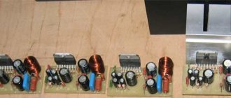
I assembled exactly this circuit four years ago, when I was still learning electronics. The photo shows the result of the work. For size comparison: side by side is a 17-inch monitor.
And, of course, a video of this device in action:
And in conclusion
Today, if I were to make a similar spectrum analyzer again, I would, of course, make it on microcontrollers with an ADC and fast Fourier transform. It would have been much simpler and cheaper. But for beginning radio amateurs it will be very interesting and useful to try their hand at analog circuits like this one. I wish all those who are just starting their journey in electronics good luck in this difficult but exciting business!
Warning: Be careful when experimenting with light and music devices when connecting your iPhones and iPods to them. This especially applies to development boards, where the device has not yet been debugged and there may be errors. It’s better to take an old unnecessary cassette player or a Chinese player for 300 rubles for the experiment. Once upon a time, out of inexperience, I burned an MP3 player, accidentally releasing 16 volts from the circuit to its output. Be careful!
I would be very grateful for constructive criticism.
List of radioelements
| Designation | Type | Denomination | Quantity | Note | Shop | My notepad |
| Scheme 1 | ||||||
| DA1 | Chip | AN6884 | 1 | Search in the Otron store | To notepad | |
| C1 | Electrolytic capacitor | 2.2 µF | 1 | Search in the Otron store | To notepad | |
| C2 | Electrolytic capacitor | 10 µF | 1 | Search in the Otron store | To notepad | |
| R1-R5 | Resistor | 1 kOhm | 5 | Search in the Otron store | To notepad | |
| R6 | Resistor | 10 kOhm | 1 | Search in the Otron store | To notepad | |
| R7 | Variable resistor | 10 kOhm | 1 | Search in the Otron store | To notepad | |
| HL1-HL5 | Light-emitting diode | 5 | Search in the Otron store | To notepad | ||
| Scheme 2 | ||||||
| DA1 | Chip | AN6884 | 1 | Search in the Otron store | To notepad | |
| DA2 | Operational amplifier | RC4558 | 1 | Search in the Otron store | To notepad | |
| C4, C7 | Electrolytic capacitor | 10 µF | 2 | Search in the Otron store | To notepad | |
| C6 | Electrolytic capacitor | 2.2 µF | 1 | Search in the Otron store | To notepad | |
| C8 | Capacitor | 1 µF | 1 | Search in the Otron store | To notepad | |
| R1-R5 | Resistor | 1 kOhm | 5 | Search in the Otron store | To notepad | |
| R6, R8, R9, R12 | Resistor | 10 kOhm | 4 | Search in the Otron store | To notepad | |
| R7, R10 | Variable resistor | 10 kOhm | 2 | Search in the Otron store | To notepad | |
| R11 | Resistor | 100 kOhm | 1 | Search in the Otron store | To notepad | |
| R13 | Resistor | 200 kOhm | 1 | Search in the Otron store | To notepad | |
| R15, R16 | Resistor | 2 kOhm | 2 | Search in the Otron store | To notepad | |
| HL1-HL5 | Light-emitting diode | 5 | Search in the Otron store | To notepad | ||
| Scheme 3 | ||||||
| DA1 | Chip | AN6884 | 1 | Search in the Otron store | To notepad | |
| DA2 | Operational amplifier | RC4558 | 1 | Search in the Otron store | To notepad | |
| C3 | Capacitor | 1 µF | 1 | Search in the Otron store | To notepad | |
| C4 | Capacitor | 0.22 µF | 1 | Search in the Otron store | To notepad | |
| C5, C7 | Electrolytic capacitor | 10 µF | 2 | Search in the Otron store | To notepad | |
| C6 | Electrolytic capacitor | 2.2 µF | 1 | Search in the Otron store | To notepad | |
| R1-R5 | Resistor | 1 kOhm | 5 | Search in the Otron store | To notepad | |
| R6, R8, R9, R12, R14 | Resistor | 10 kOhm | 5 | Search in the Otron store | To notepad | |
| R7, R10 | Variable resistor | 10 kOhm | 2 | Search in the Otron store | To notepad | |
| R11 | Resistor | 100 kOhm | 1 | Search in the Otron store | To notepad | |
| R13 | Resistor | 200 kOhm | 1 | Search in the Otron store | To notepad | |
| R15, R16 | Resistor | 2 kOhm | 2 | Search in the Otron store | To notepad | |
| HL1-HL5 | Light-emitting diode | 5 | Search in the Otron store | To notepad | ||
| Scheme 4 | ||||||
| DA1, DA2 | Chip | AN6884 | 2 | Search in the Otron store | To notepad | |
| C1, C2 | Electrolytic capacitor | 10 µF | 2 | Search in the Otron store | To notepad | |
| C3 | Electrolytic capacitor | 2.2 µF | 1 | Search in the Otron store | To notepad | |
| R1-R10 | Resistor | 1 kOhm | 10 | Search in the Otron store | To notepad | |
| R11, R12 | Resistor | 10 kOhm | 2 | Search in the Otron store | To notepad | |
| R13 | Variable resistor | 1 kOhm | 1 | Search in the Otron store | To notepad | |
| R14 | Variable resistor | 10 kOhm | 1 | Search in the Otron store | To notepad | |
| R15 | Resistor | 20 kOhm | 1 | Search in the Otron store | To notepad | |
| HL1-HL10 | Light-emitting diode | 10 | Search in the Otron store | To notepad | ||
| Scheme 5 | ||||||
| DA1, DA2 | Chip | AN6884 | 2 | Search in the Otron store | To notepad | |
| C1, C21 | Electrolytic capacitor | 10 µF | 2 | Search in the Otron store | To notepad | |
| C3 | Electrolytic capacitor | 2.2 µF | 1 | Search in the Otron store | To notepad | |
| R1-R10 | Resistor | 1 kOhm | 10 | Search in the Otron store | To notepad | |
| R11, R12 | Resistor | 10 kOhm | 2 | Search in the Otron store | To notepad | |
| R13 | Variable resistor | 1 kOhm | 1 | Search in the Otron store | To notepad | |
| R14 | Resistor | 20 kOhm | 1 | Search in the Otron store | To notepad | |
| R15 | Variable resistor | 10 kOhm | 1 | Search in the Otron store | To notepad | |
| HL1-HL10 | Light-emitting diode | 10 | Search in the Otron store | To notepad | ||
| Add all | ||||||
Tags:
- Spectrum analyzer
- Light-emitting diode
Schematic diagram
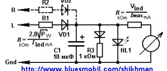
A more affordable chip, the AN6884 LED level indicator, does not have any comparators for supplying external voltage to the reference voltage divider.
Therefore, it is not possible to adjust its sensitivity - it is always about 250-300 mV on the full scale. This makes it somewhat difficult to use the AN6884 as an LED car battery voltage indicator.
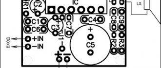
Rice. 1. Schematic diagram of the LED car battery voltage indicator on AN6884.
Microcircuit A1 - AN6884, is designed to work in signal level indicators in audio equipment. The microcircuit is designed to be powered from a source of 5...15.5V, this corresponds to the voltages that can be in low-voltage circuits of a car. The meter circuit is powered by the same source whose voltage it measures.
The fact that the supply voltage changes simultaneously with the measured voltage does not affect the reliability of the measurement. The comparators on the AN6884 chip compare the input voltage with a reference voltage obtained from the chip's internal voltage regulator. Therefore, the supply voltage only affects the brightness of the indicator LEDs, but not the measurement accuracy.
The minimum voltage that the device can measure is 9V. At this voltage, HL5 lights up. The HL1 LED lights up when the voltage is more than 14.5V.
Rice. 2. Printed circuit board for the indicator circuit.
In order for the indication to start at 9V, there is a circuit VD1-R2 in the circuit. And the voltage at the input of the microcircuit is removed from R2. Therefore, as long as the voltage between the lower terminal of R2 and the cathode of VD1 is less than 7.5V, the resistance of VD1 is high and the voltage across R2 is very small.
When the stabilization voltage of the zener diode exceeds, it begins to pass current, and with a further increase in voltage, the voltage on R2 will increase proportionally.