For a digital signal, the coordinates along the horizontal axis are located at regular intervals, in accordance with the sampling frequency. In the common Audio-CD format this is 44100 points per second. The vertical accuracy of the coordinate height corresponds to the bit depth of the digital signal; for 8 bits it is 256 levels, for 16 bits = 65536 and for 24 bits = 16777216 levels. The higher the bit depth (number of levels), the closer the vertical coordinates are to the original wave.
Analogue sources are: vinyl and audio cassettes. Digital sources are: CD-Audio, DVD-Audio, SA-CD (DSD) and files in WAVE and DSD formats (including derivatives of APE, Flac, Mp3, Ogg, etc.).
Sound - what is it?
Sound is a physical phenomenon. These are elastic waves of mechanical vibrations propagating in a gaseous, solid or liquid medium. Sound is often considered to be those vibrations that are perceived by animals and people. The main characteristics of sound are amplitude and frequency spectrum. For people, the second indicator ranges from 16-20Hz – 15-20 kHz. Everything below this range is called infrasound, above - ultrasound (up to 1 GHz) or hypersound (from 1 GHz). The loudness of the sound determines the sound pressure and its effectiveness, the shape of the vibrations and their frequency, but the pitch of the sound depends on the magnitude of the sound pressure and frequency.
Analog to digital conversion
The audio signal can be analog or digital. If we consider an analog signal emanating from analog equipment, it is a continuous electrical signal. Digital sound is a signal represented by discrete numerical values of its amplitude. That is, such a signal is recorded in the form of numbers, and it is read by computer technology.
Analog audio can be converted to digital by processing the analog signal, giving it numerical values. This can be done in two stages. The first is sampling, during which values are selected from the signal to be converted at certain time intervals according to given values. The second is quantization: the process of breaking down values obtained by sampling sound amplitude values as closely as possible.
In analog-to-digital conversion, exact values are not used - all values are indicated rounded, since due to limitations in the RAM of the devices, it is impossible to indicate the real amplitude value - it is infinite.
1.4. Oversampling
The essence of this technique is to use higher, usually four times higher, sampling rates. Thus, if the original sampling frequency is 44.1 KHz, then the signal will be digitized at a frequency of 176.4 KHz (44.1 × 4), which allows frequencies up to 88.2 KHz to be present in the signal, which, in turn, eliminates the problem of using analog filters with realistic slopes attenuation. Subsequently, the already digitized signal, containing information in the frequency range from direct current (0 Hz) to 88.2 KHz (half the sampling frequency), is digitally filtered in order to exclude frequencies above 20 KHz from the signal. Lastly, the sampling frequency of the already digitized and filtered signal is reduced, or, more simply, every three amplitude measurements (samples) out of four are discarded. The general operating principle of this technique is shown in Diagram 4.
It should be noted that the higher the sampling rate, the more detailed the analog signal will be represented. Theoretically, on a continuous straight line (analog signal) you can put an infinite number of points that will describe it. Thus, the more such points there are, the more detailed it will be possible to describe the original signal. However, in addition to the frequency itself, the stability or constancy of the readings plays an important role.
Sampling frequency and bit depth
These two concepts are often discussed when describing digital recording devices. So, the sampling rate means the frequency at which the recording device samples the frequency of input signals. When analog audio is converted to digital, it is recorded as individual samples, that is, signal intensity values at specific time periods.
The sampling frequency most often has the following standard values:
- 44.1 kHz;
- 48 kHz;
- 96 kHz.
To obtain the best quality digital recording, you should use a higher sampling rate: due to the greater number of samples per second of time, the quality of the converted sound improves.
What is bit depth? When it comes to recording devices, we often hear units of information such as 16 bits, 24 bits, etc. They denote the number of units of information that can be used to represent the value of samples obtained during digital recording (and each sample separately). In this case, the higher the unit of measurement, the higher the quality of the resulting sound. However, it is worth considering that the value of sound intensity does not depend on the number of bits, but on the accuracy of its representation.
Audio. Digital and analogue audio
Despite the fact that we assimilate most external information through vision, sound images are no less important for us, and often even more so. Try watching a movie with the sound turned off - after 2-3 minutes you will lose the thread of the plot and interest in what is happening, no matter how large the screen and high-quality image! Therefore, in silent films, a tapper played behind the scenes. If you remove the image and leave the sound, you can “listen” to the movie like an exciting radio show.
Hearing brings to us information about what we do not see, since the sector of visual perception is limited, and the ear picks up sounds coming from all sides, complementing visual images
Hearing brings to us information about what we do not see, since the sector of visual perception is limited, and the ear picks up sounds coming from all sides, complementing visual images. At the same time, our hearing can localize an invisible source of sound with great accuracy by direction, distance, and speed of movement.
They learned to convert sound into electrical vibrations long before images. This was preceded by the mechanical recording of sound vibrations, the history of which began in the 19th century.
Accelerated progress, including the ability to transmit sound over a distance, became possible thanks to electricity, with the advent of amplification technology, acoustoelectric and electroacoustic transducers - microphones, pickups, dynamic heads and other emitters. Today, sound signals are transmitted not only over wires and over the air, but also through fiber optic communication lines, mainly in digital form.
Acoustic vibrations are converted into an electrical signal, usually using microphones. Any microphone contains a moving element, the vibrations of which generate a current or voltage of a certain shape. The most common type of microphone is dynamic, which is a “reverse speaker.” Air vibrations set in motion a membrane rigidly connected to a voice coil located in a magnetic field. A condenser microphone, in fact, is a capacitor, one of the plates of which vibrates in time with the sound, and along with it the capacitance between the plates changes. Ribbon microphones use the same principle, only one of the plates is freely suspended. An electret microphone is similar to a condenser microphone, the plates of which, during the process of vibration, themselves generate an electric charge proportional to the amplitude of the vibrations. Many microphone models have a built-in amplifier (the signal level directly from the acousto-electric converter is very low). Unlike a microphone, the sound pickup of an electric musical instrument registers vibrations not of air, but of a solid body: the strings or soundboard of the instrument. The pickup head reads the groove of the record using a stylus mechanically connected to moving coils in a magnetic field, or magnets if the coils are stationary. Or the vibrations of the needle are transmitted to a piezoelectric element, which, under mechanical stress, generates an electrical charge. In magnetic recording, an audio signal is recorded on a magnetic tape and then read by a special head. Finally, optical recording was traditionally adopted in cinema: an opaque sound track was applied to the edge of the film, the width of which varied in time with the signal, and when the film was pulled through the projection apparatus, the electrical signal was recorded using a photosensor.
In synthesizers, sound is born directly in the form of electrical vibrations; there is no primary conversion of acoustic waves into an electrical signal.
Modern sound sources are diverse, and digital media are becoming increasingly widespread: CDs, DVDs, although vinyl records are also still available. We continue to listen to radio, both terrestrial and cable (radio spots). Sound accompanies TV shows and movies, not to mention such a common phenomenon as telephony. The computer is gaining an increasing share in the world of audio, making it possible to conveniently archive, combine and process sound programs in the form of files. In the digital age, digitized speech and music are transmitted over digital channels, including the Internet, without serious losses in transportation. This is provided by digital encoding, and the loss occurs solely due to the compression that is most often used. However, on digital media it is either not present at all (CD, SACD), or lossless audio compression algorithms are used (DVD Audio, DVD Video). In other cases, the degree of compression is determined by the required level of quality of the phonogram (MP3 files, digital telephony, digital television, some types of media).
Rice. 1. Conversion of acoustic sound vibrations into an electrical signal
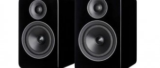
The reverse conversion from electrical vibrations to acoustic ones is carried out using loudspeakers built into radios and televisions, as well as separate speaker systems and headphones.
Sound refers to acoustic vibrations in the frequency range from 16 Hz to 20,000 Hz
Sound refers to acoustic vibrations in the frequency range from 16 Hz to 20,000 Hz. Below (infrasound) and above (ultrasound), the human ear cannot hear, and within the sound range, hearing sensitivity is very uneven, its maximum occurs at a frequency of 4 kHz. To hear sounds of all frequencies equally loud, you need to play them at different levels. This technique, called loudness compensation, is often implemented in household equipment, although its result cannot be considered unambiguously positive.
Rice.
2. Equal loudness curves (Click on the image to enlarge)
The physical properties of sound are usually presented not in linear, but in relative logarithmic quantities - decibels (dB), since this is much more clear in numbers and more compact in graphs (otherwise one would have to operate with quantities that have many zeros before and after the decimal point, and the latter would easily be lost against the background of the former). The ratio of two levels A and B in dB (say voltage or current) is defined as:
Сu [dB] = 20 lg A/B. If we are talking about powers, then Cp [dB] = 10 lg A/B.
In addition to the frequency range, which determines the sensitivity of human hearing to the pitch of sound, there is also the concept of a loudness range, which shows the sensitivity of the ear to the volume level and covers the interval from the quietest sound audible (sensitivity threshold) to the loudest, beyond which lies the pain threshold. The sensitivity threshold is taken as a sound pressure of 2 x 10⁻⁵ Pa (Pascal), and the pain threshold is a pressure 10 million times greater. In other words, the audibility range, or the pressure ratio of the loudest sound to the quietest sound, is 140 dB, which significantly exceeds the capabilities of any audio equipment due to its own noise. Only high-resolution digital formats (SACD, DVD Audio) are matched to a theoretical limit of dynamic range (the ratio of the loudest sound reproduced by the equipment to the noise level) of 120 dB, a CD provides 90 dB, a vinyl record provides about 60 dB.
Rice. 3. Hearing sensitivity range
Only high-definition digital formats (SACD, DVD Audio) approach the theoretical dynamic range limit
Noise is always present in the audio path. This includes both the intrinsic noise of the amplifying elements and external noise. Signal distortions are divided into linear (amplitude, phase) and nonlinear, or harmonic. In the case of linear distortions, the signal spectrum is not enriched with new components (harmonics), only the level or phase of existing ones changes. Amplitude distortions that violate the original level relationships at different frequencies lead to audible timbre distortions. For a long time it was believed that phase distortions were not critical for hearing, but today the opposite has been proven: both timbre and sound localization are largely dependent on the phase relationships of the frequency components of the signal.
Any amplification path is nonlinear
Any amplification path is nonlinear, so harmonic distortions always arise: new frequency components separated in frequency by 3, 5, 7, etc. from the tone generating them (odd harmonics) or in 2, 4, 6, etc. times (even). The threshold for the noticeability of harmonic distortions varies greatly: from several tenths and even hundredths of a percent to 3-7%, depending on the composition of the harmonics. Even-numbered harmonics are less noticeable because they are in consonance with the fundamental tone (the difference in frequency is twice that of an octave).
In addition to harmonic distortions, intermodulation distortions occur, which are the difference products of the frequencies of the signal spectrum and their harmonics. For example, at the output of an amplifier, the input of which is supplied with two frequencies 8 and 9 Hz (with a rather nonlinear characteristic), a third one (1 kHz) will appear, as well as a number of others: 2 kHz (as the difference between the second harmonics of the fundamental frequencies), etc. . Intermodulation distortion is especially unpleasant to the ear because it creates many new sounds, including those that are dissonant with respect to the main ones.
What an audiophile can hear and not only hear, but also explain, may turn out to be completely invisible to the average listener
Noise and distortion are largely masked by the signal, but they themselves mask low-level signals that disappear or become indistinct. Therefore, the higher the signal-to-noise ratio, the better. Actual sensitivity to noise and distortion depends on individual hearing characteristics and its training. The level of noise and distortion that does not affect speech transmission may be completely unacceptable for music. What an audiophile can hear and not only hear, but also explain, may turn out to be completely invisible to the average listener.
ANALOG AUDIO TRANSMISSION
Traditionally, audio signals were transmitted over wires and also over the airwaves (radio).
There are unbalanced transmission lines (classical wire) and balanced ones. Unbalanced has two wires: signal (direct) and return (ground). This line is very sensitive to external interference, so it is not suitable for transmitting signals over long distances. Often implemented using a shielded wire, the shield is connected to ground.
Rice. 4. Unbalanced shielded line
A balanced line involves three wires: two signal wires, through which the same signal flows, but in antiphase, and ground. On the receiving side, common-mode interference (induced on both signal wires) is mutually subtracted and completely disappears, and the level of the useful signal doubles.
Rice. 5. Balanced shielded line
Unbalanced lines are usually used inside devices and over short distances, mainly in user paths. In the professional sphere, balance dominates.
In the pictures, the screen connection points are shown conditionally, since they have to be selected “in place” each time to achieve the best results. Most often, the screen is connected only on the signal receiver side.
Unbalanced lines are usually used inside devices and over short distances, mainly in user paths. In the professional sphere, balance prevails.
Audio signals are normalized by the effective voltage level (0.707 of the amplitude value):
- microphone 1-10 mV (for microphones without a built-in amplifier),
- linear 0.25-1 V, usually 0.7 V.
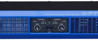
At the output of the power amplifier, from which the signal goes to the speakers, its level is much higher and can reach (depending on the volume) 20-50 V at currents up to 10-20 A. Sometimes - up to hundreds of volts, for broadcast lines and sounding of open spaces .
Cables and connectors used:
- for balanced lines and microphones - shielded pair (often twisted), 3-pin XLR connectors or terminals, screw or clamp;
Rice. 6. Connectors for balanced lines: terminals and XLR
- for unbalanced lines - shielded cable, RCA (“tulip”) connectors, less often DIN (as well as GOST), as well as various plugs;
Rice. 7. Unbalanced line connectors: RCA, 3.5mm and 6.25mm plugs
- for high-power loudspeaker signals - unshielded (with rare exceptions) large-gauge speaker cables, terminals or clamps, banana or needle connectors
Rice. 8. Speaker cable connectors
The quality of connectors and cables plays a significant role, especially in high-quality audio systems
The quality of connectors and cables plays a significant role, especially in high-quality audio systems. The materials of the conductor and dielectric, cross-section, and geometry of the cable matter. The most expensive models of interconnect and speaker cables use ultra-pure copper and even solid silver, as well as Teflon insulation, which is characterized by a minimal level of dielectric absorption, which increases signal loss, and unevenly across the frequency band. The cable products market is very diverse; often different models of the same quality differ from each other only in price, and many times over.
Any cables are characterized by analog signal losses, which increase with increasing frequency and transmission distance. Losses are determined by the ohmic resistance of the conductor and contacts in the connectors, as well as distributed reactive components: inductance and capacitance. In essence, the cable is a low-pass filter (cuts high frequencies).
In addition to transmission over different distances, signals often have to be branched and switched. Switchers (input selectors) are an integral part of many components of the audio path, both professional and consumer. There are also specialized distribution amplifiers that split the signal and ensure matching with the transmission line and other components in terms of level and impedances (and often compensate for roll-off at high frequencies) and switches, conventional (several inputs and one output) and matrix (multiple inputs and outputs) ).
ANALOG AUDIO PROCESSING
Any processing of an analog audio signal is accompanied by certain losses in its quality (frequency, phase, and nonlinear distortions occur), but it is necessary. The main types of processing are as follows:
- amplifying the signal to the level required for transmission, recording or playback by a loudspeaker: by applying a signal from a microphone to a speaker, we will not hear anything: we need to first amplify it in level and power, while providing the ability to adjust the volume.
Rice. 9
- frequency filtering: infrasound, which is harmful to health at certain frequencies, and ultrasound are cut off from the useful sound range (20 Hz - 20 kHz). In many cases, the range is deliberately narrowed (the voice telephone channel has a band from 300 Hz - 3400 Hz, the frequency band of meter radio stations is significantly limited). For acoustic systems, which usually have 2-3 bands, separation is also necessary, which is usually carried out in crossover filters already at the level of the amplified (powerful) signal.
Rice. 10. Crossover circuit for a three-way speaker system
- frequency correction (equalizing): tone adjustment, compensation for uneven output due to the acoustic properties of the room, compensation for losses in transmission lines, studio processing to achieve the desired “color” of sound, suppression of parasitic acoustic feedback (“whistle”), etc. d.
Rice. 11. Example of an equalizer device
- noise suppression: there are special dynamic noise reduction circuits that analyze the signal and narrow the band in proportion to the level and frequency of the RF components (“denoisers”, “dehissers”). In this case, the noise located above the signal band is cut off, and the remaining noise is more or less masked by the signal itself. Such schemes always lead to very noticeable signal degradation, but in some cases their use is appropriate (for example, when working with recorded speech or in intercom radio stations). For analogue recording equipment, noise suppressors based on compressors/expanders (“compander”, for example, Dolby B, dbx systems) are also used, the operation of which is less noticeable to the ear.
- impact on dynamic range: in order for the playback of music programs on ordinary household systems, including car radios, to be sufficiently rich and expressive, the dynamic range is compressed, making quiet sounds sound louder. Otherwise, apart from occasional bursts of fortissimo (on classical music), you will have to listen to silence from the speakers, especially given the noisy environment. Devices called compressors are used for this purpose. In some cases, on the contrary, it is necessary to expand the dynamic range, then expanders are used. And to prevent exceeding the maximum level, which will lead to clipping (limitation of the signal from above, accompanied by very high nonlinear distortions, perceived as wheezing), limiters are used in studios. They typically provide “soft” clipping rather than simply cutting off the tops of the signal;
Rice. 12. Example of a studio dynamics processor
- special effects for studios, EMR, etc.: sound engineers and musicians have a large amount of special equipment at their disposal to give the sound the desired color or achieve a certain effect. These are various distorters (the sound of an electric guitar becomes hoarse, grainy), wah-wah attachments (amplitude modulation, causing a characteristic “croaking” effect), enhancers and exciters (devices that affect the color of the sound, in particular, they can give the sound a “tube” tint ); flangers, choruses, etc.
Rice. 13. Examples of processors and attachments for electric guitars
- sound mixing, echo/reverberation: recording in studios is usually done in multi-channel form, then using mixers the phonogram is mixed into the required number of channels (most often 2 or 6). In this case, the sound engineer can “push forward” one or another solo instrument recorded on a separate track, and change the ratio of the volumes of different tracks. Sometimes multiple copies of a lower level are superimposed on the signal with a certain time shift, thereby simulating natural reverberation (echo). Currently, similar and other effects are achieved mainly using signal processors that process digital signals.
Rice. 14. Modern mixing console
RECORD ANALOG AUDIO
It is believed that mechanical recording of sound was first implemented by Edison in 1877, when he invented the phonograph - a roller covered with a layer of soft staniol, onto which a trace was made with a needle transmitting air vibrations (later wax was used instead of staniol, and the method itself began to be called depth recording , since the track was modulated in depth). However, in the same year, the Frenchman Charles Cros submitted an application to the Academy of Sciences regarding his invention - the sound was recorded on a flat glass disk, covered with soot, using a needle connected to the membrane, a transverse track was obtained, then the disk was supposed to be illuminated and photocopies were made from it for replication (the method itself had yet to be developed). In the end, transverse recording, which turned out to be much more perfect than deep recording, gave rise to gramophone recording. Three companies appeared in the world that serially produced records (CBS in America, JVC in Japan, Odeon in Germany - this company gave the world a double-sided record) and devices for playing them. The name “gramophone” comes from Deutsche Gramophon (Germany), and gramophone from Pathé (France). Then they began to produce portable gramophones with a bell on a hinge, with an electric motor instead of a manual drive, and later with electromagnetic adapters. The records became more and more perfect, they contained more material in terms of playing time, and the frequency range, initially limited to 4 kHz, expanded. Vinylite replaced fragile shellac, and short-lived steel needles gave way to sapphire, then diamond. The era of stereo began: two tracks were cut into one groove at an angle of 45°. By the beginning of the 80s of the last century, when there was a global transition to the digital audio format, the vinyl record reached the apogee of its development.
Rice. 15. Gramophone, gramophone, electric player
Magnetic recording is more advanced and has long been used in studios. The first magnetic recording device, the telegraph, was created by Waldemar Paulsen (Denmark) in 1878, and the recording was made on a steel wire (a piano string). In the 20s of the 20th century, tape recorders using magnetic tape appeared. Mass production of tape recorders began in the 40s. First, magnetic tapes appeared on cellulose and then on lavsan base. Audio signals are recorded onto longitudinal tracks using a writing (or universal) head with a magnetic gap. The tape is pulled close to the head gap, and a residual magnetization path is formed on it. The nonlinear part of the characteristic is “blurred” using a high-frequency bias current (usually about 100 kHz), on which the useful signal is superimposed. Studio analog tape recorders, along with digital ones, are still used for primary recording of phonograms. Household ones come in two- and three-head types (separate recording, playback and erasing heads or erasing and universal heads). Sometimes there are two playback heads if reverse is provided.
Even with very careful handling, magnetic tape begins to crumble over time
Magnetic tape has noise that decreases (partially moves beyond the audible range) as the feed speed increases. Therefore, studio tape recorders have a speed of 38, while household reel-to-reel tape recorders have a speed of 19 and 9.5 cm/s. For household cassette recorders, a speed of 4.76 cm/s was adopted. Tape noise is effectively suppressed using the Dolby B compander system: during recording, the level of the high-frequency part for weak signals is raised by 10 dB, and during playback it is lowered by the same amount.
Professional analog magnetic recording at high speed provides very high quality. It was on magnetic master tapes that musical recordings were archived for a long time, and from them the phonogram was transferred to vinyl records with some loss of quality. However, even with very careful treatment, magnetic tape begins to crumble over time, it is characterized by gradual demagnetization, deformation, a copy effect (adjacent layers in the roll are mutually magnetized), and is susceptible to the influence of external magnetic fields. It is also difficult to quickly find the desired fragment (although this inconvenience applies more to the domestic sphere). Therefore, with the advent of digital formats, Sony, the owner of a huge archive of CBS/Columbia recordings, concerned with the problem of preserving priceless original recordings of the second half of the 20th century, developed a recording method in the discrete pulse-width modulation format (DSD stream - Direct Stream Digital, which later gave rise to custom Super Audio CD format). If analog magnetic recording ensures the preservation of a phonogram for several decades with gradually increasing losses, then digital archives are eternal and can withstand an unlimited number of copies without any degradation. For this, as well as for many other reasons (service advantages, versatility, enormous processing capabilities), digital audio formats are now becoming increasingly widespread.
RECEIVING DIGITAL AUDIO SIGNAL
According to the Kotelnikov-Shanon theorem, a discrete signal can subsequently be completely reconstructed provided that the sampling frequency is at least twice the upper frequency of the signal spectrum
A digital signal is obtained from an analog signal or synthesized directly in digital form (in electric musical instruments). Analog-to-digital conversion involves two main operations: sampling and quantization. Discretization is the replacement of a continuous signal with a number of samples of its instantaneous values, taken at equal intervals of time. According to the Kotelnikov-Shanon theorem, a discrete signal can subsequently be completely reconstructed provided that the sampling frequency is at least twice the upper frequency of the signal spectrum. Then the samples are quantized by level: each of them is assigned a discrete value closest to the real one. The quantization accuracy is determined by the bit depth of the binary representation. The higher the bit depth, the more quantization levels (2N, where N is the number of bits) and the lower the quantization noise - errors due to rounding to the nearest discrete level.
Rice. 16. Digitizing an analog signal and obtaining digital samples
The CD format assumes a sampling rate of 44.1 kHz and a bit depth of 16 bits. That is, 44 thousand samples per second are obtained, each of which can take one of 216 = 65536 levels (for each of the stereo channels).
The most advanced consumer audio formats are DVD Audio and Super Audio CD (SACD)
In addition to the 44.1 kHz / 16-bit format, others are used in digital recording. Studio recording is usually made with a bit depth of 20-24 bits. The data is then converted into standard CD format by conversion. The extra bits are then discarded or (better) rounded, sometimes pseudo-random noise is mixed in to reduce quantization noise (dither).
The most advanced consumer audio formats are DVD Audio and Super Audio CD (SACD). DVD Audio adopts the MLP lossless data compression algorithm developed by Meridian. And SACD, unlike other formats, does not use pulse-code modulation (PCM), but one-bit DSD stream coding (discrete pulse-width modulation). SACD discs come in single-layer and double-layer (hybrid) formats, with a regular CD layer.
The most popular audio media today remains the CD, despite certain limitations in sound quality noted by audiophiles. The reason for them is the low sampling frequency: to accurately restore signals close to the upper limit of the audio range, a filter is needed that is not physically implementable (its impulse response covers the negative time region). This is compensated to a certain extent by digital filtering with increasing sampling frequency and bit depth. To ensure uninterrupted real-time playback, the data on the disc is recorded with redundant encoding (Reed-Solomon code).
Digital media, sampling rates and encoding bits
| Carrier | Authorship | Dimensions | Playing time, min. | Col. channels | Fs, kHz | Bits |
| CD-DA | Sony, Philips | 120, 90 mm | up to 90 | 2 | 44,1 | 16 |
| S-DAT | cassette, 3.81 mm tape | 2 | 32, 44,1, 48 | 16 | ||
| R-DAT | cassette, 3.81 mm tape | 2, 4 | 44,1 | 12, 16 | ||
| DASH | tape 6.3, 12.7 mm | 2…48 | 44,056, 44,1, 48 | 12, 16 | ||
| DAT | Alesis | S-VHS cassette | 60 | 8 | 44,1, 48 | 16, 20 |
| DCC | Philips | cassette | 2, 4 | 32, 44,1, 48 | 16, 18 | |
| MiniDisk | Sony | 64 mm | 74 | 2, 4 | 44,1 | 16 |
| DVD Audio | 120 mm | 5.1 | 192 | 24 | ||
| SACD | Sony, Philips | 120 mm | 2, 5 | 2800 | 1 |
Digital audio transmission requires a broadband link, especially for uncompressed high-resolution multi-channel streams.
DIGITAL AUDIO TRANSMISSION
Communication lines for transmitting digital audio can be cables, optical lines and radio air.
To transmit PCM signals over wired lines, AES/EBU (balanced, coaxial), S/PDIF (unbalanced coaxial) interfaces have been developed, providing the transmission of several signals (clock frequency, digital word rate, channel data) over one wire. Inside the devices, these signals are transmitted separately, encoded at the output of the transport mechanism, and at the input of the digital-to-analog converter (in two-block systems) they are again separated in the digital receiver.
Typically, high-quality coaxial cable is used to transmit digital audio. There are also S/PDIF converters for fiber optic lines: AT&T ST and Toslink (the latter is standard for consumer equipment). And also for the use of twisted pairs as part of Ethernet cable networks. The medium for distributing compressed audio in the form of archived files is the Internet.
Rice. 17. Optical cable with Toslink connector
Like any digital signal, digitized audio is distributed and switched using special devices - distribution amplifiers, conventional and matrix switchers.
There is a factor that negatively affects digital signals and often negates almost all the advantages of digital audio over analogue, including the ability to repeatedly copy, transmit and archive programs without loss of quality - we are talking about jitter. Jitter is the phase jitter, or uncertainty in the moment of transition from 0 to 1 and vice versa. This happens due to the gradual deformation of rectangular pulses with almost ideal fronts, which become more and more flat due to the reactive elements of the cables, which leads to uncertainty in the moment of the drop, although the steepness of the fronts in each subsequent digital device is completely restored. All modern digital devices successfully combat jitter using reclocking units. For more information, see the Signal Switching and Control brochure.
Fig. 18. Distribution and switching
Compressed audio formats are used for transmission and recording on various digital media: Dolby Digital (AC-3) and DTS. This allows you to place a full-length film with multi-channel audio, as well as various additional materials, on a 4.7 GB DVD Video disc. The Dolby Digital format offers 5 independent channels: 2 front, 2 rear and 1 subwoofer for special effects. Compression is performed using an adaptive MPEG Audio algorithm, based on the psychoacoustic characteristics of sound perception and ensuring minimal noticeability of compression. All this allows you to recreate a full-fledged three-dimensional sound panorama. However, for high-quality music playback, Dolby Digital is much less suitable than CD, having a lower resolution. The bit rate in Dolby Digital mode (samples for each channel are transmitted one after another) is 384-640 kbps, while in the usual two-channel CD format it is 1411.2 kbps. The Dolby Digital 5.1 format has been improved several times, mainly in the direction of increasing the number of channels. Now available is the DD 7.1 version, which provides 2 front, 2 side and 2 rear channels, not counting the special effects channel (the DD 6.1 modification with one rear channel is also known).
The DTS format has a lower compression ratio and a higher data rate - 1536 kbps. Therefore, it is used not only for encoding multi-channel soundtracks on DVD Video, but also for multi-channel audio
Jitter and quantization noise
ADCs also consider concepts such as jitter and quantization noise. Let's take a brief look at what they are.
So, jitter is called the phase jitter of a digital signal. In general, these are unwanted (random) phase and/or frequency deviations of the signal that are transmitted by the carrier. It may occur due to instability of the master oscillator due to changes in the parameters (time or frequency) of the transmission line. Jitter can manifest itself in the form of delays, signal attenuation, and noise.
In an ADC, jitter refers to the shift in the time period of the quantization moments during the digitization of analog audio. This is due to the imperfection of the clock signal, which sets the moment of sampling.
Quantization noise refers to errors that occur during the conversion of an analog signal to digital. May occur due to rounding or truncation of signals. Both of these phenomena affect the quality of the final sound. Therefore, to avoid these errors, during ADC, signal transfer from one register to another should be carried out as accurately as possible. In addition, it is important to use high-quality equipment for signal conversion: this applies to sound recording devices, power supplies, and quartz oscillators.
2.1. Binary system
Involves the use of binary calculus to display certain values. In the digital audio industry, it is used to display instantaneous voltage values obtained by measuring the instantaneous amplitude values of an analog signal. However, if in the analog world, the accuracy of measurement is a function of the number of decimal places, then in the binary system it is the number of zeros and ones in one digital “word”. The length of such a word is called bit depth. Below is a table showing an 8-bit system.
In such a system it is possible to represent a maximum of 256 different values. The astute reader will note that negative numbers are represented by a number word starting with one, while positive numbers begin with zero. In addition, there will always be one less positive value than negative value, and this is because one of the values is “spent” to represent zero, which, as we know, is neither positive nor negative. The number of possible values can be easily calculated using the following formula:
A digital word consists of a series of zeros and ones. The first number in the word is called MSB (Most Significant Bit), while the last number is called LSB (Least Significant Bit). MSB is the most informative, and LSB gives the most accurate coordinates.
To illustrate, we can compare MSB to the number before the decimal point, while LSB to the last number after the decimal point. For example, let's take the number 5.05683097. The first number (5) is MSB and carries the most important information. Without it, we will not know that the entire number is close to 5. While the last number (7) carries the most accurate information about the value of the number. This is a very rough analogy, but it can be quite suitable for illustration.
This calculation demonstrates the method by which certain values are obtained using zeros and ones. In this case, 01111100 equals 124. One by one, take the value (0 or 1) and multiply by 2 (since there can be either zero or one) in increasing degrees. Start with LSB and degree zero. As you know, any number multiplied by zero will equal zero. Therefore, when calculating, only units and their serial number in the digital word, which determines the degree, are counted.
The volume of the resulting file will depend on the sampling frequency, bit depth and, of course, the time during which the digitization was carried out. The volume can be easily calculated using the following formula:
This formula allows you to calculate the volume for one minute of a mono signal. To obtain volume for a longer time and multi-channel sound, you need to multiply the result by the number of minutes and channels.
Of course, the greater the number of available values (bit depth), the more accurately one can represent the amplitude value of the original signal at a given point in time, however, in any case, the number of possible values cannot be infinite and will always be limited. Therefore, in order to represent the continuous values of the amplitude of the original signal in discrete form, some rounding is performed to values known to the system.
Digital to analog conversion
Once the audio has been converted to a digital signal, it must be converted back to analog audio in order to be heard. Digital-to-analog converters are used for this. Using audio interfaces as an example, let's look at how this process occurs. Analog audio enters the mixer (analog input) and is sent to the ADC where it is quantized and sampled. The resulting digital output signal goes through the same process, only in reverse: the data passes through a digital-to-analog converter, which turns it into an analog signal. In the diagram the process looks like this:
How DACs build a wave
A DAC is a digital-to-analog converter, an element that converts digital sound into analog. We will look superficially at the basic principles. If the comments indicate an interest in considering a number of points in more detail, a separate material will be released.
Multibit DACs
Very often, a wave is represented as steps, which is due to the architecture of the first generation of multi-bit R-2R DACs, which operate similarly to a relay switch.
The DAC input receives the value of the next vertical coordinate and at each clock cycle it switches the current (voltage) level to the appropriate level until the next change.
Although it is believed that the human ear can hear no higher than 20 kHz, and according to Nyquist theory it is possible to restore the signal up to 22 kHz, the question remains about the quality of this signal after restoration. In the high-frequency region, the resulting “stepped” waveform is usually far from the original one. The easiest way out of the situation is to increase the sampling frequency when recording, but this leads to a significant and undesirable increase in file size.
An alternative is to artificially increase the DAC playback sampling rate by adding intermediate values. Those. we imagine a continuous wave path (gray dotted line) smoothly connecting the original coordinates (red dots) and add intermediate points on this line (dark purple).
When increasing the sampling frequency, it is usually necessary to increase the bit depth so that the coordinates are closer to the approximated wave.
Thanks to intermediate coordinates, it is possible to reduce the “steps” and build a wave closer to the original.
When you see a boost function from 44.1 to 192 kHz in a player or external DAC, it is a function of adding intermediate coordinates, not restoring or creating sound in the region above 20 kHz.
Initially, these were separate SRC chips before the DAC, which then migrated directly to the DAC chips themselves. Today you can find solutions where such a chip is added to modern DACs, this is done in order to provide an alternative to the built-in algorithms in the DAC and sometimes get even better sound (as for example, this is done in the Hidizs AP100).
The main refusal in the industry from multibit DACs occurred due to the impossibility of further technological development of quality indicators with current production technologies and the higher cost compared to “pulse” DACs with comparable characteristics. However, in Hi-End products, preference is often given to old multi-bit DACs rather than new solutions with technically better characteristics.
Switching DACs
At the end of the 70s, an alternative version of DACs based on a “pulse” architecture – “delta-sigma” – became widespread. Pulse DAC technology enabled the emergence of ultra-fast switches and allowed the use of high carrier frequencies.
The signal amplitude is the average value of the pulse amplitudes (pulses of equal amplitude are shown in green, and the resulting sound wave is shown in white).
For example, a sequence of eight cycles of five pulses will give an average amplitude (1+1+1+0+0+1+1+0)/8=0.625. The higher the carrier frequency, the more pulses are smoothed and a more accurate amplitude value is obtained. This made it possible to present the audio stream in one-bit form with a wide dynamic range.
Averaging can be done with a regular analog filter, and if such a set of pulses is applied directly to the speaker, then at the output we will get sound, and ultra high frequencies will not be reproduced due to the high inertia of the emitter. PWM amplifiers work on this principle in class D, where the energy density of pulses is created not by their number, but by the duration of each pulse (which is easier to implement, but cannot be described with a simple binary code).
A multibit DAC can be thought of as a printer capable of applying color using Pantone inks. Delta-Sigma is an inkjet printer with a limited range of colors, but due to the ability to apply very small dots (compared to an antler printer), it produces more shades due to the different density of dots per unit surface.
In an image, we usually do not see individual dots due to the low resolution of the eye, but only the average tone. Likewise, the ear does not hear impulses individually.
Ultimately, with current technologies in pulsed DACs, it is possible to obtain a wave close to what should theoretically be obtained when approximating intermediate coordinates.
It should be noted that after the advent of the delta-sigma DAC, the relevance of drawing a “digital wave” in steps disappeared, because This is how modern DACs do not build a wave in steps. It is correct to construct a discrete signal with dots connected by a smooth line.
Are switching DACs ideal?
But in practice, not everything is rosy, and there are a number of problems and limitations.
Because Since the overwhelming number of records are stored in a multi-bit signal, conversion to a pulse signal using the “bit to bit” principle requires an unnecessarily high carrier frequency, which modern DACs do not support.
The main function of modern pulse DACs is to convert a multi-bit signal into a single-bit signal with a relatively low carrier frequency with data decimation. Basically, it is these algorithms that determine the final sound quality of pulse DACs.
To reduce the problem of high carrier frequency, the audio stream is divided into several one-bit streams, where each stream is responsible for its bit group, which is equivalent to a multiple of the carrier frequency of the number of streams. Such DACs are called multibit delta-sigma.
Today, pulsed DACs have received a second wind in high-speed general-purpose chips in products from NAD and Chord due to the ability to flexibly program conversion algorithms.
Volume in digital audio
The volume of digital signals should not exceed 0db. If we do not take this nuance into account, we end up with digital signal overload at the input or output. This value is the highest point, that is, the peak value. It allows you to record high-quality sound and perceive it properly. If this value is exceeded, the signal is distorted and the equipment may be damaged due to overload.
In addition to the peak point, the concept of loudness also includes such an element as the RMS value. This concept defines the actual loudness level, which reflects the recording density and provides information about the loudness that our hearing is capable of perceiving. RMS is denoted in decibels, but with a minus value: the louder the sound, the higher the numerical value of RMS (maximally loud - -6db, maximally quiet - -20db). Optimal digital volume values are -12db - -10db.
2.3. Resolution or bit depth
This concept refers to the length of a digital word, which means the number of available values to display the amplitude of the original signal. From this we can conclude: the higher the bit depth, the more detailed the original signal can be represented. What about dynamic range? That is, what is the maximum level the system can display? This is also directly related to the bit depth. Each bit expands the dynamic range by 6.02 dB. The dynamic range of any system can be calculated using the following formula:
For example, the dynamic range of a 16-bit system is 96.3 dB, while a 24-bit system is 144.4 dB. However, dynamic range should not be confused with signal to noise ratio! As stated earlier, quantization errors cause noise of 3 dB, which is the minimum noise floor of any digital system!
In digital formats, 0 dBFS (Full Scale) is taken as the highest signal value and counted in the negative direction. For example, in a 16-bit system with a dynamic range of 96.3 dB, the highest value would be 0 dBFS and the lowest would be -96.3 dBFS.
Now let's talk about signals whose level exceeds 0 dBFS. What will happen in this case? If in the world of analogue technologies, and especially tube ones, a certain degree of overdrive can advantageously color the sound, then in numbers any overcoming of a barrier equal to the maximum level of a given system will be expressed in clipping, that is, equating all signals exceeding this level to the maximum possible in this system. This results in very unpleasant sounds, not to mention the fact that the useful signal is lost forever. This means that you need to be very careful when adjusting the level. You should not strive for the “ceiling” itself. This is a habit left over from the days of magnetic tape, whose dynamic range was 60 dB at best, excluding hiss and other artifacts. Then, there really was a need to record the signal as close as possible to the limit of the possible level, and sometimes even beyond it, in order to move as far as possible from noise. Digital technology provides us with 96.3 dB (16 bit) and 144.4 dB (24 bit) dynamic range and it would be very stupid not to use it. The author does not mean recording at very low levels, which leads to partial use of all possible values in a given system, but the competent use of the capabilities of modern technology. Remember: digital distortion is BAD! Very bad!
As can be seen from the illustration, the non-selected part of the signal has peak values equal to 0 dBFS, while the selected part, although only 1 dB different from the non-selected part, is noticeably distorted. The part of the signal exceeding the maximum level is simply lost forever. This phenomenon is called clipping.
Here, indicative equipment plays a great role, which, if used competently and correctly, can help avoid overloads and, as a result, distortions. For more complete and detailed information, please refer to the “Volume and Level” chapter. Calibrating the levels of all equipment used to a single standard will also help to avoid distortions.
Stereophony and panorama
Stereophony is the recording, transmission or playback of an audio signal, in which auditory information about the location of the source of this signal is stored using the method of laying out the sound in a pair or more independent audio channels. With the right placement of music broadcasters, you can achieve immersive surround sound. This creates the feeling that sound with different phases comes from different sources.
Panorama is, in fact, the established direction of a sound source according to three spatial characteristics - distance, height and direction. Thanks to panning we get:
- uniform distribution of sound energy;
- differentiation of signal sources with the same range and sound frequency;
- special effects.
To create a high-quality sound panorama, it is necessary to correctly arrange the elements that supply the signal. Ideally it looks like this:
That is, the center channel of the sound source should be located between the left and right channels. This placement of stereo sources will allow you to get the most complete, clear and rich sound.
Basic audio file formats
In fact, there are a lot of formats with which you can read audio files. But there are those that have received universal recognition. All of them are divided into three groups:
- uncompressed audio formats;
- with lossless compression;
- with lossy compression.
Let's look at the main audio file formats:
- WAV is the first audio format that could be processed by computer programs at a high professional level. Disadvantage: recording takes up too much space.
- CDs - The .cda extension cannot be edited, but it can be reformatted and saved with any audio processing program.
- MP3 codec is a universal format that compresses audio files as much as possible.
- AIFF files - the format supports monophonic and stereophonic data of 8 and 16 bits in size, was originally developed for the Macintosh, but after additional development it can be used on other OS platforms.
- OGG is a popular format, but it has disadvantages such as the use of its own codecs and decoders and overloading the computer's system resources.
- AMR is a low-quality audio format.
- The MIDI format allows you to edit a recording by pressing keys, changing tempo, key, pitch, and adding effects.
- FLAC is a format that reproduces audio in high quality.
DSD format
After the widespread use of delta-sigma DACs, it was quite logical for the emergence of a format for recording binary code directly to delta-sigma encoding.
This format is called DSD (Direct Stream Digital). The format was not widely used for several reasons. Editing files in this format turned out to be unnecessarily limited: you cannot mix streams, adjust volume, or apply equalization. This means that without loss of quality, you can only archive analog recordings and produce two-microphone recording of live performances without further processing. In a word, you can’t really make money.
In the fight against piracy, SA-CD format discs were not (and are still not) supported by computers, which makes it impossible to make copies of them. No copies – no wide audience. It was possible to play DSD audio content only from a separate SA-CD player from a proprietary disc. If for the PCM format there is an SPDIF standard for digital data transfer from a source to a separate DAC, then for the DSD format there is no standard and the first pirated copies of SA-CD discs were digitized from the analog outputs of SA-CD players (although the situation seems stupid, but in reality some recordings were released only on SA-CD, or the same recording on Audio-CD was deliberately made of poor quality to promote SA-CD).
The turning point occurred with the release of SONY game consoles, where the SA-CD disc was automatically copied to the console’s hard drive before playback. Fans of the DSD format took advantage of this. The appearance of pirated recordings stimulated the market to release separate DACs for playing DSD streams. Most external DACs with DSD support today support USB data transfer using the DoP format as a separate encoding of the digital signal via SPDIF.
Carrier frequencies for DSD are relatively small, 2.8 and 5.6 MHz, but this audio stream does not require any data reduction conversion and is quite competitive with high-resolution formats such as DVD-Audio.
There is no clear answer to the question of which is better, DSP or PCM. It all depends on the quality of implementation of a particular DAC and the talent of the sound engineer when recording the final file.