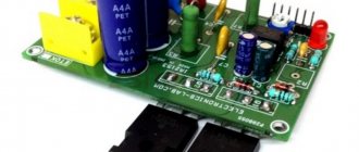
Schematic diagram of a network switching power supply for ULF, output voltage +-25V at a current of up to 4.5A (approximately 200W). The circuit is assembled on an IR2153 chip and IRF740 transistors. Useful tips on assembling and setting up the device are provided.
I would like to offer a short overview of this scheme. Once there was a need for a person to assemble a simple ULF, and a housing from an old “radio engineering” preamplifier was found.
There is a lot of space in the case, but it was not possible to fit the network transformer; the case turned out to be too small in height. It was decided to assemble a switching power supply on the ir2153 chip, there was just one lying around idle.
Switching power supply circuit for IR2151-IR2153
Switching power supply for IR2151-IR2153
The advantage of any switching power supply is that there is no need to wind or buy a bulky transformer. All you need is a transformer with several turns. This
power supply to make yourself and requires few parts. And the basis is that the power supply is based on the IR2151 chip.
A characteristic feature of this power supply is its simplicity and repeatability. The circuit contains a small number of components and has proven itself for more than two years. A standard step-down transformer from a computer power supply is used as a pulse transformer.
At the input there is a PTC thermistor - a semiconductor resistor with a positive temperature coefficient, which sharply increases its resistance when a certain characteristic temperature TRef is exceeded. Protects power switches at the moment of switching on while capacitors are charging.
Diode bridge at the input for rectifying the mains voltage to a current of 10A. A “vertical” type diode assembly was used, but a “stool” type diode assembly can be used.
A pair of capacitors at the input is taken at the rate of 1 microfarad per 1 W. In our case, the capacitors will “pull” a load of 220W.
The damping resistance in the driver power circuit is 2 W. Preference is given to domestic resistors of the MLT-2 type.
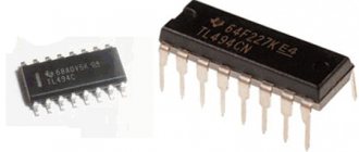
Driver IR2151 – for controlling the gates of field-effect transistors operating under voltages up to 600V. Possible replacement for IR2152, IR2153. If the name contains the index “D”, for example IR2153D, then the FR107 diode in the driver harness is not needed. The driver alternately opens the gates of the field-effect transistors with a frequency set by the elements on the legs Rt and Ct.
Field effect transistors are preferably used from IR. Select a voltage of at least 400V and with minimal open resistance. The lower the resistance, the lower the heating and the higher the efficiency. We can recommend IRF740, IRF840, etc. A reference book on field-effect transistors from IR in Russian can be downloaded here. Attention! Do not short-circuit the flanges of field-effect transistors; When installing on a radiator, use insulating gaskets and bushing washers.
A standard step-down transformer from a computer power supply. As a rule, the pinout corresponds to that shown in the diagram. Homemade transformers wound on ferrite tori also work in this circuit. Homemade transformers are calculated for a conversion frequency of 100 kHz and half the rectified voltage (310/2 = 155V).
When choosing a transformer, you should choose one whose pins on the original board are short-circuited as shown in the diagram. It is important. Otherwise, you should close it as it was done on the board from which you are removing the transformer.
Output diodes with a recovery time of no more than 100 ns. These requirements are met by diodes from the HER (High Efficiency Rectifier) family. Not to be confused with Schottky diodes.
The output capacity is a buffer capacity. Do not install a capacitance of more than 10,000 microfarads.
Printed circuit board
Practice has shown that this application does not require a special organization of feedback, inductive power supply filters, snubbers and other “bells and whistles” inherent in pulse converters. One way or another, the typical defects characteristic of “poor nutrition” (background and extraneous sounds) are not felt in the sound.
Field-effect transistors do not get very hot during operation.
Passive cooling is sufficient for them. IR field-effect transistors are very resistant to thermal destruction and operate up to temperatures of 150? C. But this does not mean that they should be operated in such a critical mode. For such cases, you will need to organize active cooling, or, simply, install a fan.
Like any device, this power supply requires careful and careful assembly, correct installation of polar elements and caution when working with mains voltage. After turning off this power supply, no dangerous voltage remains in its circuits. A properly assembled power supply does not require configuration or adjustment.
radiostroi.ru
Switching Power Supply on IR2153.
About the article.
There are a lot of circuits in the global trash heap using this microcircuit and describing it like this... But how and why? Will it work? But the last question very often the answer is no!! There are a lot of “Miraculous” seals and advice to use exactly a 1000uF x 500V capacitor, which cannot be found or will cost half your salary. I will try to describe what I had to face when building the device, how it was decided, to reduce everything to simple and understandable principles, using which everyone can decide what they need.
About the “Irka” itself - IR2153.
The microcircuit is designed for use in electronic ballasts of economical lamps; these are devices of microscopic power, operate at frequencies of about 30 KHz, and do not have specially designed protection and control circuits. This gives something to think about! The IR2153 is low-power and can be powered simply through a pull-down resistor, and there is also separation for the upper and lower switches of the half-bridge, so there is no need to wind transformers or use optical separation of switch control signals. This makes the microcircuit attractive not only for amateurs, but also for serious brands that produce products in series!
And so, the project itself.
The goal was to build a simple, as universal as possible, power module with a power of about 200W. Scope of application from power supply of halogen lamps to UMZCH, etc. Oddly enough, in terms of the cost of materials, this module can compete with factory transformers for halogen lamps, and even more so in other areas of application.
Power supply - AC 250V 50..60Hz Output - 150V AC with a frequency of 50..60KHz to a replaceable transformer. Approximate power - 200W. Transformer in the photo: no-load voltage - 25V, load voltage 200W - 23.5V
The oscillograms are distinguished by a very smooth front (impulse rise), isn’t it? Even if you reduce the pulse frequency to 30 KHz, huge drafts from the Miller effect remain, these current pokes can be admired on the oscillograms. Nevertheless, you can hear, or rather read, that this is how everything works! ! You can trust this; the circuit will probably not light up right away, especially on a large radiator.
The driver is very weak (200mA per pulse), designed for low-power transistors, because this is a microcircuit for ballast in lamps! The driver in the form of transistor repeaters used in this project significantly improves the situation.
An external driver reduces the Miller effect and increases the efficiency of the unit. All these oscillograms were with a completely empty half-bridge output, no snubbers, not even a transformer winding. Now signals from loaded transistors. the signal is smooth and the transistors heat up little. IRF840 10KV transformer or + lds, load transformer 10KV on 3 cores 110pc15, loaded on a fluorescent lamp - a distorted form of short transformer.
Another moment, when at least the primary winding of the transformer is connected, the transistors stop heating and Miller’s pins disappear along the front, they disappear, but Miller doesn’t disappear anywhere, and here he is, he appears again, now on the decline of the pulse, on the oscillograms from the unit under load! Voila! And it is clear that even a powerful external driver had difficulty keeping the unit from catching fire. So a driver is needed to improve the reliability of the unit. The cost of the given driver is only 10% of the cost of IR 2153.
While I was cutting up the block, I assembled another driver, it crushes Miller even better, although the transistors are still the same, apparently due to increasing the gain of the cascade, during tests I simply cut off the existing driver seal and soldered the transistor. Circuit and oscillogram, block at idle.
Transformer(s).
At its core, a pulse transformer for forward-flow circuits is no different from a conventional 50Hz AC transformer. At idle, the current through the primary winding is determined by inductive reactance, is very insignificant, and should be exactly that way. A loaded transformer transforms the load resistance connected to the secondary winding, in accordance with the transformation ratio (the ratio of turns of the primary and secondary windings) and the current in the primary winding is determined by the transformed load resistance.
The thickness of the wires is determined by the maximum current, and the design of the winding; with multilayer windings, thicker wires are needed. As the frequency increases, the core transmits energy better, but magnetization reversal losses may increase; as the frequency decreases, the ferrite more easily enters saturation, which can cause a sharp decrease in the inductance of the primary winding by a factor of thousands and combustion of the block.
An example of a “folk” transformer, for a half-bridge 50..60 KHz.
Ferrite grade 2000NMS, from a line transformer TVS110pts15, primary winding 150V - 30..40 turns of wire, the secondary is calculated for the required voltage, based on the required voltage and the volts/turn ratio in the primary winding. For example, for this core: The power supply for the output stage is half-bridge 310V, then the pulse voltage on the primary winding of the transformer is 150V Primary winding at 150V - 30 turns (5V\turn) Secondary winding at 15V - 3 turns
If the secondary winding has a small number of turns and poor filling of the transformer window, then you can wind the secondary winding with several parallel conductors, which are then soldered in parallel, this way you can reduce the heating of the secondary winding and increase the magnetic coupling of the windings. For one such core, the throughput is approximately 500 W, and if necessary, the cores can be parallelized, proportionally reducing the number of turns of the primary winding, so for two cores you can take 20 turns, for three - 15 turns.
The design of such a transformer is of course not optimal, but it is easy to make at home and by winding the primary and secondary windings on different sides of the ferrite, you can achieve a soft connection between the windings, which can save the device in the event of a short circuit in the secondary winding.
Transformer from this project.
The core is made up of 8 rings TN2010-3E25, 5340nH (20.6×9.2×7.5mm) Primary winding 150V - 12 turns of wire in PVC insulation Secondary winding - 1 turn Here the weak link is the core material, suitable only for weak magnetic fields, can easily go into saturation and burn out the power supply. But in principle, the design is promising for amateurs, just choose a different material.
I hope that the proposed material will help interested parties decide on the necessary circuitry to create a device to suit their needs. Aaand.. remember any unexpected sneeze or unsoldered gate of a transistor will cause an instant and merciless PUGH, because... All nodes are galvanically connected; nothing can be saved.
Electronic ballasts. Simple electronic ballast on the IR2153 chip
Let's consider a simple electronic ballast circuit based on the IR2153 (IR2151) chip, shown in Fig. 3.14. Main parameters of IR2153
are:
- the maximum voltage at the VB pin relative to the common wire is 600 V;
- supply voltage (V cc) - 15 V;
- current consumption (I cc) - 5 mA;
- maximum control current I o -+100 mA / -210 mA;
- turn-on time (t op) - 80 ns;
- turn-off time (t off) - 40 ns;
- switching pause (delay) -1.2 µs.
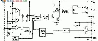
Rice. 3.14. Block diagram of IC IR2153
The electrical circuit diagram of an electronic ballast based on IR2153 is shown in Fig. 3.15.
IR2153
is a high-power insulated gate field-effect transistor (MOSFET) driver with an internal oscillator. It is an exact copy of the generator used in the 555 series timer, the domestic analogue is KR1006VI1. Operates directly from the DC bus through the quenching resistor R1.
Internal voltage regulation prevents Vcc from exceeding 15.6 V. Undervoltage lockout disables both gate drive outputs VT1 and VT2 when Vcc is below 9 V.
DA1 has two control outputs
:
- lower 5 for controlling VT2;
- the top 7 output for controlling VT1, “floating”, since the pulse shaper for controlling the field-effect transistor VT1 is powered from a floating power source, which is formed by elements VD2, C7).
Rice. 3.15. Schematic diagram of an electronic ballast based on IR2153
When managing power keys
(VT1, VT2), the IR2151 chip provides a switching delay of 1.2 μs to prevent a situation where transistors VT1 and VT2 are simultaneously open and through current flows through them, which instantly disables both transistors.
This ballast is designed to power one or two lamps with a power of 40 (36) W (lamp current - 0.43 A) from an alternating current network of 220 V 50 Hz. When using two 40 W lamps, it is necessary to add the elements highlighted in dotted lines (EL2, L3, C11, RK3). It should be noted that for stable operation, the ratings of the elements in parallel branches must be equal (L3, C11 = L2, C10), and the length of the wires connected to the lamps must be the same.
Advice
. When operating one driver for two lamps, it is preferable to use frequency heating of the electrodes (without posistors). This method will be described below (when describing the electronic ballasts on the IR53HD420 chip).
When using lamps of a different power (18-30 W), the ratings should be changed L2 = 1.8-1.5 mH (respectively); when using lamps with a power of 60-80 W - L2 = 1-0.85 mH, and R2 - from the condition of fulfilling F g ~ F b (formulas for calculating these frequencies are given below).
Mains voltage 220 V is supplied to the surge protector
(electromagnetic compatibility filter) formed by elements C1, L1, C2, SZ. The need for its use is due to the fact that key converters are sources of electromagnetic radio frequency interference, which network wires radiate into the surrounding space like antennas.
Current Russian and foreign standards regulate the levels of radio interference generated by these devices. Two-tier LC filters and shielding of the entire structure give good results.
At the input of the network filter, a traditional unit for protection against network surges and impulse noise is included, including a varistor RU1 and a fuse FU1. The negative temperature coefficient (NTC) thermistor RK1 limits the input current surge caused by the charge of the capacitive filter C4 at the inverter input when the electronic ballast is connected to the network.
Next, the network voltage is rectified by the diode bridge VD1 and smoothed by capacitors C4. The R1C5 chain powers the DAI chip - IR2153. The frequency of the internal oscillator FT of the microcircuit is set by the elements R2 = 15 kOhm; C6 = 1 nF according to the formula
The resonant frequency of the ballast circuit F6 is set by the elements L2 = 1.24 mH; C10 = 10 nF according to the formula
To ensure good resonance, the following condition must be met: the frequency of the internal oscillator must be approximately equal to the resonant frequency of the ballast circuit, i.e. Fg ~ Fb.
Construction and details
. The line filter choke L1 is wound on a ferrite ring K32x20x6 M2000NM with a two-core network wire until the window is completely filled. It is possible to replace the power supply of a TV, VCR, or computer with a choke from a PFP.
Good noise suppression results are obtained by specialized EPCOS filters: B8414-D-B30; В8410-В-А14.
The choke of the electronic ballast L2 is made on a W-shaped magnetic core made of M2000NM ferrite. Core size W5x5 with gap 8 = 0.4 mm. The size of the gap in our case is the thickness of the gasket between the contacting surfaces of the halves of the magnetic circuit. It is possible to replace the magnetic core with Ш6x6 with a gap of δ = 0.5 mm; Ш7х7 with gap
δ = 0.8 mm.
To make a gap
it is necessary to lay gaskets made of non-magnetic material (non-foil fiberglass or getinax) of appropriate thickness between the contacting surfaces of the magnetic circuit halves and fasten them with epoxy glue.
The value of the inductance of the inductor (at a constant number of turns) depends on the size of the non-magnetic gap. As the gap decreases, the inductance increases, and as it increases, it decreases. It is not recommended to reduce the gap size, as this leads to saturation of the core.
When the core is saturated, its relative magnetic permeability decreases sharply, which entails a proportional decrease in inductance. A decrease in inductance causes an accelerated increase in current through the inductor and its heating. The current passing through the LL also increases, which negatively affects its service life. The rapidly increasing current through the inductor also causes shock current overloads of power switches VT1, VT2, increased ohmic losses in the switches, their overheating and premature failure.
Winding L2
— 143 turns of PEV-2 wire with a diameter of 0.25 mm.
Interlayer insulation is varnished fabric. Winding - turn to turn. The main dimensions of W-shaped cores
(consisting of two identical W-shaped cores) made of soft magnetic ferrites (according to GOST 18614-79) are given in table. 3.2.
Table 3.2. Main dimensions of W-shaped cores
Transistors VT1, VT2 - IRF720
, high-power field-effect transistors with an insulated gate. MOSFET is Metal Oxide Semiconductor Field Effect Transistor; in the domestic version, MOS PTs are field-effect transistors of the metal-oxide-semiconductor structure.
Let's look at their parameters:
- constant drain current (ID) - 3.3 A;
- pulse drain current (I DM) -13 A;
- maximum drain-source voltage (V DS) - 400 V;
- maximum power dissipation (PD) - 50 W;
- operating temperature range (Tj) - from -55 to +150 °C;
- open resistance -1.8 Ohm;
- total gate charge (QG) - 20 nC;
- input capacitance (C ISS) - 410 pF.
When selecting and replacing transistors
(comparison in Table 3.3) for electronic ballasts,
it should be remembered
that today the number of companies producing field-effect transistors is quite large (IR, STMicro, Toshiba, Fairchild, Infineon, etc.). The range of transistors is constantly expanding, and more advanced ones with improved characteristics are appearing. Parameters that you should pay special attention to:
- constant drain current (ID);
- maximum drain-source voltage (VDS);
- on-state resistance, RDS(on);
- total gate charge (QG);
- input capacitance CISS.
Possible transistor replacements for electronic ballast
: IRF730, IRF820, IRFBC30A (International Rectifier); STP4NC50, STP4NB50, STP6NC50, STP6NB50 (STMicroelectronics); field-effect transistors from Infineon (https:// www.infineon.com) series LightMos, CoolMOS, SPD03N60C3, ILD03E60, STP03NK60Z; PHX3N50E from PHILIPS, etc.
The transistors are installed on small plate radiators. The length of the conductors between driver outputs 5, 7, resistors in the gate circuits R3, R4 and the gates of field-effect transistors should be minimal.
Table 3.3. Comparison table with the parameters of some transistors for electronic ballasts
Rice. 3.16. Main dimensions of the core (to table 3.2)
Diode bridge VD1 - imported RS207; permissible forward current 2 A; reverse voltage 1000 V. Can be replaced with four diodes with the appropriate parameters.
Diode VD2 class ultra-fast (ultra-fast) - reverse voltage of at least 400 V; permissible direct direct current - 1 A; reverse recovery time - 35 ns. Suitable: 11DF4, BYV26B/C/D, HER156, HER157, HER105-HER108, HER205-HER208, SF18, SF28, SF106-SF109, BYT1-600. This diode should be located as close to the chip as possible.
The DAI chip is IR2153, it is replaceable with IR2152, IR2151, IR2153D, IR21531, IR2154, IR2155, L6569, MC2151, MPIC2151. When using the IR2153D, the VD2 diode is not required, since it is installed inside the chip.
Resistors R1-R5 - OMLT or MLT.
Capacitors S1-SZ - K73-17 at 630 V; C4 - electrolytic (imported) with a rated voltage of at least 350 V; C5 - electrolytic at 25 V; C6 - ceramic 50 V; C7 - ceramic or K73-17 for a voltage of at least 60 V; C8, C9 - K73-17 at 400 V; SYU - polypropylene K78-2 for 1600 6.
Varistor RU1 from EPCOS - S14K275, S20K275, replace it with TVR (FNR) 14431, TVR (FNR) 20431 or domestic CH2-1a-430 V.
Thermistor (thermistor) RK1 with negative temperature coefficient (NTC - Negative Temperature Coefficient) - SCK 105 (10 Ohm, 5 A) or from EPCOS - B57234-S10-M, B57364-S100-M.
The thermistor can be replaced with a 4.7 Ohm wirewound resistor with a power of 3-5 W.
The RK2 posistor is a PTC (Positive Temperature Coefficient) thermistor with a positive temperature coefficient. The developers of IR2153 recommend using a posistor from Vishay Cera-Mite - 307C1260. Its main parameters
:
- nominal resistance at +25 °C - 850 Ohm;
- instantaneous (maximum permissible) rms voltage applied to the posistor when the lamp is ignited - 520 V;
- constant (maximum permissible) rms voltage applied to the posistor during normal operation of the lamp, -175 V;
- maximum permissible switching current (transferring the posistor to a high-resistance state) -190 mA;
- the posistor diameter is 7 mm.
A possible replacement for the RK2 posistor is pulse posistors from EPCOS (number of switching cycles 50000-100000): B59339-A1801-P20, B59339-A1501-P20, B59320-J120-A20, B59339-A1321-P20.
PTC resistors with the necessary parameters in quantities sufficient for eight electronic ballasts can be made from the widely used ST15-2-220 PT resistor from the ZUSTST TV demagnetization system. Having disassembled the plastic case, two “tablets” are removed. Using a diamond file, make two cross-cuts on each one, as shown in Fig. 3.17, and break it along the notches into four parts.
Advice
. It is very difficult to solder leads to the metallized surfaces of a posistor made in this way. Therefore, as shown in Fig. 3.18, make a rectangular hole in the printed circuit board (item 3) and clamp a piece of the “tablet” (item 1) between the elastic contacts (item 2) soldered to the printed conductors. By selecting the size of the fragment, you can achieve the desired duration of warming up the lamp.
Rice. 3.17. “Tablet” of a posistor with notches
Rice. 3.18. Mounting a homemade posistor on the board
Advice
. If the fluorescent lamp is intended to be used in infrequent on-off mode, then the posistor can be omitted.
Settings
. The spread of parameters of elements C6, L2, SY may require adjustment of the driver frequency. The easiest way to achieve equality of the frequency of the master oscillator of the IR2153 microcircuit with the resonant frequency of the L2C10 circuit is by selecting the frequency-setting resistor R2. To do this, it is convenient to temporarily replace it with a pair of series-connected resistors: constant (10-12 kOhm) and trimmer (10-15 kOhm). The criterion for correct setting is reliable starting (ignition) and stable burning of the lamp.
The ballast is assembled on a printed circuit board made of foil fiberglass and placed in an aluminum shielding casing. The printed circuit board and the arrangement of elements are shown in Fig. 3.19.
Rice. 3.19. Printed circuit board and arrangement of elements
Hello everybody!
Background:
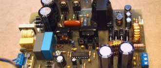
On the site there is a diagram of audio frequency power amplifiers (ULF) 125, 250, 500, 1000 Watt, I chose the 500 Watt option, because in addition to radio electronics, I am also a little interested in music and therefore I wanted something of better quality from ULF. The circuit on the TDA 7293 did not suit me, so I decided on the option of 500 watt field-effect transistors. From the beginning I almost assembled one ULF channel, but work stopped for various reasons (time, money and unavailability of some components). As a result, I bought the missing components and completed one channel. Also, after a certain time, I assembled the second channel, set it all up and tested it on a power supply from another amplifier, everything worked at the highest level and I really liked the quality, I didn’t even expect that it would be like this. Special, huge thanks to radio amateurs Boris, AndReas, Nissan, who throughout the entire time I assembled it, helped in setting it up and in other nuances. Next, it became a matter of the power supply. Of course, I would like to make a power supply on a regular transformer, but again everything stops on the availability of materials for the transformer and their cost. Therefore, I decided to stick with the UPS.
Well, now about the UPS itself:
I used IRFP 460 transistors, since I did not find those indicated on the diagram. I had to install the transistors the other way around, turning them 180 degrees, drill more holes for the legs and solder them together with wires (you can see it in the photo). When I made the printed circuit board, I only realized later that I couldn’t find the transistors I needed as in the diagram, so I installed the ones I had (IRFP 460). Transistors and output rectifier diodes must be installed on a heat sink through heat-insulating gaskets, and the radiators must also be cooled with a cooler, otherwise the transistors and rectifier diodes may overheat, but the heating of the transistors, of course, also depends on the type of transistors used. The lower the internal resistance of the field switch, the less it will heat up.
Also, I have not yet installed a 275 Volt Varistor at the input, since it is not in the city and neither is mine, and it is expensive to order one part via the Internet. I will have separate electrolytes at the output, because they are not available for the required voltage and the standard size is not suitable. I decided to put 4 electrolytes of 10,000 microfarads * 50 volts, 2 in series in the arm, in total in each arm it will be 5000 microfarads * 100 volts, which will be completely enough for the power supply, but it is better to put 10,000 microfarads * 100 volts in the shoulder.
The diagram shows a resistor R5 47 kOhm 2 W for powering the microcircuit, it should be replaced with 30 kOhm 5 W (preferably 10 W) so that under a heavy load, the IR2153 microcircuit has enough current, otherwise it may go into protection against a lack of current or will pulsate tension which will affect the quality. In the author’s circuit it is 47 kOhm, which is a lot for such a power supply. By the way, resistor R5 will heat up very much, don’t worry, the type of circuits with IR2151, IR2153, IR2155 power supply is accompanied by strong heating of R5.
In my case, I used an ETD 49 ferrite core and it fit very hard on the board. At a frequency of 56 KHz, according to calculations, it can deliver up to 1400 watts at this frequency, which in my case has a margin. You can use a toroidal or other shaped core, the main thing is that it is suitable in terms of overall power, permeability and, of course, there is enough space to place it on the board.
Winding data for ETD 49: 1 = 20 turns with 0.63 V wire 5 wires (winding 220 volts). 2 = main power bipolar 2*11 turns of 0.63 V wire 4 wires (winding 2*75-80) volts. 3 = 2.5 turns of wire 0.63 in 1 wire (winding 12 volts, for soft start). 4 = 2 turns of wire 0.63 in 1 wire (additional winding for powering preliminary circuits (tone block, etc.). The transformer frame needs a vertical design, I have a horizontal one, so I had to fence it. It can be wound in a frameless design. On other types you will have to calculate the core yourself, you can use the program that I will leave at the end of the article.In my case, I used a bipolar voltage of 2 * 75-80 volts for a 500 watt amplifier, why less, because the amplifier load will not be 8 Ohms but 4 Ohms.
Setup and first launch:
When starting the UPS for the first time, be sure to install a 60-100 watt light bulb in the gap between the network cable and the UPS. When you turn it on, if the light does not light, then it’s good. At the first start-up, short-circuit protection may turn on and the HL1 LED will light up, since the electrolytes have a large capacity and take a huge current at the moment of switching on. If this happens, then you need to twist the multi-turn resistor clockwise until it stops, and then wait until the LED goes out off state and try to turn it on again to make sure the UPS is working, and then adjust the protection. If everything is soldered correctly and the correct part ratings are used, the UPS will start. Next, when you have made sure that the UPS turns on and there is all voltage at the output, you need to set the protection threshold. When setting up protection, be sure to load the UPS between the two arms of the main output winding (which is used to power the ULF) with a 100-watt light bulb. When the HL1 LED lights up when turning on the UPS under load (100-watt light bulb), you need to turn the variable multi-turn resistor R9 2.2 kOhm a little counterclockwise until the power-on protection is triggered. When the LED lights up when you turn it on, you need to turn it off and wait until it goes out and gradually turn it clockwise in the off state and turn it on again until the protection stops working, you just need to turn it a little, for example 1 turn and not immediately by 5-10 turns, those. turned it off, tweaked it and turned it on, the protection worked - again the same procedure several times until you achieve the desired result. When you set the required threshold, then, in principle, the power supply is ready for use and you can remove the mains voltage light and try to load the power supply with an active load, for example, 500 watts. Of course, you can play around with the protection as you like, but I don’t recommend doing tests with Short circuit, since this can lead to a malfunction, even though there is protection, some capacity will not have time to discharge, the relay will not respond instantly or will stick and there may be trouble. Although I accidentally and not accidentally made a number of short circuits, the protection works. But nothing is eternal.
Measurements after UPS assembly:
Measurements between arms: U in - 225 volts, load - 100 watts, U out +- = 164 volts U in - 225 volts, load - 500 watts, U out +- = 149 volts U in - 225 volts, load - 834 watts , U out +- = 146 volts
Of course there is subsidence. With a load of 834 watts before the input rectifier, the voltage sags from 225 volts to 220 volts, after the rectifier it sags by as much as 20 volts from 304 volts to 284 volts with a load of 834 watts. But in principle, the output sag on each arm is 9 volts, which is in principle acceptable, since the UPS is not stabilized.
Thanks everyone for your attention.
So the first power supply, let’s call it “high-voltage”:
The circuit is classic for my switching power supplies. The driver is powered directly from the network through a resistor, which reduces the power dissipated by this resistor compared to power supply from the +310V bus. This power supply has a soft start (inrush current limiting) circuit on the relay. Soft start is powered through quenching capacitor C2 from a 230V network. This power supply is equipped with protection against short circuit and overload in secondary circuits. The current sensor in it is resistor R11, and the current at which the protection is triggered is regulated by trimming resistor R10. When the protection is triggered, the HL1 LED lights up. This power supply can provide a bipolar output voltage of up to +/-70V (with these diodes in the secondary circuit of the power supply). The pulse transformer of the power supply has one primary winding of 50 turns and four identical secondary windings of 23 turns each. The wire cross-section and transformer core are selected based on the required power that must be obtained from a particular power supply.
The second power supply, we will conventionally call it a “self-powered UPS”:
This unit has a circuit similar to the previous power supply, but the fundamental difference from the previous power supply is that in this circuit, the driver powers itself from a separate winding of the transformer through a quenching resistor. The remaining nodes of the circuit are identical to the previous presented circuit. The output power and output voltage of this unit is limited not only by the parameters of the transformer and the capabilities of the IR2153 driver, but also by the capabilities of the diodes used in the secondary circuit of the power supply. In my case it is KD213A. With these diodes, the output voltage cannot be more than 90V, and the output current cannot be more than 2-3A. The output current can be higher only if radiators are used to cool the KD213A diodes. It is worth additionally stopping at the T2 throttle. This inductor is wound on a common ring core (other types of cores can also be used), with a wire of a cross-section corresponding to the output current. The transformer, as in the previous case, is calculated for the appropriate power using specialized computer programs.
Power supply number three, let’s call it “powerful with 460 transistors” or simply “powerful 460”:
This scheme is already more significantly different from the previous schemes presented above. There are two main big differences: protection against short circuit and overload here is made on a current transformer, the second difference is the presence of two additional transistors in front of the keys, which allow isolating the high input capacitance of powerful switches (IRFP460) from the driver output. Another small and insignificant difference is that the limiting resistor of the soft start circuit is located not in the +310V bus, as was the case in previous circuits, but in the 230V primary circuit. The circuit also contains a snubber connected in parallel with the primary winding of the pulse transformer to improve the quality of the power supply. As in previous schemes, the sensitivity of the protection is regulated by a trimming resistor (in this case R12), and the activation of the protection is signaled by the HL1 LED. The current transformer is wound on any small core that you have at hand, the secondary windings are wound with a wire of small diameter 0.2-0.3 mm, two windings of 50 turns each, and the primary winding is one turn of wire of a cross-section sufficient for your output power.
And the last pulse generator for today is a “switching power supply for light bulbs,” let’s call it that.
Yes yes, don't be surprised. One day there was a need to assemble a guitar preamplifier, but I didn’t have the necessary transformer at hand, and then this impulse generator, which was built just for that occasion, really helped me out. The scheme differs from the previous three in its maximum simplicity. The circuit does not have protection against short circuits in the load as such, but there is no need for such protection in this case, since the output current on the secondary +260V bus is limited by resistor R6, and the output current on the secondary +5V bus is limited by the internal overload protection circuit of the stabilizer 7805. R1 limits the maximum starting current and helps cut off network noise.
8.2 kOhm
Switching power supply for IR2151-IR2153
The advantage of any switching power supply is that there is no need to wind or buy a bulky transformer. All you need is a transformer with several turns. This power supply
to make yourself
and requires few parts.
And the basis is that the power supply is based on the IR2151 chip.
A characteristic feature of this power supply is its simplicity and repeatability. The circuit contains a small number of components and has proven itself for more than two years. A standard step-down transformer from a computer power supply is used as a pulse transformer.
There is a PTC thermistor at the input
– a semiconductor resistor with a positive temperature coefficient, which sharply increases its resistance when a certain characteristic temperature TRef is exceeded.
Protects power switches at the moment of switching on while capacitors are charging. Diode bridge
at the input for rectifying the mains voltage to a current of 10A.
A “vertical” type diode assembly was used, but a “stool” type diode assembly can be used. A pair of capacitors
at the input is taken at the rate of 1 microfarad per 1 W.
In our case, the capacitors will “pull” a load of 220W. The damping resistance in the driver power circuit is 2 W. Preference is given to domestic resistors of the MLT-2 type. Driver IR2151
– for controlling the gates of field-effect transistors operating under voltages up to 600V.
Possible replacement for IR2152, IR2153. If the name contains the index “D”, for example IR2153D, then the FR107 diode in the driver harness is not needed. The driver alternately opens the gates of the field-effect transistors with a frequency set by the elements on the legs Rt and Ct. Field effect transistors
are preferably used from IR. Select a voltage of at least 400V and with minimal open resistance. The lower the resistance, the lower the heating and the higher the efficiency. We can recommend IRF740, IRF840, etc. A reference book on field-effect transistors from IR in Russian can be downloaded here. Attention! Do not short-circuit the flanges of field-effect transistors; When installing on a radiator, use insulating gaskets and bushing washers. A standard step-down transformer from a computer power supply. As a rule, the pinout corresponds to that shown in the diagram. Homemade transformers wound on ferrite tori also work in this circuit. Homemade transformers are calculated for a conversion frequency of 100 kHz and half the rectified voltage (310/2 = 155V). When choosing a transformer, you should choose one whose pins on the original board are short-circuited as shown in the diagram. It is important. Otherwise, you should close it as it was done on the board from which you are removing the transformer. Output diodes with a recovery time of no more than 100 ns. These requirements are met by diodes from the HER (High Efficiency Rectifier) family. Not to be confused with Schottky diodes. The output capacity is a buffer capacity. Do not install a capacitance of more than 10,000 microfarads.
Printed circuit board
Practice has shown that this application does not require a special organization of feedback, inductive power supply filters, snubbers and other “bells and whistles” inherent in pulse converters. One way or another, the typical defects characteristic of “poor nutrition” (background and extraneous sounds) are not felt in the sound. Field-effect transistors do not get very hot during operation.
Passive cooling is sufficient for them. IR field-effect transistors are very resistant to thermal destruction and operate up to temperatures of 150? C. But this does not mean that they should be operated in such a critical mode. For such cases, you will need to organize active cooling, or, simply, install a fan.
Like any device, this power supply requires careful and careful assembly, correct installation of polar elements and caution when working with mains voltage. After turning off this power supply, no dangerous voltage remains in its circuits. A properly assembled power supply does not require configuration or adjustment.
Switching amplifier power supply for IR2151-IR2153
The characteristic feature of this power supply is its simplicity and repeatability. The circuit contains a small number of components and has proven itself for more than two years. A standard step-down transformer from a computer power supply is used as a pulse transformer.
At the input there is a PTC thermistor (Positive Temperature Coefficient) - a semiconductor resistor with a positive temperature coefficient, which sharply increases its resistance when a certain characteristic temperature TRef is exceeded. Protects power switches at the moment of switching on while capacitors are charging.
Diode bridge at the input for rectifying the mains voltage to a current of 10A. A “vertical” type diode assembly was used, but a “stool” type diode assembly can be used.
A pair of capacitors at the input is taken at the rate of 1 microfarad per 1 W. In our case, the capacitors will “pull” a load of 220W.
The damping resistance in the driver power circuit is 2 W. Preference is given to domestic resistors of the MLT-2 type.
Driver IR2151 – for controlling the gates of field-effect transistors operating under voltages up to 600V. Possible replacement for IR2152, IR2153. If the name contains the index “D”, for example IR2153D, then the FR107 diode in the driver harness is not needed. The driver alternately opens the gates of the field-effect transistors with a frequency set by the elements on the legs Rt and Ct.
Field effect transistors are preferably used from IR (International Rectifier). Select a voltage of at least 400V and with minimal open resistance. The lower the resistance, the lower the heating and the higher the efficiency. We can recommend IRF740, IRF840, etc. A reference book on field-effect transistors from IR in Russian can be downloaded here. Attention! Do not short-circuit the flanges of field-effect transistors; When installing on a radiator, use insulating gaskets and bushing washers.
A standard step-down transformer from a computer power supply. As a rule, the pinout corresponds to that shown in the diagram. Homemade transformers wound on ferrite tori also work in this circuit. Homemade transformers are calculated for a conversion frequency of 100 kHz and half the rectified voltage (310/2 = 155V).
When choosing a transformer, you should choose one whose pins on the original board are short-circuited as shown in the diagram. It is important. Otherwise, you should close it as it was done on the board from which you are removing the transformer.
Output diodes with a recovery time of no more than 100 ns. These requirements are met by diodes from the HER (High Efficiency Rectifier) family. Not to be confused with Schottky diodes.
The output capacity is a buffer capacity. Do not abuse and install a capacitance of more than 10,000 microfarads.
Below is a drawing of the printed circuit board.
Practice has shown that this application does not require a special organization of feedback, inductive power supply filters, snubbers and other “bells and whistles” inherent in pulse converters. One way or another, the typical defects characteristic of “poor nutrition” (background and extraneous sounds) are not felt in the sound.
Field-effect transistors do not get very hot during operation. Passive cooling is sufficient for them. IR field-effect transistors are very resistant to thermal destruction and operate up to temperatures of 150? C. But this does not mean that they should be operated in such a critical mode. For such cases, you will need to organize active cooling, or, simply, install a fan.
Below is a photo of the assembled power supply.
Like any device, this power supply requires careful and careful assembly, correct installation of polar elements and caution when working with mains voltage. After turning off this power supply, no dangerous voltage remains in its circuits. A properly assembled power supply does not require configuration or adjustment.
Additional files (PCB, switching power supply transformer calculation program) can be downloaded from the following links:
Author: Timofey Nosov
You might be interested in this:
meandr.org
Details and design
The filter choke for the 220 Volt power supply (Dr1) was taken from a switching power supply from a TV; any one will do, taking into account the amount of power you want to receive... Varistor - any 10 ohm, but not from a phone charger and similar low-power switching power supplies.
The inductance of 25 Volts (L) was taken from a 450-watt computer power supply, the extra windings were wound up - we leave only those wound with a thick wire.
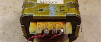
The high-frequency transformer Tr1 was taken from the same place; I will dwell in detail on its winding from scratch. It is quite difficult to disassemble such a transformer without splitting the ferrite. To simplify the task, you need to put it on the stove and heat it to a hundred degrees, in other words, as soon as a drop of water on the ferrite boils, you can disassemble it.
With this heating, the glue becomes soft and the ferrite halves are easily pulled out of the frame with the winding. When winding transformers in pulse circuits, it is recommended to wind the windings with several wires - up to 8 pieces at a time.
It is not at all necessary to do this; I wound the primary winding with one enameled copper wire with a diameter of 0.45 mm - 49 turns. Secondary windings II and III were wound with two wires with a diameter of 0.8 mm - 8 turns each.
We use high-speed rectifier diodes - KD213 or KD212 are suitable from domestic ones. For the latter, the load current according to the reference book is 1A, and for KD213 it is 10A. Diodes with a limit operating frequency of 100 kHz are suitable.
Instead of the IRF740 transistor, you can use the IRF840 and the like. The radiator for the transistors can be installed at half the size; under full, long-term load, the transistors do not heat up very much - 45 degrees to the touch. Transistors must be placed on the radiator through insulating gaskets.
Instead of RL205 diodes, you can install any diode bridge with a maximum constant reverse voltage of 600V and a maximum constant forward current of 6A.
The transition capacitance (0.1 µF) between the transistors and the transformer must be for a voltage of 630V!
With the specified ratings, this circuit provides an output power of approximately 200 W at a current of up to 4.5A.
I didn’t make a signet for the power supply circuit; I just drew it on the PCB. Each part and their location options may be different. The diagram is simple and drawing your own signet will not be difficult.
Here's what I got:
Rice. 3. Plan of my printed circuit board for a switching network power supply.
As you can see from the sketch, instead of a separating capacitor between the transistors and the transformer, I have three pieces installed. I had to do this because there wasn’t one for the required voltage, so I ended up collecting it from different capacitors with a total capacitance of 0.5 µF.
The most ideal option would be 1 µF at 630V. But everything works quite normally with both a 0.1 µF capacitance and a 0.5 µF capacitance.
Rice. 4. Finished printed circuit board for a switching power supply (view from the connections side).
Rice. 5. Finished switching power supply board (view from the parts side).
Rice. 6. Homemade network switching power supply for UMZCH.
Rice. 7. Appearance of a network switching power supply for a low-frequency power amplifier.
IR2153 - microcircuit parameters, datasheet and power supply circuits
Based on the IR2153 chip and power IGBT transistors, many circuits have been designed, such as an induction heater driver and generator, a Tesla coil power supply, DC-DC converters, switching power supplies, and so on. And the NGTB40N120FL2WG + IR2153 combination works perfectly together, where IR2153 is the driver - the master pulse generator, and a pair of 40A/1000V insulated gate bipolar transistors can handle a large load current.
IR2153 connection diagrams
Schematic diagram of IR2153 connection
IR2153 - power supply electrical circuit
Tesla circuit on IR2153
If you are going to repeat one of these circuits, here is an archive with printed circuit board files. The gate pulse generator circuit for their control operates from 15 V DC - up to 400 V voltage is supplied to the transistors of the output stage.
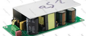
IR2153 switching power supply on board
By the way, the IR2153 is an improved version of the popular IR2155 and IR2151, which includes a high-voltage half-bridge gate driver. The IR2153 provides more features and is easier to use than previous m/s. There is a shutdown feature so that both gate driver outputs can be turned off using a low signal voltage. Noise immunity has been significantly improved, both by reducing peak pulses. Finally, special attention has been paid to providing as comprehensive ESD protection as possible on all terminals.
Features of power supply on IR2153
- Load power supply from 60 to 400 V DC
- Driver supply voltage 15 V DC
- Generation frequencies 12 kHz - 100 kHz
- Duty ratio approximately 50%
- Manual potentiometer for setting frequencies
Technical characteristics of microcircuits and transistors
| CHIP | Maximum Driver Voltage | Start supply voltage | Stop supply voltage | Maximum power transistor gate charging current/rise time | Maximum power transistor gate discharge current/fall time | Internal Zener diode voltage |
| IR2151 | 600 V | 7.7…9.2 V | 7.4…8.9 V | 100 mA / 80…120 nS | 210 mA / 40…70 nS | 14.4…16.8 V |
| IR2153 | 600 V | 8.1…9.9 V | 7.2…8.8 V | NOT SPECIFIED / 80…150 nS | NOT SPECIFIED / 45…100 nS | 14.4…16.8 V |
| IR2155 | 600 V | 7.7…9.2 V | 7.4…8.1 V | 210 mA / 80…120 nS | 420 mA / 40…70 nS | 14.4…16.8 V |
| TRANSISTORS FOR PULSE PSUs | |||||||
| NAME | E.g. | CURRENT | SOPR. | POWER | GATE CAPACITY | Qg (PRODUCT) | |
| NETWORK (220 V) | |||||||
| IRFBC30 | 600V | 3.6A | 1.8 Ω | 100W | 660pF | 17…23nC (ST ) | |
| IRFBC40 | 600V | 6.2A | 1 Ω | 125W | 1300pF | 38…50nC (ST ) | |
| IRF740 | 400V | 10A | 0.48 Ω | 125W | 1400pF | 35…40nC (ST ) | |
| IRF840 | 500V | 8A | 0.85 Ω | 125W | 1300pF | 39…50nC (ST ) | |
| STP8NK80Z | 800V | 6A | 1.3 Ω | 140W | 1300pF | 46nC (ST ) | |
| STP10NK60Z | 600V | 10A | 0.75 Ω | 115W | 1370pF | 50…70nC (ST ) | |
| STP14NK60Z | 600V | 13A | 0.5 Ω | 160W | 2220pF | 75nC (ST ) | |
| STP25NM50N | 550V | 22A | 0.14 Ω | 160W | 2570pF | 84nC (ST ) | |
| IRFB18N50K | 500V | 17A | 0.26 Ω | 220W | 2830pF | 120nC (IR) | |
| SPA20N60C3 | 650V | 20A | 0.19 Ω | 200W | 2400pF | 87…114nC (IN) | |
| STP17NK40Z | 400V | 15A | 0.25 Ω | 150W | 1900pF | 65nC (ST ) | |
| STP8NK80ZFP | 800V | 6A | 1.3 Ω | 30W | 1300pF | 46nC (ST ) | |
| STP10NK60FP | 600V | 10A | 0.19 Ω | 35W | 1370pF | 50…70nC (ST ) | |
| STP14NK60FP | 600V | 13A | 0.5 Ω | 160W | 2220pF | 75nC (ST ) | |
| STP17NK40FP | 400V | 15A | 0.25 Ω | 150W | 1900pF | 65nC (ST ) | |
| STP20NM60FP | 600V | 20A | 0.29 Ω | 45W | 1500pF | 54nC (ST ) | |
| IRFP22N60K | 600V | 22A | 0.24 Ω | 370W | 3570pF | 150nC(IR) | |
| IRFP32N50K | 500V | 32A | 0.135 Ω | 460W | 5280pF | 190nC(IR) | |
| IRFPS37N50A | 500V | 36A | 0.13 Ω | 446W | 5579pF | 180nC(IR) | |
| IRFPS43N50K | 500V | 47A | 0.078 Ω | 540W | 8310pF | 350nC(IR) | |
| IRFP450 | 500V | 14A | 0.33 Ω | 190W | 2600pF | 150nC (IR) 75nC (ST ) | |
| IRFP360 | 400V | 23A | 0.2 Ω | 250W | 4000pF | 210nC(IR) | |
| IRFP460 | 500V | 20A | 0.27 Ω | 280W | 4200pF | 210nC(IR) | |
| SPW20N60C3 | 650V | 20A | 0.19 Ω | 200W | 2400pF | 87…114nC (IN) | |
| SPW35N60C3 | 650V | 34A | 0.1 Ω | 310W | 4500pF | 150…200nC (IN) | |
| SPW47N60C3 | 650V | 47A | 0.07 Ω | 415W | 6800pF | 252…320nC (IN) | |
| STW45NM50 | 550V | 45A | 0.1 Ω | 417W | 3700pF | 87…117nC (ST) | |
Possible changes
The oscillator frequency is controlled by a potentiometer and covers the range from 10 kHz to 100 kHz, duty cycle 50%.
Ready power supply for IR2153
Naturally, other MOSFETs or IGBTs can be used in the above circuits. Don't forget that transistors require a large heatsink. You can download the datasheet for IR2153 using the link.
2shemi.ru
Fluorescent lamp ballast parts
Electrolytic capacitors type K50-68, non-polar - K10-17b, K73-17. The minimum voltage of capacitor C5 must be at least 400 V. The VD5 diode must be of the ultra-fast type designed for a reverse voltage of at least 400 V. They can be the following diodes: BYV26D, 11DF4, BYV26C, BYV26B, HER156, HER157, HER105, SF28, HER205, HER106, HER206, SF106. The IR2151 chip can be replaced with IR2153, IR2152, IR2155.
It is possible to replace transistors: KP728, KP726, IRF730, IRF740, IRF840, KP770D, KP751A. Thermistor R7 can be replaced with B59339-A1801-P20 or B59339-A1501-P20, B59320-J120-A20. Although sometimes this thermistor can be excluded from the circuit. To do this, try starting the lamp without a thermistor. If it turns on confidently, without multiple flashes, then the thermistor does not need to be installed.
Simple and affordable switching power supply for IR2151, IR2152, IR2153 200W
When assembling some new device, the question of how to power it is increasingly tormented. Yes, it’s good when there is a lot of different equipment where there are suitable transformers, but what if you rewind??? Rewinding a transformer is not a pleasant task, even if applications for calculating a transformer help with the calculations, the rewinding process itself is often annoying.
I remember once there was a TSSh-180, a good anode-hot trans, and I had to rewind it. I probably wound it for two days, plus I sprayed it with varnish so that the insulation would be better and it wouldn’t make a buzzing sound... I assembled it, it’s so healthy. I weighed 3 kg and almost fell on my leg. I thought about all this and decided to switch to switching power supplies and there are a lot of reasons for this. Reasons for choosing switching power supplies:
1. The first and no less important reason is financial. Here we have the same TSH-180 a.-incandescent costs 150-180 UAH. While a 200W SMPS on an IR2153 assembly will cost 130-160 UAH. Yes, the difference is not great, but your home is full of the necessary parts. For example, I only purchased IRF740 and IR2153 and paid 40 UAH. What's the difference?? And I also got rid of a little junk)) And we also remember that the bridge and banks are already included in the calculation, and this also needs to be bought for the trance. And good jars cost so much. And on the SMPS instead of 22,000mF, you can put 3300mF and you won’t even notice the difference in filtering
2. The second reason is the size. The trances are heavy, 200 watts weighing 3-4 kg, replaced by an SMPS weighing 300g and a board size of about 120*120mm. It’s convenient to collect something powerful in a DVD box, Lanzar for example...
3. This is a low level of interference within the range of 20-20,000Hz. This is very good for a bass amplifier, even great. No interference, no background.
I won’t torture you further, here is the SMPS diagram for IR2151, IR2152, IR2153 divided into 3 parts:
1. Power IR2151, IR2152, IR2153
In the diagram we see the power part, which contains: protective circuits (R1, R2, FU1), CRC filter (C1, L1, C1), rectifier with filter divider (VD1 (400V 3A), C3, C4, C6, C7, R44, R6) and a key part which includes two mosfets (VT1, VT2), a transformer (T1) and two interference suppression circuits (R8C9, C8R7)
2. Control part IR2151, IR2152, IR2153
There is nothing complicated in the control part either. The power supply part of the microcircuit consists of a ballast resistor R9 and a zener diode VD2. filter C10C11, and another ballast resistor R10. During the work you may have to pick up R9R10. The PWM operating frequency is set by R11C13. And it is calculated using the formula f=1/1.4*(R11+75Ohm)*C13. In our case, it turns out f=1/1.4*(10000+75)*0.000000001=70896 Hz= 70.9 kHz. Be careful with zeros
3. Rectifying part of the secondary circuits on the SMPS IR2151, IR2152, IR2153
Well, there’s really nothing to tell here: Dual diode VD4, filter rectifier C14-L3-C15-C16 and that’s it. Remember when calculating that this is not a stabilized power supply and the voltage may fluctuate. Therefore, it is better to enter a couple of volts less when calculating
When calculating a transformer, the application for calculating Pulse Transformers will help you. The advice is to wind the secondary with a slant of thinner wire in order to avoid the skin effect.
By the way, one of my friends uses such a circuit to power 2.1 units assembled on a TDA2030A with a total power of 65W. This is a small part of what the SMPS produces on IR2153, but it works for years. Yes, again, a 70W transformer now costs the same as the SMPS unit on IR2153, so the SMPS also has a reserve of 130W...
That's all, thank you all for your attention and good luck with the assembly...
Loading…
Useful materials on this topic:
Post navigation
rustaste.ru
Fluorescent lamp ballast choke
- First option: ferrite grade 2500NMS1 with dimensions W 5x5 with a gap of 0.2 mm. The winding is made of PEV-2 wire with a diameter of 0.2 mm and contains 100 turns.
- Second option: ferrite grade 2000NM having a size W 6x6 with a gap of 0.25 mm. The winding is made of PEV-2 wire with a diameter of 0.2 mm and contains 135 turns.
Fluorescent lamps can be powered not only from a 220 volt network, but also from powerful stationary power sources, for example, powering a fluorescent lamp from 12 volts.
Switching amplifier power supply for IR2151, IR2153
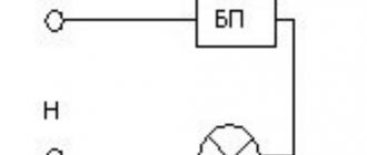
Power supply
Home Radio amateur Power supply
Switching power supplies are the most efficient class of secondary power supplies. They are characterized by compact size, high reliability and efficiency. The only disadvantages include the creation of high-frequency interference and the complexity of design/implementation.
All pulse power banks are a kind of inverters (systems that generate alternating voltage at the high-frequency output from the rectified voltage at the input). The complexity of such systems is not even in first rectifying the input mains voltage, or subsequently converting the output high-frequency signal into a constant one, but in the feedback, which allows you to effectively stabilize the output voltage.
Particularly complex here is the process of controlling high-level output voltages. Very often the control unit is powered from low voltage, which creates the need to coordinate levels.
Drivers IR2151, IR2153
In order to control independently (or dependently, but with a special pause that prevents simultaneous opening of the keys) the channels of the upper and lower keys, self-clocked half-bridge drivers are used, such as IR2151 or IR2153 (the latter chip is an improved version of the original IR2151, both are interchangeable).
There are numerous modifications of these circuits and analogues from other manufacturers.
A typical driver circuit with transistors looks like this.
Rice. 1. Driver connection circuit with transistors
The package type can be PDIP or SOIC (the difference is in the picture below).
Rice. 2. Package type PDIP and SOIC
The modification with the letter D at the end assumes the presence of an additional boost diode.
The differences between the IR2151 / 2153 / 2155 microcircuits in parameters can be seen in the table below.
Table
UPS on IR2153 - the simplest option
The schematic diagram itself looks like this.
Rice. 3. Schematic diagram of the UPS
At the output, you can get bipolar power (implemented by rectifiers with a midpoint).
The power of the power supply can be increased by changing the capacitance parameters of capacitor C3 (calculated as 1:1 - 1 µF is required for 1 W of load).
In theory, the output power can be increased to 1.5 kW (although capacitors of such a capacity will require a soft start system).
With the configuration indicated in the circuit diagram, an output current of 3.3A (up to 511 V) is achieved when used in power amplifiers, or 2.5A (387 V) when connecting a constant load.
UPS with overload protection
The scheme itself.
Rice. 4. UPS circuit with overload protection
This power supply provides a system for switching to the operating frequency, eliminating inrush current surges (soft start), as well as simple protection against RF interference (at the input and output of the inductor).
UPS up to 1.5 kW
The circuit below can handle high-power power transistors such as SPW35N60C3, IRFP460, etc.
Rice. 5. UPS diagram with power up to 1.5 kW
Powerful VT4 and VT5 are controlled through emitter followers on VT2 and VT1.
Amplifier power supply on a transformer from a computer power supply
It often happens that there is practically no need to buy components; they can sit and gather dust as part of equipment that has not been used for a long time, for example, in a PC system unit somewhere in the basement or on the balcony.
Below is one of the fairly simple, but no less efficient UPS circuits for an amplifier.
Rice. 6. UPS circuit for amplifier
An example of a finished printed circuit board might look like this.
Rice. 7. Device circuit board
And a fully realized node is like this.
Rice. 8. Appearance of the device
Author: RadioRadar
Date of publication: 04/09/2018
Readers' opinions
- Andrey / 07/20/2019 — 18:26 Is there voltage stabilization through feedback in the circuit in Figure 4?
- Alexander / 04.24.2019 — 08:24 in Fig. 6 error there is no capacitor in the output transformer circuit
You can leave your comment, opinion or question on the above material:
www.radioradar.net
Description of ballast for fluorescent lamp
The ballast for a fluorescent lamp on IR2151 given in this article is intended for connecting a T12 or T8 type fluorescent lamp with a power of 40 W.
The specialized microcircuit IR2151 is taken as the basis. The ballast is built according to a half-bridge converter circuit with a midpoint defined by capacitors C6 and C7.
A bridge built on diodes VD1-VD4 rectifies the input voltage from the mains, which is then smoothed out by capacitors C6 and C7. Resistor R1 is designed to reduce the inrush current. The pulse generator located inside the IR2151 chip is similar to the generator found in the famous NE555 timer.
Formula for calculating the frequency of the internal oscillator:
Formula for calculating the resonant frequency:
Laboratory power supply 30 V / 10 A
More details
For greater efficiency of the fluorescent lamp ballast, it is necessary that the frequency of the internal generator and the resonant frequency be approximately equal. With the component ratings indicated in the diagram, the resonant frequency is approximately 40 kHz.
The IR2151 microcircuit is powered through elements R2 and C1. The circuit of elements R6, C5 is a snubber that prevents the failure of the IR2151 output stages due to parasitic high-frequency oscillations.
www.teleradiocom.ru - Website for repair of television and radio equipment
| !!! !!! !!! | |||
| <Radiotelephones: | Thanks for visiting this site! The site is dedicated to the repair and operation of electronic devices. It all started with radiotelephones, here are diagrams and instructions for both “Chinese” radiotelephones (Nokia 6150CID, 6110CID and the like), as well as well-known radiotelephones from traditional manufacturers (Harvest, Senao). By following the codes link you can get information on how to register the handset on the base unit of the radiotelephone (about 40 models). Antennas - materials on Rothhammel and magazines. A lot of related material (cables, calculations, everyone’s favorite DX60). Next to it is the famous program for modeling antennas on the MMANA computer by Igor Goncharenko. There are 96 circuit diagrams in the TV section. Articles are devoted to electronics, for beginners, and more. The articles contain many interesting diagrams and calculations. The directory contains typical circuit diagrams for connecting microcircuits and their electrical parameters. | ||
| Instructions | |||
| Scheme | |||
| Office r/tel. | |||
| Codes | |||
| Repair | |||
| <Cell phones | |||
| <Radio stations | |||
| <Antennas | |||
| Scheme: | |||
| Household appliance | |||
| TVs | |||
| TV repair | |||
| <Articles | |||
| <Reference books | |||
| <Forum | |||
| <Your letters | |||
| <Links | |||
| <Site search | |||
| <Electronics news | |||
| <Site news | |||
| <To the webmaster | |||
| <Removable panels | |||
| <Discussions | |||
| <Yulin website | |||
| <Catalogue | |||
| | | | | | | |||
| | | | | | |||
electronix.org.ru
www.teleradiocom.ru - Website for repair of television and radio equipment
| !!! !!! !!! | |||
| <Radiotelephones: | Thanks for visiting this site! The site is dedicated to the repair and operation of electronic devices. It all started with radiotelephones, here are diagrams and instructions for both “Chinese” radiotelephones (Nokia 6150CID, 6110CID and the like), as well as well-known radiotelephones from traditional manufacturers (Harvest, Senao). By following the codes link you can get information on how to register the handset on the base unit of the radiotelephone (about 40 models). Antennas - materials on Rothhammel and magazines. A lot of related material (cables, calculations, everyone’s favorite DX60). Next to it is the famous program for modeling antennas on the MMANA computer by Igor Goncharenko. There are 96 circuit diagrams in the TV section. Articles are devoted to electronics, for beginners, and more. The articles contain many interesting diagrams and calculations. The directory contains typical circuit diagrams for connecting microcircuits and their electrical parameters. | ||
| Instructions | |||
| Scheme | |||
| Office r/tel. | |||
| Codes | |||
| Repair | |||
| <Cell phones | |||
| <Radio stations | |||
| <Antennas | |||
| Scheme: | |||
| Household appliance | |||
| TVs | |||
| TV repair | |||
| <Articles | |||
| <Reference books | |||
| <Forum | |||
| <Your letters | |||
| <Links | |||
| <Site search | |||
| <Electronics news | |||
| <Site news | |||
| <To the webmaster | |||
| <Removable panels | |||
| <Discussions | |||
| <Yulin website | |||
| <Catalogue | |||
| | | | | | | |||
| | | | | | |||
www.electroscheme.ru