Structural scheme
The figure below shows the circuit diagram of channel 1:
As can be seen from the diagram, the amplifier has three inputs, one of which provides a simple possibility of adding a preamplifier-corrector for a vinyl player (if necessary), an input switch, a pre-amplifier-timbre lock (also three-band, with adjustable HF/MF/LF levels), volume control, filter block for three bands with adjustment of the gain level of each band with the ability to disable filtering and a power supply for high-power final amplifiers (unstabilized) and a stabilizer for the “low-current” part (preliminary amplification stages).
Stereo amplifier 12 dB
The TDA8199 can be used with both electronic volume controls and simple potentiometers of the appropriate sound class.
Characteristics
| Supply voltage Upit | 10.8 - 13.2 V |
| Current consumption Ipotr | 21 - 28 mA |
| Gain output/input | 12 dB |
| Audio input impedance Rin | 22 - 1000 Ohm |
| Harmonic coefficient Kr | 0,35 — 1 % |
| Audio output impedance Rout | 30 - 1000 Ohm |
| Output noise voltage Uout noise | 30 µV |
Chip Limits
| Supply voltage Upit | 16 V |
| Working temperature Trab | -55…+125 °C |
| Storage temperature | 0…+70 °C |
Pre-amplifier-timbre block
A circuit that had been tested more than once before was used, which, despite its simplicity and availability of parts, shows quite good characteristics. The diagram (like all subsequent ones) was once published in the magazine “Radio” and then published more than once on various sites on the Internet:
The input stage on DA1 contains a gain level switch (-10; 0; +10 dB), which simplifies the matching of the entire amplifier with signal sources of different levels, and the tone control is directly assembled on DA2. The circuit is not capricious to some variation in the values of the elements and does not require any adjustment. As an op-amp, you can use any microcircuits used in the audio paths of amplifiers, for example, here (and in subsequent circuits) I tried the imported BA4558, TL072 and LM2904. Any will do, but it is better, of course, to choose op-amp options with the lowest possible noise level and high performance (input voltage slew factor). These parameters can be viewed in reference books (datasheets). Of course, it is not at all necessary to use this particular scheme here; it is quite possible, for example, to make not a three-band, but a regular (standard) two-band tone block. But not a “passive” circuit, but with amplification-matching stages at the input and output on transistors or an op-amp.
Story
In the world of Hi-Fi, class D has the hardest fate, and its development did not occur due to objective advantages, but rather contrary to prevailing opinion. It all started with the fact that class D was literally immediately given the offensive, in the opinion of some audiophiles, label “digital amplifier”. And although some of the principles of its operation do resemble the operation of digital circuits, at its core it is a completely analog device.
Another misconception that accompanies class D is age. It is believed that Class D was developed quite recently and is a by-product of modern digital technology. In fact, Class D has a rich history, and its first implementations were designed back in the era of radio tubes. Our compatriot Dmitry Ageev proposed using this type of circuitry to amplify sound (class D in tube design), and this happened in 1951. Around the same time, the English scientist Alex Reeves was working on the practical implementation of such a device, and in 1955, their colleague Roger Charbonnier from France, creating a similar scheme, first used the term “class D”.
At the very beginning, when mainly theoretical research was carried out, the fate of class D seemed cloudless. Its calculated characteristics literally reached the limit of perfection. However, the first commercial implementation in 1964 revealed a lot of weaknesses, the main one being the inability to achieve truly decent sound quality using the element base of that time.
Manufacturers did not give up hope, and in the seventies, attempts to bring Class D amplifiers to the market were made by such giants of the Hi-Fi industry as Infinity and Sony. Both ventures failed for the same reason as the first time. Transistors suitable for performance and accuracy class began to be mass-produced only in the eighties, after which high-quality implementation of class D amplifiers became a reality. Nowadays, class D amplifiers can be found in completely different devices: from smartphones and household equipment to studio equipment and High-End systems.
Filter block
If you wish, you can also find a lot of filter circuits, since there are now enough publications on the topic of multi-band amplifiers. To make this task easier and just as an example, I will list here a few possible schemes found in various sources:
- the circuit that I used in this amplifier, since the crossover frequencies turned out to be exactly what the “customer” needed - 500 Hz and 5 kHz and I didn’t have to recalculate anything.
– the second circuit, simpler on an op-amp.
And another possible circuit, using transistors:
As yours already wrote, I chose the first scheme because of the fairly high-quality filtering of the bands and the correspondence of the band separation frequencies to the specified ones. Only at the outputs of each channel (band) simple gain level controls were added (as was done, for example, in the third circuit, using transistors). Regulators can be supplied from 30 to 100 kOhm. Operational amplifiers and transistors in all circuits can be replaced with modern imported ones (taking into account the pinout!) to obtain better circuit parameters. All these circuits do not require any adjustment unless you need to change the crossover frequencies. Unfortunately, I am not able to provide information on the recalculation of these crossover frequencies, since the circuits were looked for as “ready-made” examples and no detailed descriptions were attached to them.
The ability to disable filtering on the MF and HF channels has been added to the filter block circuit (the first of three circuits). To do this, two push-button switches of the P2K type were installed, with the help of which you can simply close the connection points of the filter inputs - R10C9 with their corresponding outputs - “HF output” and “MF output”. In this case, the full audio signal is transmitted through these channels.
Editor's Choice
YAMAHA A-s2200
YAMAHA A-s2200 Photo: YAMAHA
An excellent integrated sound amplifier from a well-known manufacturer. Main advantage: deep sound detail. You will be pleased with the stereo panorama and weighty bass. No frequencies hurt the ears, music lovers can make out everything in the smallest detail. The sound amplifier is suitable for absolutely every genre of music. The quality of the build and components does not raise any questions; dynamic sound level indicators will be an excellent addition. According to the creators of the amplifier, it is “a tribute to the nostalgic era of Hi-Fi.” The level indicators provide a pleasant visual experience thanks to soft-light LEDs.
Main characteristics
| Number of channels | 2 |
| Front channel power | 150 W (20 Hz - 20 kHz, 0.07% THD, 4 ohms), 90 W (20 Hz - 20 kHz, 0.07% THD, 8 ohms) |
| Reproducible frequency range | 5 - 100000 Hz |
| Signal to noise ratio | 114 dB |
| There is a tone control | |
| Bi/Tri-amping available | |
| Power consumption | 350 W |
Advantages and disadvantages
This device will delight you with the deepest detail of sound. The sound is professional, you can hear every instrument
Not the lightest equipment. This device weighs more than 20 kg
show more
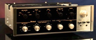
Rotel RB-1582 MkII Silver
Rotel RB-1582 MkII Silver Photo: Rotel
Users find many advantages in this model, for example, a very rich sound. The owner of the device will have full control over the sound. The device is reliable and will last a long time; you will not find complaints about poor quality assembly from owners online. Balanced inputs are also available - this type of connection is often used in both recording studios and concert venues because it allows the use of long cables with minimal signal loss.
Main characteristics
| Number of channels | 2 |
| Front channel power | 200 W (8 ohms, 20 Hz - 20 kHz, harmonic distortion 0.03%) |
| Reproducible frequency range | 15 - 100000 Hz (+/-1 dB) |
| Signal to noise ratio | 116 dB |
| Power consumption | 1500 W |
Advantages and disadvantages
Large power reserve. Balanced outputs allow you to run long cables
Not the most attractive design - the model is a regular black box
show more
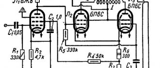
Power amplifiers
From the output of each filter channel, HF-MF-LF signals are fed to the inputs of power amplifiers, which can also be assembled using any of the known circuits, depending on the required power of the entire amplifier. I made the UMZCH according to the long-known scheme from the magazine “Radio”, No. 3, 1991, p. 51. Here I provide a link to the “original source”, since there are many opinions and disputes regarding this scheme regarding its “quality”. The fact is that at first glance this is a class “B” amplifier circuit with the inevitable presence of “step” distortion, but this is not so. The circuit uses current control of the transistors of the output stage, which allows you to get rid of these shortcomings during normal, standard switching on. At the same time, the circuit is very simple, is not critical to the parts used, and even the transistors do not require special preliminary selection of parameters. In addition, the circuit is convenient in that powerful output transistors can be placed on one heat sink in pairs without insulating spacers, since the collector terminals are connected at the point " output”, which greatly simplifies the installation of the amplifier:
Useful: Voltage converter on a 555 chip - circuit and details
When setting up, it is only IMPORTANT to select the correct operating modes of the transistors of the pre-final stage (by selecting resistors R7R8) - at the bases of these transistors in the “rest” mode and without load at the output (dynamics) there should be a voltage in the range of 0.4-0.6 volts. The supply voltage for such amplifiers (there should be 6 of them, accordingly) was raised to 32 volts with the replacement of the output transistors with 2SA1943 and 2SC5200, the resistance of resistors R10R12 should also be increased to 1.5 kOhm (to “make life easier” for the zener diodes in the circuit power supply of input op-amps). The op-amps were also replaced with BA4558, in which case the “zero setting” circuit (outputs 2 and 6 in the diagram) is no longer needed and, accordingly, the pinout changes when soldering the microcircuit. As a result, when tested, each amplifier using this circuit produced power up to 150 watts (short-term) with a completely adequate degree of heating of the radiator.
I would still recommend looking at the information in the “original source” for more information about this amplifier; the options, principles of construction, configuration and operation are described there in great detail.
Sound
The amplifier produces a very free, beautiful sound with excellent detail, rich timbres and long natural after-sounds of live instruments. The scene is built as accurately and as large as possible, with reliable representation of the proportions and location of virtual sound sources in space. Everything is quite consistent with the idea of how a good High End amplifier should play. There is no synthetics, harshness or “discreteness” that some adherents of the old school find in the sound of class D. On the contrary, the Marantz PM-KI RUBY successfully combines the best objective characteristics with the signature sophisticated and effortless presentation of musical material.
This typically “Marantz” sound manifests itself, first of all, in excessive intelligence when playing metal and hard rock. At the same time, classics of any composition, jazz and vocals sound very lively and natural. A very similar, perhaps even slightly more beautiful and sugary sound character was exhibited by Marantz amplifiers of previous years operating in class AB, which allows us to conclude that the sound of class D power amplifiers is neutral.
Connecting acoustics of different power, with different sensitivity and different impedance to the Marantz PM-KI RUBY amplifier gave the quite expected result: the absence of any pronounced reaction to changes in these parameters. The amplifier handled any stereo pair equally confidently.
Even under the most difficult load and at high volume, the lower notes of the double bass were surprisingly consistently reproduced - they sounded absolutely clearly, without hum, with a natural transmission of the sensation of a vibrating string and the soundboard of the instrument responding to this vibration. In a word, everything happened exactly as it should happen with an amplifier that has the declared combination of power and damping factor.
ULF power supply
Two transformers with blocks of rectifiers and filters were used as a power supply according to the usual, standard scheme. To power the low-frequency band channels (left and right channels) - a 250-watt transformer, a rectifier based on diode assemblies such as MBR2560 or similar, and 40,000 microfarad x 50 volt capacitors in each power arm. For the midrange and high-frequency channels - a 350-watt transformer (taken from a burnt-out Yamaha receiver), a rectifier - a TS6P06G diode assembly and a filter - two capacitors of 25,000 uF x 63 volts for each power arm. All electrolytic filter capacitors are shunted by film capacitors with a capacity of 1 microfarad x 63 volts.
In general, the power supply can have one transformer, of course, but with its corresponding power. The power of the amplifier as a whole in this case is determined solely by the capabilities of the power source. All preamplifiers (timbre block, filters) are also powered from one of these transformers (possibly from any of them), but through an additional bipolar stabilizer unit assembled on a KREN (or imported) MS or using any of the standard transistor circuits.
Comparison table of characteristics
| Model | Type | Signal to Noise Ratio | frequency range | Price |
| Pioneer A-50DA | Integral | 101 dB and above | 5 Hz - 50 kHz | from RUR 68,990 |
| Sony STR-DH790 | AV receiver | 105 dB | 10 Hz - 100 kHz | from RUR 42,990 |
| YAMAHA A-S501 | Integral | 99 dB | 10 Hz - 100 kHz | from RUR 49,990 |
| Denon AVR-S750H | AV receiver | 98 dB | 10 Hz - 100 kHz | from RUR 59,990 |
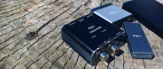
| Fiio BTR3K | Bluetooth receiver | 120 dB | 20 Hz - 40 kHz | from 5,660 rub. |
| Denon PMA-800NE | Integral | 105 dB | 5 Hz - 100 kHz | from RUR 54,990 |
| Beyerdynamic | For headphones | 110 dB | 20 - 20,000 Hz | from 7,990 rub. |
| Denon AVR-S960H | AV receiver | 100 dB | 10 Hz - 100 kHz | Price: from 74,990 rub. |
Homemade amplifier design
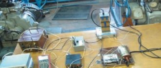
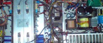
This was, perhaps, the most difficult moment in manufacturing, since there was no suitable ready-made housing and I had to come up with possible options :-)) In order not to sculpt a bunch of separate radiators, I decided to use a radiator housing from a car 4-channel amplifier, quite large in size, something like this:
All the “internals” were, naturally, removed and the layout turned out something like this (unfortunately, I didn’t take a corresponding photo):
– as you can see, six terminal UMZCH boards and a pre-amplifier-timbre block board were installed in this radiator cover. The filter block board no longer fit, so it was secured to a structure made from an aluminum corner that was then added (it can be seen in the pictures). Also, transformers, rectifiers and power supply filters were installed in this “frame”.
The view (from the front) with all the switches and controls turned out like this:
Rear view, with speaker output terminals and fuse box (since no electronic protection circuits were made due to lack of space in the design and in order not to complicate the circuit):
Subsequently, the frame from the corner is, of course, supposed to be covered with decorative panels to give the product a more “marketable” appearance, but this will be done by the “customer” himself, according to his personal taste. But in general, in terms of sound quality and power, the design turned out to be quite decent. Author of the material: Andrey Baryshev (especially for the site 2shemi.ru ).
CHAPTER 4. USER INFRASTRUCTURE.
The entire music collection, as well as movies, are stored on a small home server, in the form of an old Lenovo Thinkpad X61 with Debian Stretch installed.
A server with 3TB of disk space is used as file storage (with access from all devices via NFS), torrent downloader, UPNP server, Nextcloud and Timemachine for Macs.
Both Raspberry Pi and Android TV box are connected to a common home network via Ethernet, with file access via NFS (Kodi on the TV box).
For Raspberry Pi I used different distributions (Volumio, Runeaudio, Moodeaudio), and bare Raspbian with an MPD server installed, but finally settled on the Moodeaudio distribution (www.moodeaudio.org). This distribution seemed to me the most stable, actively developing, and with many working bonuses out of the box.
For remote playback on Raspberry Pi, you can use the following schemes:
— control playback of a music collection from the server via the Moodeaudio web interface:
— control playback of a music collection from the server via the Android application MPDriod
- using Raspberry Pi as a UPNP renderer from the J.River Media Center application (which I use as the main, most adequate application for Macos, for managing the music collection and synchronizing with storage devices for music in the car):
and through the Android application BubbleUPNP. I also sometimes use this application to remotely access my music collection on my home server.
I use MinimServer on Debian as a UPNP server.
I also really like the Cantata application, for accessing the MPD server on Moodeaudio, with downloadable covers and your own playlists. It is available for different platforms and is also being actively developed by the author:
Well, the simplest thing is to use the Raspberry Pi as an Airplay receiver and send a stream from Macos and iOS devices directly. We use this function periodically.
A very short video of using the device:
Project costs:
COMPONENTS:
| № | Name | Price, rub.) |
| 1 | Transformer (was available) | 3 000 |
| 2 | Textolite 200x300 | 500 |
| 3 | Parts for ULF TDA7293, power supply and input filter | 2 800 |
| 4 | Details for ULF Dorofeev | 600 |
| 5 | BP ULF Dorofeeva | 850 |
| 6 | Parts for AC protection device | 700 |
| 7 | Input selector on PGA2311 | 2 500 |
| 8 | I2C DAC (PiFi DAC) | 1100 |
| 9 | Raspberry Pi | 2500 |
| 10 | TVBox Tanix TX2 | 2600 |
| — | TOTAL COMPONENTS: | 17 150 |
CASE AND COMPONENTS:
| № | Name | Price, rub.) |
| 1 | Plywood 10 mm (sheet) | 850 |
| 2 | Oil | 350 |
| 3 | Potentiometer knob | 340 |
| 4 | Case fan | 170 |
| 5 | Connectors (BANANA) | 320 |
| 6 | HDMI extender | 120 |
| 7 | Case legs | 95 |
| 8 | RCA connectors | 115 |
| 9 | Power button | 210 |
| 10 | Subwoofer low pass filter | 130 |
| 11 | Front Panel Details | 200 |
| 12 | Fasteners | 300 |
| 13 | Wires, lugs, al.profiles (were in stock) | 500 |
| — | TOTAL CASE AND COMPONENTS: | 3600 |
TIME FOR MANUFACTURING AND ASSEMBLY
(days are still evenings, after work, sometimes weekends, but not full days)
| № | Name | Time (days) |
| 1 | Transformer rewinding | 2 |
| 2 | Manufacturing and assembly of ULF TDA7293 and PSU boards | 2 |
| 3 | Manufacturing and assembly of ULF Dorofeev boards | 2 |
| 4 | Manufacturing and assembly of power supply board (Dorofeev ULF) | 1 |
| 5 | Manufacturing and assembly of AC protection devices and input filter (2 pcs.) | 2 |
| 6 | Preliminary connection and testing of components | 3 |
| 7 | Making the case (3 days of which - oil coating) | 11 |
| 8 | Assembling components into the housing | 13 |
| — | TOTAL FOR MANUFACTURING AND ASSEMBLY: | 36 |
| add. | Preparation of the review | 3 |
More time was spent waiting for components and components; if you order cheaper, the delivery takes 2 months; sometimes a small thing slows down the whole process, although there was no need to rush.
PS We spent a long time celebrating the completion of work on the amplifier, but the cat went a little overboard:
We make an amplifier for a subwoofer with our own hands - 3 stages of assembly on the TDA1562Q integrated circuit
Any driver loves to listen to good music in his car. This entertainment lifts your spirits and helps you easily endure a long traffic jam. It is much more pleasant to perceive high-quality sound, and poor sound spoils the impression of listening to your favorite song.
Many motorists prefer louder music with good bass. A subwoofer can create the desired effect, but it requires an amplifier to function.
It is quite possible to make an amplifier for a subwoofer with your own hands, but before doing so, it is better to carefully read the recommendations.
To assemble a subwoofer amplifier with your own hands correctly, you need to stock up on free time and patience. You won't need to spend a lot of money. First of all, you need to purchase a power amplifier made on an integrated circuit. Next, we will look at how to assemble a subwoofer amplifier with your own hands based on the TDA1562Q chip.
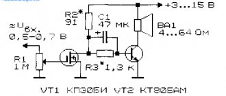
Amplifier circuit diagram
Below is a schematic diagram of the amplifier.
This circuit, in addition to the power amplifier, has a preamplifier made on a dual operational amplifier chip, which also plays the role of a frequency filter.
When powered by a car battery, the maximum output power of the amplifier will be about 50 W, which is quite enough to “drive” an average subwoofer.
Required equipment and components
So, in addition to the above microcircuit, we will need:
- operational amplifier TL 072 (can be replaced with TL 062, TL 082 or 4558 microcircuits);
- resistors with a power of 0.25-0.5 W;
- electrolytic capacitors (new!);
- non-polar capacitors - film;
- insulated wires;
- thermal paste;
- radiator with a dispersion area of at least 600 cm²;
- single-sided PCB sheet.
It is also recommended that the circuit be powered through a 10 A fuse and a choke, which can be “borrowed” from an old radio.
Of course, we can’t do without a soldering iron, solder and some skill in handling all this.
Installation
Main amplifier board
The amplifier circuit board diagram is shown below.
A printed circuit board can be made by etching a PCB with a copper substrate with a ferric chloride solution. It is easier to transfer the pattern of the contact tracks onto the board from a glossy sheet of paper on which this pattern is printed using a laser printer. The nuances of this method can easily be found on the Internet on relevant electrical engineering sites.
We solder the parts carefully, removing excess flux. This is especially true for microcircuits. The op-amp chip can be installed via the eight-pin panel.
The amplifier chip is installed on the heat sink. It must have an area of more than 600 cm². The role of a radiator can be performed by a car chassis.
After installing all the elements, connect the wires.
Power stabilization and communication unit
In the circuit described above, we used the simplest circuit for powering the amplifier through a battery, however, for more stable operation of the amplifier, you can connect it through a stabilizer. You can assemble this device yourself (a circuit for every taste can be found very easily on the Internet), but the easiest way is to use a ready-made stabilization unit from an old amplifier or buy a new one.
In addition, the stabilization unit allows you to save car battery power.
Discharge is prevented by a relay with a separate REM terminal, operating under a voltage of 12 V. The terminal is installed at the output of the car radio, thanks to which the subwoofer begins to work together with the music device.
To control the operation of the amplifier, you can install an LED in the power supply circuit of the device.
Final assembly of the device
After mounting the board, we complete the final assembly of the amplifier and place it in the housing. The body can be made independently from ordinary plywood using a jigsaw. A diagram of the required dimensions is drawn on plywood, cut out with a jigsaw and secured with sealant.
This is interesting: How to make the rear bumper of a UAZ Hunter yourself
- You can also purchase the case in a store or use an aluminum box, which will simultaneously act as a radiator.
- When placing all the parts in the case, you need to ensure free air circulation in it for better cooling of the parts.
- The amplifier housing must be securely fastened in the car.
- Before installation, it is important to make sure that the power polarity is correct, otherwise the device will immediately burn out.
Functionality check
We figured out how to make an amplifier for a subwoofer, all that remains is to check its performance. This can be done at home, but in no case should you neglect safety rules, otherwise you may get an electric shock or damage the device. Testing is carried out as follows: the amplifier is powered through a battery and a speaker with a resistance of 20 ohms is connected. A load is applied to the amplifier and the power is checked.
If you do not have basic knowledge of radio electronics, it is better to check the functionality by installing the amplifier in the speaker system. Before this, the radio is configured. If, after installing the amplifier into the system, you get the desired sound, then the amplifier is assembled correctly.
Conclusion
Installing an amplifier yourself has many advantages:
- High quality sound.
- High output power.
- Fairly simple assembly process.
- Saving money.
If you decide to build the amplifier yourself, take it seriously, read the exact description of the process and try to understand the essence. It is important to follow safety precautions while working.
The installation of each part must be done very carefully and carefully; there is no need to rush here, otherwise all the work will be in vain.
Check all contacts so that you don’t have to do this after installation in the audio system.
This description is suitable for beginners who have never encountered working with electronics. Making an amplifier with your own hands will allow you to significantly save on the purchase of this expensive device. Proper assembly can guarantee reliable operation and high-quality sound.