The presence of a certain number of acquaintances who are music lovers and musicians forces us to constantly repair, restore and refine various kinds of miracle technology, both from the “past, tube” times, and the present, digital ones. This business is not very profitable, and sometimes even unprofitable. but it is quite creative and always threatens with surprises and even new discoveries for oneself)) Since I am forced to deal with vinyl players simply ALWAYS, then, accordingly, I have already accumulated some experience in interfering with the insides of various Arcturus, Grundik, Duals, etc. And quite You can share some not-so-secret (!) moments with yourself))
Preamplifier-corrector circuits
There are a great many such circuits, but they are all the same in principle and circuit design and differ only in the ratings of the frequency-setting circuits and the element base used. Next, I will give a piece of text from the reference literature of “past” times:
“The quality of playback of a mechanical recording strongly depends on the parameters of the magnetic head of the pickup and the characteristics of the preamplifier-corrector. A corrector designed to work as part of high-quality equipment must have good technical characteristics: low self-noise and harmonic distortion, large dynamic range and amplitude-frequency response (AFC), the inverse frequency response of the recording channel during the “manufacturing” of a vinyl disc. The input and output impedances must also ensure normal matching of the magnetic head and the main 3H amplifier. At least previously, for most magnetic pickup heads produced by domestic and foreign industry, the average output signal level at a frequency of l000 Hz was unified with an amplitude of the needle oscillatory velocity of 10 cm/s within 2.5 mV. The optimal load resistance is 47 kOhm.
With this resistance for most heads, the absence of noticeable electrical resonances in the operating frequency range and the maximum signal-to-noise ratio are guaranteed. The distortion and noise introduced by the pickup head into the general sound reproduction path are small, therefore the degree of distortion and noise in the path is mainly determined by the characteristics of the corrector. Therefore, “standard” circuits are considered to be preamplifier-corrector circuits matched at the input to the output of magnetic pickups operating at a load with a resistance of 47 kOhm. For all correctors, the nominal input signal level is 2.5 mV, output resistance is 1 kOhm.”
The simplest corrector can be assembled with just two transistors, but this does not mean that it is “bad” - such an amplifier, with well-selected low-noise transistors with a high gain, provides quite decent sound. According to subjective assessments, the “transistor” sound is much more pleasant and “softer” than the microcircuit sound. Technical characteristics of this amplifier:
- Maximum input voltage…….. 40 mV
- Maximum output voltage…….. 4 V
- Overload capacity, not less than …….. 24 dB
- Gain at 1 kHz……. 100
- Deviation of frequency response from standard……… ± 1 dB
- Signal-to-noise ratio (not weighted)……. 65 dB
- Harmonic coefficient, no more than………0.1%
- Supply voltage………… 15 V
- Current consumption………….. 1.5 mA
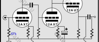
The circuit below is given as an example and taken from reference literature on amplifier circuitry:
However, corrector circuits on modern op-amp microcircuits also have high technical parameters and, at the same time, a smaller number of passive elements, do not require careful adjustment of individual stages, that is, they are easier to manufacture. In addition, transistor circuits tend to increase nonlinear distortion with a decrease in the frequency of the reproduced signal, and although this is eliminated by introducing deep feedback, it significantly reduces the level of the output signal and requires the use of additional intermediate amplification stages. Therefore, the preamplifiers-correctors I made were based on a standard classical op-amp circuit:
The microcircuit is connected according to a non-inverting amplifier circuit with a correction circuit R3C3R4C4 in the OOS circuit. The input resistance of the op-amp itself is high, and the resistance of the input stage is practically determined by resistor R1. Input capacitor C1 provides DC isolation and. In addition, together with resistor R1, it forms a low-pass filter that attenuates unwanted ultra-low frequency signals created by the mechanical moving parts of the electrophone. Resistor R2 determines the gain of the cascade and allows it to be adjusted if necessary. When using parts with the ratings indicated in the diagram, the equalizer gain at a frequency of 1000 Hz is 80 (38 dB).
The “native” original circuit was assembled at one time on the “ancient” op-amps K153UD2, K.140UD7, K140UD8, K140UD6, K153UD1, K153UDZ, now you can successfully use any modern microcircuits When connecting the corrector to a power source (bipolar, stabilized, voltage ±12…18 V) it, as a rule, begins to work normally provided that all elements are in good working order and there are no installation errors. No adjustment is required, but you can adjust the transmission coefficient of the amplifier by selecting the resistance of resistor R2. And by selecting capacitors C3, C4, you can regulate the rise or suppression of high and low components of the frequency response. The harmonic coefficient of the corrector at a frequency of 1 kHz does not exceed 0.03%.
A similar circuit was assembled in a version with unipolar power supply (+15...18 volts):
But still, the option with bipolar power supply is preferable for normal operation of the microcircuit.
For those who want to experiment, I propose another circuit from the reference literature - a corrector based on one op-amp with a low-noise transistor stage at the input. In this corrector, to reduce noise at the input, a differential stage is installed on low-noise transistors, which makes it possible to combine the simplicity of an on-chip corrector with the ability to obtain low noise through the use of such an input stage. The corrector has the following main technical characteristics:
- Maximum input voltage…….. 120 mV
- Maximum output voltage. . . … … 9.5 V
- Overload capacity, not less than …….. 33 dB
- Gain at 1 kHz……. 80
- Deviation of frequency response from standard……… ± 1 dB
- Signal-to-noise ratio (not weighted)……. 66 dB
- Harmonic coefficient, no more than . . . …..0.08%
- Supply voltage………… ±15 V
- Consumption current…………. . 10 mA
To obtain minimal noise in the input stage, the collector current of transistors VT1 and VT2 is also set to a minimum - about 50 μA. Capacitor C2 ensures the stability of the RF corrector. The corrector has no other features and can be assembled on a modern element base without any changes:
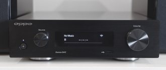
Naim Phono Preamplifier Kit
I bought an old vinyl player to integrate it into an even older radio. Naturally, a phono stage was also needed to amplify and correct the signal from the pickup head (MM). For the sake of one copy, drawing a board and waiting for production was naturally too lazy and pulled me to the vastness of Aliexpress for a kit for assembling it.
I must say that the experience of assembling power amplifiers from Chinese kits led me to some suspicions, and this time the choice was not based on price, or rather on price, but on the larger side. Again, thanks to the power amplifiers, the choice fell on a phono stage from NAIM.
I found a very interesting manufacturer and seller of a kit for assembling and bare circuit boards, noticeably more expensive than the others, but in appearance and according to reviews it was worth it. I ordered it before NG and finally received the parcel.
Unpacking and Inspection
The parcel arrived in a box and not in a bag, the box inside is lined with foam plastic, then the bag with the contents is wrapped in isolon, the packers, by the way, are also made of very thick polyethylene. Perhaps for the first time, a seller from China does not skimp on packaging.
The scarves are made using a method I don’t understand, it seems that the copper tracks are painted yellow or golden, the silk-screen printing is white and there is also a layer of varnish. The board is wired according to NAIM (apparently a copy) with a funny common ground. All holes on the filled ground are made with a thermal break; soldering will be problem-free.
Components
The first manufacturer in my memory who gives an installation specification in the product description, naturally the names and ratings of the components are written there. It looks like this on the screen:
Oddly enough, even the manufacturers of all the components on which you can see at least something coincided. Resistors are really 1%.
Capacitors:
Fasteners, for the first time in the set there are even bronze racks, and lower as I need them. The terminal block is only power supply, the input-output is soldered, which is justified in this case.
Resistors, each one was measured according to tradition, all really with an accuracy of 1%. One larger one for the power supply, probably 1W.
Semiconductors
Well, the board itself is simply perfect. As the assembly showed, all the holes are correct, neither more nor less.
Assembly
In order not to look for someone somewhere on the glare board, he printed out the manufacturer’s drawing and looked for it on paper. Again, this sheet will be useful during setup.
In addition, the following truncated diagram should help with setup:
Everything is standard here, first the resistors. I measured it so there were no surprises. It is difficult to set up a phono preamplifier with the wrong ratings; it is not only an amplifier, but also greatly breaks (corrects) the frequency response.
Next are smaller transistors, there are two types of them: BC550 and BC560. As usual, I soldered several at once, one leg at a time, starting with the collector.
Then the power supply and 100 mKf capacitors
Then there was a small snag because the green electrolytes did not have a minus symbol, there was a suspicion that they were non-polar - and that’s what happened. As a result, it was soldered as in the seller’s picture.
Conclusion
The set is almost perfect, there is nothing to complain about. But of course, this is not at all free, as always.
The seller has separate boards for any product, assembly kits and assembled boards. The price tag between the last two varies quite a lot.
Separately, the boards are also expensive, I figured that if I collected the loose stuff here, buying only the boards, it might turn out to be a little cheaper, although given the four non-polar electrolytes, that’s probably what it’s all about.
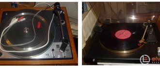
Main difficulties
Players from “reputable” and well-known companies, as a rule, do not contain any pre-amplifiers, at least I come across just such ones. They simply have direct output from the pickup. Some explain this by saying that all preliminary amplification stages should be located as far as possible from sources of strong interference and interference, such as, for example, electric motors and transformers. Good turntables often use small, low-voltage DC motors with a power supply in the form of a remote “adapter.”
This apparently makes sense. In any case, the preamplifier-corrector must be placed in a shielding metal case connected to the “Common” wire of the circuit (!) and it is also advisable to take the power supply for it outside (make it in the form of an “adapter”), or also carefully shield it.
Complex power supply
To power the amplifier and preamplifier, a symmetrical voltage of +/- 24 V is used, obtained from the stabilizers
and 7924 , amplified by transistors BD243C and BD244C, due to the maximum current consumption of the amplifier up to 3 A.
Useful: Scheme of a multi-channel remote control via cable or radio channel
The remaining components are supplied with a symmetrical voltage of +/- 5 V. Stabilizers 7805 and 7905 . The stabilizers are powered from a 100 W 230/2×24 V toroidal transformer.
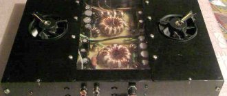
Examples of finished structures
All metal parts should be connected to the "Common" wire (GND) at one point, usually at the input of the preamp board.
Especially for the site Electrical Schemes - Andrey Vladimirovich Baryshev
- PREAMP FOR RECORD PLAYER
- VINYL PREAMPLIFIER RIAA
- PHONO EQUIPMENT DIAGRAM FOR VINYL
- SIMPLE PHONO PREAMPLIFIER
Launch and testing of the audio complex
After connecting, it turned out that everything worked perfectly, in the opinion of a (non)audiophile, there was no noticeable sound distortion, only a barely audible background from the 50 Hz network. It's really only barely audible when you put your ear close to the speakers, so you can put up with it.
The volume of the amplifier is sufficient for the room; while listening, you are unlikely to have to turn the volume by more than half. The connected speakers are 20 W (LF) and 5 W (HF) taken from an old tape recorder.
Expenses. The cost turned out to be quite reasonable. Transformer 500 rub. Integrated circuits ( TDA7265, TDA7050, TDA2320, KA2281, 4052 ) 500 rub. The rest of the electronics are the same, totaling one and a half thousand.
When repeating the circuit, you can change the configuration of the housing in order to eliminate or reduce crosstalk from the network; it is probably worth replacing the housing with a metal one and making a screen between the transformer and the audio circuits. You can use slightly larger filter capacitors, and also introduce a delay in connecting the speakers to eliminate clicks when turning the amplifier on and off.