All pin connectors (plugs) from this family have a metal jacket with a diameter of 13.2 mm with a protrusion (“key”) that specifies the orientation when connecting the plug to a socket. A number of connectors of a similar shape differ only in the configuration of the pins and are standardized in the documents DIN 41524 (three- and five-pin), DIN 45322 (6-pin at 60°), DIN 45326 (8-pin), DIN 45329 (7-pin) and other standards for various applications.
The plugs consist of a cylindrical metal skirt that protects several straight, round pins. The skirt is keyed to ensure that the plug can only be inserted into the socket in one position and to protect the contacts from damage. The basic design also ensures that the shield of the plug and socket is connected before all other contacts. However, because the key location is the same for all connectors, the key does not prevent incompatible connectors from being connected, which could cause damage. The situation has changed with Mini-DIN connectors, which have different keys on different types of connectors.
There are seven common layouts with a number of pins ranging from three to eight. There are three different five-pin connector types, with angles of 180°, 240° and 270° between the first and last pins (see illustrations above). There are also two options for seven-pin and eight-pin connectors: 360° and 270° [1]. There is some limited compatibility. For example, a three-prong plug will fit into any five-prong 180° socket and engage three prongs, leaving the other two unconnected. A 180° five-pin plug will fit into a seven- or eight-pin socket. Some high-end equipment used seven-pin connectors in which the two outer pins carried digital system data [2]: if the connected equipment was incompatible, the two outer pins could be removed from the plug so that they fit into standard five-pin 180° sockets without connecting data lines .
Screw-locking versions of these connectors have also been used in instrumentation, production control and professional audio applications [3] . In North America, this type is often called a “small Tuchel” connector, after one of the major manufacturers. Tuchel is now a division of Amphenol. The pin layout is almost the same as non-latching connectors, and in some cases, non-latching and non-latching connectors can be connected to each other. Additional configurations of up to 24 pins in the same shell are also available. In the 1980s, portable tape recorders and voice recorders sometimes used a bayonet-mounted version.
Speaker connectors [ edit | edit code ]
A polarized, two-pin, unshielded connector designed to connect a loudspeaker to an audio power amplifier (or other device; many of the early portable tape recorders used such connectors) is known as the DIN 41529 loudspeaker connector. It comes in panel-mounted receptacle and wire-mounted receptacle/plug versions. The plug has a flat center contact and an off-center round contact. The round contact must be connected to the positive pole (red), and the flat contact to the negative pole (black) [4].
In the Soviet Union and now in Russia, it is unofficially called the “dot-dash connector” [5].
This connector can now be found mainly on older equipment such as 16mm film projectors and the Becker radio found in many Mercedes-Benz vehicles. The same connector is used to connect some halogen lamps to a power source, as well as in Soviet Hi-Fi amplifiers and German vintage acoustics and amplifiers/receivers.
While all other versions of DIN plugs are quite reliable, this two-pin DIN plug is listed in second place - due to the lack of an external shield, it is much easier to accidentally pull out the plug. It’s easier to bend or move the contacts. Also, the plug does not sit so firmly in the socket - used copies are known for their unreliability. It is often enough to push them slightly, and the contact is broken.
Types of USB connectors, main differences and features
The Universal Serial Bus comes in 3 versions - USB 1.1, USB 2.0 and USB 3.0. The first two specifications are completely compatible with each other; bus 3.0 is partially compatible.
USB 1.1 is the first version of the device used for data transfer. The specification is used only for compatibility, since 2 operating modes for data transfer (Low-speed and Full-speed) have a low speed of information exchange. Low-speed mode with a data transfer rate of 10-1500 Kbps is used for joysticks, mice, and keyboards. Full-speed is used in audio and video devices.
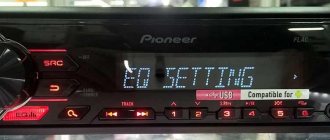
A third operating mode has been added to USB 2.0 - High-speed for connecting information storage devices and video devices of a higher organization. The connector is marked with HI-SPEED on the logo. The information exchange speed in this mode is 480 Mbit/s, which is equal to the copy speed of 48 MB/s.
In practice, due to the design and implementation features of the protocol, the throughput of the second version turned out to be less than declared and amounts to 30-35 MB/s. The 1.1 and 2nd generation Universal Bus specification cables and connectors are identical in configuration.
The third generation universal bus supports a speed of 5 Gbps, equal to a copy speed of 500 MB/s. It is available in blue, which makes it easier to determine whether the plugs and sockets belong to the advanced model. Bus 3.0 current increased from 500 mA to 900 mA. This feature allows you not to use separate power supplies for peripheral devices, but to use the 3.0 bus to power them.
Applications [ edit | edit code ]
Analog audio [edit | edit code ]
3/180° and 5/180° connectors were initially standardized and widely used in Germany, Czechoslovakia and, later, in the USSR and CMEA countries for connecting analog audio equipment, such as a stereo tape recorder with a stereo amplifier or preamplifier. Four contacts were used for the signal and a fifth for the common wire. The patch cords had a connector at each end, and the contacts were connected one-to-one: contact 1 with contact 1, 2 with contact 2, etc. The contacts on the plugs are numbered (from right to left, looking from the outside of the connector, contacts up ): 1-4-2-5-3. The holes in the sockets are also numbered 1-4-2-5-3, but from left to right (looking at the holes). This numbering is used because the base was a three-pin connector with a natural numbering of 1-2-3, and then pins 4 and 5 were added to it. Since a three-pin plug can be inserted into a five-pin socket, the numbers of the connecting pins are the same.
A four-channel wire wired in this way is sometimes simply called a DIN cord.
,
DIN wire
or
DIN cable
. For mono connections, 3/180° plugs are sufficient. When a mono plug is inserted into a stereo jack, it connects to the left channel, which is why some stereo equipment had mono/stereo switches. Such an interface was rare in the US market and gradually disappeared from new equipment, both in Germany and around the world, giving way to RCA (tulip) connectors. DIN connectors are still used in Naim Audio devices [6].
| Application | Connector | Assigning contacts | |||||
| 1 | 4 | 2 | 5 | 3 | |||
| amplifier | mono | 5/180° | sound output | screen/general | audio input | ||
| stereo | left channel output | right channel output | right channel input | left channel input | |||
| record player | mono | 5/180° | audio input | screen/general | sound output | ||
| stereo | left channel input | right channel input | right channel output | left channel output | |||
Other uses[edit | edit code ]
5/180° connectors were often used for:
- SYNC interface for electronic musical instruments;
- interface M >[7][8] );
- connecting two controllers of radio-controlled models for training purposes.
The DIN connector has seen other applications in its time besides audio. The TurboGrafx-16 game console used a 5-pin DIN connector for video and audio output. The Atari XEGS, along with the Commodore C64 and BK, used a DIN connector to connect to the power supply. Also, early C64s that only supported composite video output used a 5-pin DIN for video and audio, but newer C64s that supported chrominance/luminance output used an 8-pin DIN to carry additional signals. The Neo Geo and Neo Geo CD used an 8-pin DIN for composite video, RGB video, and mono audio outputs, as well as +5 V to power the RF modulator [9]. Dragon 32 computers used 4 5-pin DIN connectors for joysticks, tape recorder and monitor output. The TRS-80 Model I used three identical 5-pin DIN connectors for the power supply, video output and tape recorder, which made it easier to destroy the device if connected incorrectly. Much the same thing was observed in Soviet BC computers, which used four 5-pin DIN connectors for tape recorder, black and white video, RGB color video and power supply.
Soviet ONTs-VG connectors [edit | edit code ]
In the Soviet Union, 3- and 5-pin DIN connectors, called ONTs-VG, were used everywhere. The 5-pin connector was also called SSh-5, SG-5 (Ш - plug, G - socket), and the three-pin connector - SSh-3, SG-3. Initially, this was factory audio equipment, but then radio amateurs and cooperatives fell in love with this method of connecting equipment, and began installing such connectors in almost any device that dealt with low-frequency signals. It is impossible to talk about standard wiring of such connectors. While 3- and 5-pin connectors could be easily purchased, the situation with the rest was difficult. 4-pin connectors were not seen anywhere, neither on the equipment nor for sale. Six- and 7-pin connectors were difficult to obtain, and 8-pin connectors were very exotic.
As an example, we can mention the Soviet color TV “Raduga-315” with a 51 cm diagonal kinescope. It used a standard DIN-6 connector to connect a video signal source (for example, a VCR). Due to the fact that the signal playback mode on the TV was turned on with a separate button, a cable with an accessible SSH-5 connector was used to connect the VCR to the TV, the outer terminals of which 1 and 3 were simply bitten off with wire cutters, which ensured mechanical compatibility with the socket on the TV.
Since there were many non-standard ways to use connectors, only the standard ones are mentioned in the table.
| Contacts | Drawing | Fork | Socket | Standardized Application |
| 3 | ONTs-VG-2-Z/16-V | ONTs-VG-2-3/16-R | Monophonic connection of tape recorders to amplifiers, radios, microphones to tape recorders. Another name: SSH-3. | |
| 4 | Unknown | Unknown | Quite popular in the military industry. Other names: gx16 16m 4 | |
| 5 | ONTs-VG-4-5/16-V | ONTs-VG-4-5/16-R | Stereophonic and monophonic connection of tape recorders to amplifiers, radios, microphones to tape recorders, headphones to amplifiers. Other names: SSh-5, SG-5, DIN 41524, “5-pin DIN 180°”, DIN-5/180°. | |
| 5 | ONTs-VG-11-5/16-V | ONTs-VG-11-5/16-R | Headphones (plug) and equipment output for connecting them (socket) (not used since 1988) [10]. | |
| 5 | Unknown | ONTs-VG-11-6/16-V | ONTs-VG-11-6/16-R | Connecting VCRs to TVs. The direction of the signal is changeable, along each audio and video wire in two directions, depending on the “record/playback” mode. In the future, there will also be connection of household computers to TVs (black and white or composite signal). |
| 7 | ONTs-VG-11-7/16-V | ONTs-VG-11-7/16-R | Wired remote control for equipment. | |
| 8 | ONTs-VG-5-8/16-V | ONTs-VG-5-8/16-R | Connecting a car stereo to a car radio. Connecting a home computer and other RGB signal sources to a TV. |
Cable cutting.
You can prepare a cable in different ways, but the least traumatic method for conductors is to remove the insulation using a soldering iron.
Holding the soldering iron with one hand, rotate the shielded wire around its axis with the other hand, while pressing the insulation against the sharp edge of the soldering iron tip. https://oldoctober.com/
If after this you cannot remove the insulation by hand, you can use side cutters.
It should look something like this.
We also remove insulation from individual wires in the same way.
Now you can give the cable a look suitable for tinning.
Tinning.
Tinning is a mandatory procedure if the electrical elements were not prepared for soldering at the production stage.
In order to tin the conductors and plug contacts, you can apply them one by one to a piece of rosin and heat them with a soldering iron. In this case, there should be a drop of solder on the working surface of the soldering iron.
When using liquid rosin-based flux, you need to moisten the conductors and plug contacts one by one with the flux, and then heat it with a soldering iron with a drop of solder on the tip.
The use of active flux is allowed only for tinning, but not for final soldering.
When using active fluxes, rinsing of the solder is required.
The tinned end of the cable should look something like this.
Additional features - OTG
To connect peripherals and accessories to a smartphone via OTG, you need to use all 5 lines. The connection order does not change, with the exception of line 4, which is connected to line 5 - ground.
MicroUSB plug pinout for OTG operation.
Five-pin plug (ONTs-VG).
To disassemble the ONTs-VG plug, you need to press the tab with a screwdriver and remove the protective cap.
Don’t forget to put a protective cap on the cable and pieces of insulating tube (cambric) on the wires.
It is more convenient to solder the wires to the plug if you secure the latter with a clothespin, which, in turn, is pressed down to the table with something heavy.
Solder three wires one by one to the connector contacts.
It should look something like this.
The protective tubes can now be put on.
The arrow shows the cable fastening element, which does not allow securely fastening a thick cable.
If the cable is thick enough, and such cables are preferable when the connection length is several meters, then to securely fasten the cable you need to tightly wind 10-12 turns of thread in the place indicated in the picture.
Pinout of camera wires with backlight
The infrared illumination on the rear view camera displays the image in color in sufficient light, and in insufficient light, thanks to the IR illumination, displays the image in black and white at a distance of approximately 5 meters. So, their presence on rear-view cameras is relevant, unlike recorders, where they are of an advertising nature for “night photography” without practical application, which cannot be said about LED backlighting on rear-view cameras - it’s better without them than with them!
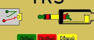
Installation of a 3.5mm Jack type plug.
On the market you can find inexpensive 3.5mm Jacks, whose pads intended for soldering are coated with nickel. Rosin and flux based on it are not suitable for soldering them. If you do not have active flux, you will have to use a sharp knife or scalpel to remove the coating from these areas and then tin them in the usual way.
When connecting a Jack plug to a thick shielded cable, you need to take into account that there is not much space under the Jack's protective cap.
The picture shows that the screen cores are twisted asymmetrically with respect to the cable wires.
As in the case of the previous connector, do not forget to first put the protective cap on the cable.
The wire formed by the twisted conductors of the screen should be shortened to avoid shorting it to the left channel.
We put protective tubes on the wires and solder them to the corresponding contacts of the Jack.
We slide the protective tubes onto the connector contacts.
Only now we solder the common wire to the connector.
Insert the cable into the fastening element. The arrow shows a fastening element whose dimensions are insufficient to securely fasten a thick cable.
As in the case described above, we will use sewing thread. To securely fasten the cable, you need to tightly wind 7-8 turns of thread No. 10.
Hold the cable and the ends of the thread with one hand, and with the other, using a soldering iron, apply a drop of melted rosin to the turns of the thread. Securing the ends of the thread with a knot can weaken the connection.
If you did everything correctly, then before final assembly, Jack should look something like this.
Now we bend the contacts of the left and right channels inward.
Pressing the Jack contacts, screw on the protective cap.
Connecting two car cameras to a monitor
The operating principle is such that when reverse gear is engaged, voltage is applied to the coil, the rear camera is turned on, and the power contacts of the front camera are open. When the rear camera is turned off, the relay is switched off and sent to the button through contact 87a plus. We turn on the button - the front camera works.
Soldering iron.
A soldering iron with a power of 25 - 40 watts is suitable for soldering connecting audio cables.
The pictures show the process of preparing two tips with diameters of 4 and 6 millimeters for operation.
In some cases, you may need to use a file to correct the shape of the soldering iron tip.
A properly sharpened soldering iron tip is convenient not only for soldering, but also for removing insulation.
The tip of a 40-watt soldering iron with a diameter of 6 mm, for ease of use, can be slightly narrowed with a file.
After the tip has acquired the required shape, it must be burned so that the oxide prevents the solder from spreading beyond the working area. For firing, just turn on the soldering iron for 20 - 30 minutes.
Now you need, with the soldering iron still turned on, to pass the file along the working surface of the tip several times to remove the oxide. Immediately after this, you need to immerse the tip in rosin, rub the solder ball with the tip and immerse it in rosin again.
Your soldering iron is ready to go.
USB Power Delivery Specification
| Profile | Possibility of delivery | Max power |
| 0 | Reserved | — |
| 1 | 5V and 2A | 2 W |
| 2 | 5V and 2A, 12V and 1.5A | 18 W |
| 3 | 5V and 2A, 12V and 3A | 36 W |
| 4 | 5V and 2A, 12V and 20V – 3A | 60 W |
| 5 | 5V and 2A, 12V and 20V – 5A | 100 W |
Neutral and active fluxes.
You can use any rosin as a flux, including: pine, violin, stage rosin, etc.
A solution of rosin in ethyl alcohol turns rosin into a liquid flux. Liquid flux not only allows you to get more beautiful soldering, but also removes heat from the elements in contact with the soldering area.
Rosin-based flux is neutral. It does not require subsequent flushing and cannot cause leaks in electrical circuits.
You can make liquid flux based on rosin yourself. To do this, you need to dissolve 2-3 grams of rosin in 20-30 grams of ethyl alcohol. It is better to use powdered rosin. A piece of rosin can be broken with a hammer, first wrapped in cloth.
Alcohol is extremely volatile, so liquid flux should be stored in a tightly closed container. You can use a bottle of nail polish, which also has a brush.
The use of so-called active fluxes is recommended only in extreme cases. Most often, this need arises when budget nickel-plated plugs are used. Moreover, this coating is also applied to the contacts intended for soldering.
After soldering using active flux, the soldering area should be thoroughly washed and then dried.
You can wash the soldering area with either an alcohol-gasoline mixture or ordinary water. If this is not done, then after some time problems may arise caused by oxidation of parts and leaks in electrical circuits.