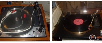
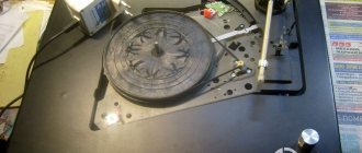
The presence of a certain number of acquaintances who are music lovers and musicians forces us to constantly repair, restore and refine various kinds of miracle technology, both from the “past, tube” times, and the present, digital ones. This business is not very profitable, and sometimes even unprofitable. but it is quite creative and always threatens with surprises and even new discoveries for oneself)) Since I am forced to deal with vinyl players simply ALWAYS, then, accordingly, I have already accumulated some experience in interfering with the insides of various Arcturus, Grundik, Duals, etc. And quite You can share some not-so-secret (!) moments with yourself))
Preamplifier-corrector circuits
There are a great many such circuits, but they are all the same in principle and circuit design and differ only in the ratings of the frequency-setting circuits and the element base used. Next, I will give a piece of text from the reference literature of “past” times:
“The quality of playback of a mechanical recording strongly depends on the parameters of the magnetic head of the pickup and the characteristics of the preamplifier-corrector. A corrector designed to work as part of high-quality equipment must have good technical characteristics: low self-noise and harmonic distortion, large dynamic range and amplitude-frequency response (AFC), the inverse frequency response of the recording channel during the “manufacturing” of a vinyl disc. The input and output impedances must also ensure normal matching of the magnetic head and the main 3H amplifier. At least previously, for most magnetic pickup heads produced by domestic and foreign industry, the average output signal level at a frequency of l000 Hz was unified with an amplitude of the needle oscillatory velocity of 10 cm/s within 2.5 mV. The optimal load resistance is 47 kOhm.
With this resistance for most heads, the absence of noticeable electrical resonances in the operating frequency range and the maximum signal-to-noise ratio are guaranteed. The distortion and noise introduced by the pickup head into the general sound reproduction path are small, therefore the degree of distortion and noise in the path is mainly determined by the characteristics of the corrector. Therefore, “standard” circuits are considered to be preamplifier-corrector circuits matched at the input to the output of magnetic pickups operating at a load with a resistance of 47 kOhm. For all correctors, the nominal input signal level is 2.5 mV, output resistance is 1 kOhm.”
The simplest corrector can be assembled with just two transistors, but this does not mean that it is “bad” - such an amplifier, with well-selected low-noise transistors with a high gain, provides quite decent sound. According to subjective assessments, the “transistor” sound is much more pleasant and “softer” than the microcircuit sound. Technical characteristics of this amplifier:
- Maximum input voltage. 40 mV
- Maximum output voltage. 4 V
- Overload capacity, not less than . 24 dB
- Gain at 1 kHz. 100
- Deviation of the frequency response from the standard. ± 1 dB
- Signal-to-noise ratio (not weighted). 65 dB
- Harmonic coefficient, no more. 0.1%
- Supply voltage. 15 V
- Consumption current. 1.5 mA
The circuit below is given as an example and taken from reference literature on amplifier circuitry:
However, corrector circuits on modern op-amp microcircuits also have high technical parameters and, at the same time, a smaller number of passive elements, do not require careful adjustment of individual stages, that is, they are easier to manufacture. In addition, transistor circuits tend to increase nonlinear distortion with a decrease in the frequency of the reproduced signal, and although this is eliminated by introducing deep feedback, it significantly reduces the level of the output signal and requires the use of additional intermediate amplification stages. Therefore, the preamplifiers-correctors I made were based on a standard classical op-amp circuit:
The microcircuit is connected according to a non-inverting amplifier circuit with a correction circuit R3C3R4C4 in the OOS circuit. The input resistance of the op-amp itself is high, and the resistance of the input stage is practically determined by resistor R1. Input capacitor C1 provides DC isolation and. In addition, together with resistor R1, it forms a low-pass filter that attenuates unwanted ultra-low frequency signals created by the mechanical moving parts of the electrophone. Resistor R2 determines the gain of the cascade and allows it to be adjusted if necessary. When using parts with the ratings indicated in the diagram, the equalizer gain at a frequency of 1000 Hz is 80 (38 dB).
The “native” original circuit was assembled at one time on the “ancient” op-amps K153UD2, K.140UD7, K140UD8, K140UD6, K153UD1, K153UDZ, now you can successfully use any modern microcircuits When connecting the corrector to a power source (bipolar, stabilized, voltage ±12.18 V) it, as a rule, begins to work normally provided that all elements are in good working order and there are no installation errors. No adjustment is required, but you can adjust the transmission coefficient of the amplifier by selecting the resistance of resistor R2. And by selecting capacitors C3, C4, you can regulate the rise or suppression of high and low components of the frequency response. The harmonic coefficient of the corrector at a frequency of 1 kHz does not exceed 0.03%.
A similar circuit was assembled in the version with unipolar power supply (+15.18 volts):
But still, the option with bipolar power supply is preferable for normal operation of the microcircuit.
For those who want to experiment, I propose another circuit from the reference literature - a corrector based on one op-amp with a low-noise transistor stage at the input. In this corrector, to reduce noise at the input, a differential stage is installed on low-noise transistors, which makes it possible to combine the simplicity of an on-chip corrector with the ability to obtain low noise through the use of such an input stage. The corrector has the following main technical characteristics:
- Maximum input voltage. 120 mV
- Maximum output voltage. . . . . 9.5 V
- Overload capacity, not less than . 33 dB
- Gain at 1 kHz. 80
- Deviation of the frequency response from the standard. ± 1 dB
- Signal-to-noise ratio (not weighted). 66 dB
- Harmonic coefficient, no more than . . . . 0.08%
- Supply voltage. ±15 V
- Consumption current. . 10 mA
To obtain minimal noise in the input stage, the collector current of transistors VT1 and VT2 is also set to a minimum - about 50 μA. Capacitor C2 ensures the stability of the RF corrector. The corrector has no other features and can be assembled on a modern element base without any changes:
Hi-Fi, Hi-End phono stage from any built-in Soviet
Using the example of 2 phono preamplifiers, I will show how ANY (correctly calculated) phono preamplifier can be easily raised to the level of the super cool, well-promoted KREK, NIKITIN and the like.
About 2 weeks ago they gave me an Arcturus 006. He restored the mechanics (it was never used or what? - the hitchhiking system worked immediately due to a manufacturing defect! The device was made in 1986). The GZM105MD head seems to be new. What about the phono stage? There is no good...
I restored it before - they are on the shelf Elektronika-012 (but need a new belt) and there is no built-in phono stage, and Radiotekhnika EP-101-stereo with a built-in phono stage, but the class is a bit low. Try to assemble circuits of 4 amplification stages, and the project was postponed for 2 years.
Analysis of the circuits showed 3 differences between the “cool” ones and the usual ones:
- the feedback capacitor must be non-polar if the amplifier power supply is 2-polar;
- there should be no capacitance in the feedback without a correction resistor (C11 and C12 in Arcturus-006 and C13+C14 with C15+C16 in BRIG 001);
- There must be a buffer stage (emitter follower) at the output of the amplifier because that the K157UD2 microcircuit in Arctur-006, and the KP303V in BRIG-001 have a large voltage gain and an insignificant current load;
- The output should have a non-polar capacitor of 0.67-1 µF. At large values, infra-low frequencies appear at the output, bending the woofer.
How to calculate a resistor?
For Brig-001, R27 = 113 kOhm, R28 = 16.2 kOhm = 16.2 kOhm → 113/16.2 = 6.975 kOhm.
Therefore, RHF correction → 16.2/6.975 = 2.32 kOhm.
Arcturus-006 is even simpler → 330 kOhm and 33 kOhm, respectively RHF correction = 3.3 kOhm:
The values should be taken to be smaller. So for Brig 2.2 kOhm, for Arcturus 2.7 kOhm with a difference in channels of less than 5%.
There will be no self-excitation - in BRIG C2, C5 are responsible for this; and Arcturus has C1, C2, C7 and C8.
At the beginning, it was planned to place the emitter follower after the output capacitor, but then a more elegant solution was found with fewer elements (it is precisely such solutions that are called engineering - reducing the number of parts while improving characteristics).
With Brig-001 there was generally good luck - the sound became at the level of the best rips of records made on equipment that cost 1000 bucks (the cost of only the player, head and phono stage). But Arcturus, although he began to play very well (in terms of transparency and low frequencies, is not inferior to Brig, but the background is too big. I redid the power supply, found that the KT814 rings correctly, but does not have a gain! I changed it, but the background remained - maybe the KT815 has it too equal to 10? I listened to Arcturus working through the Brig phono stage - the background is at the noise level! I assume the interference comes through a transformer from the pulse control of the engine. It’s hard to believe in the propagation of radio waves at 5.5 kHz (especially in their effective radiation). Or due to the lack of a capacitor at the entrance, or... But finding the background is a completely different story...
Theory confirmed by practice!
Author: Engineer
Main difficulties
Players from “reputable” and well-known companies, as a rule, do not contain any pre-amplifiers, at least I come across just such ones. They simply have direct output from the pickup. Some explain this by saying that all preliminary amplification stages should be located as far as possible from sources of strong interference and interference, such as, for example, electric motors and transformers. Good turntables often use small, low-voltage DC motors with a power supply in the form of a remote “adapter.”
This apparently makes sense. In any case, the preamplifier-corrector must be placed in a shielding metal case connected to the “Common” wire of the circuit (!) and it is also advisable to take the power supply for it outside (make it in the form of an “adapter”), or also carefully shield it.
MM corrector.
This part of the circuit is built quite standardly. of polystyrene capacitors is highly recommended here due to their low nonlinear distortion. The parallel connection of resistors and capacitors in this unit is intended to level out deviations of the values from the specified value in order to obtain maximum accuracy of the RIAA characteristics of the corrector. C22 - polystyrene.
Here, too, for a specific pickup, you need to select the values of elements C8 (from 0 to 330 pF) and R13 (minimum 220 kOm). An “electronic resistor” is assembled on the elements of IC4. Since the value of this resistor should be quite large - 47 kOhm, a regular resistor would significantly increase the noise level. The electronic version does not add thermal noise . The conversion of the R16 rating to a value of 47 kOhm occurs by applying a signal to its lower terminal in the circuit in antiphase to the upper terminal.
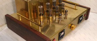
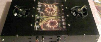
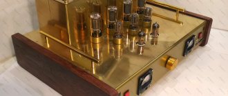
Examples of finished structures
All metal parts should be connected to the "Common" wire (GND) at one point, usually at the input of the preamp board.
Especially for the site Electrical Schemes - Andrey Vladimirovich Baryshev
The presence of a certain number of acquaintances who are music lovers and musicians forces us to constantly repair, restore and refine various kinds of miracle technology, both from the “past, tube” times, and the present, digital ones. This business is not very profitable, and sometimes even unprofitable. but it is quite creative and always threatens with surprises and even new discoveries for oneself)) Since I am forced to deal with vinyl players simply ALWAYS, then, accordingly, I have already accumulated some experience in interfering with the insides of various Arcturus, Grundik, Duals, etc. And quite You can share some not-so-secret (!) moments with yourself))
Design and setup.
The circuit is assembled on a double-sided printed circuit board.
The placement of parts is shown in the figure:
Click to enlarge
Assembled board:
Click to enlarge
The setup comes down to selecting elements R1, C1 and C8, R13 (C28, R49 and C35, R61) for specific types of pickups.
Preamplifier-corrector circuits
There are a great many such circuits, but they are all the same in principle and circuit design and differ only in the ratings of the frequency-setting circuits and the element base used. Next, I will give a piece of text from the reference literature of “past” times:
“The quality of playback of a mechanical recording strongly depends on the parameters of the magnetic head of the pickup and the characteristics of the preamplifier-corrector. A corrector designed to work as part of high-quality equipment must have good technical characteristics: low self-noise and harmonic distortion, large dynamic range and amplitude-frequency response (AFC), the inverse frequency response of the recording channel during the “manufacturing” of a vinyl disc. The input and output impedances must also ensure normal matching of the magnetic head and the main 3H amplifier. At least previously, for most magnetic pickup heads produced by domestic and foreign industry, the average output signal level at a frequency of l000 Hz was unified with an amplitude of the needle oscillatory velocity of 10 cm/s within 2.5 mV. The optimal load resistance is 47 kOhm.
With this resistance for most heads, the absence of noticeable electrical resonances in the operating frequency range and the maximum signal-to-noise ratio are guaranteed. The distortion and noise introduced by the pickup head into the general sound reproduction path are small, therefore the degree of distortion and noise in the path is mainly determined by the characteristics of the corrector. Therefore, “standard” circuits are considered to be preamplifier-corrector circuits matched at the input to the output of magnetic pickups operating at a load with a resistance of 47 kOhm. For all correctors, the nominal input signal level is 2.5 mV, output resistance is 1 kOhm.”
The simplest corrector can be assembled with just two transistors, but this does not mean that it is “bad” - such an amplifier, with well-selected low-noise transistors with a high gain, provides quite decent sound. According to subjective assessments, the “transistor” sound is much more pleasant and “softer” than the microcircuit sound. Technical characteristics of this amplifier:
- Maximum input voltage. 40 mV
- Maximum output voltage. 4 V
- Overload capacity, not less than . 24 dB
- Gain at 1 kHz. 100
- Deviation of the frequency response from the standard. ± 1 dB
- Signal-to-noise ratio (not weighted). 65 dB
- Harmonic coefficient, no more. 0.1%
- Supply voltage. 15 V
- Consumption current. 1.5 mA
The circuit below is given as an example and taken from reference literature on amplifier circuitry:
However, corrector circuits on modern op-amp microcircuits also have high technical parameters and, at the same time, a smaller number of passive elements, do not require careful adjustment of individual stages, that is, they are easier to manufacture. In addition, transistor circuits tend to increase nonlinear distortion with a decrease in the frequency of the reproduced signal, and although this is eliminated by introducing deep feedback, it significantly reduces the level of the output signal and requires the use of additional intermediate amplification stages. Therefore, the preamplifiers-correctors I made were based on a standard classical op-amp circuit:
The microcircuit is connected according to a non-inverting amplifier circuit with a correction circuit R3C3R4C4 in the OOS circuit. The input resistance of the op-amp itself is high, and the resistance of the input stage is practically determined by resistor R1. Input capacitor C1 provides DC isolation and. In addition, together with resistor R1, it forms a low-pass filter that attenuates unwanted ultra-low frequency signals created by the mechanical moving parts of the electrophone. Resistor R2 determines the gain of the cascade and allows it to be adjusted if necessary. When using parts with the ratings indicated in the diagram, the equalizer gain at a frequency of 1000 Hz is 80 (38 dB).
The “native” original circuit was assembled at one time on the “ancient” op-amps K153UD2, K.140UD7, K140UD8, K140UD6, K153UD1, K153UDZ, now you can successfully use any modern microcircuits When connecting the corrector to a power source (bipolar, stabilized, voltage ±12.18 V) it, as a rule, begins to work normally provided that all elements are in good working order and there are no installation errors. No adjustment is required, but you can adjust the transmission coefficient of the amplifier by selecting the resistance of resistor R2. And by selecting capacitors C3, C4, you can regulate the rise or suppression of high and low components of the frequency response. The harmonic coefficient of the corrector at a frequency of 1 kHz does not exceed 0.03%.
A similar circuit was assembled in the version with unipolar power supply (+15.18 volts):
But still, the option with bipolar power supply is preferable for normal operation of the microcircuit.
For those who want to experiment, I propose another circuit from the reference literature - a corrector based on one op-amp with a low-noise transistor stage at the input. In this corrector, to reduce noise at the input, a differential stage is installed on low-noise transistors, which makes it possible to combine the simplicity of an on-chip corrector with the ability to obtain low noise through the use of such an input stage. The corrector has the following main technical characteristics:
- Maximum input voltage. 120 mV
- Maximum output voltage. . . . . 9.5 V
- Overload capacity, not less than . 33 dB
- Gain at 1 kHz. 80
- Deviation of the frequency response from the standard. ± 1 dB
- Signal-to-noise ratio (not weighted). 66 dB
- Harmonic coefficient, no more than . . . . 0.08%
- Supply voltage. ±15 V
- Consumption current. . 10 mA
To obtain minimal noise in the input stage, the collector current of transistors VT1 and VT2 is also set to a minimum - about 50 μA. Capacitor C2 ensures the stability of the RF corrector. The corrector has no other features and can be assembled on a modern element base without any changes:
Choosing a phono stage - to each his own
Among vinylophiles, more and more new adepts of “live” mechanically extracted sound are regularly appearing. However, it should be noted that not everyone who gravitates toward devices resurrected from oblivion understands how to get truly high-quality and truly necessary sound. The RuNet is flooded with numerous reviews of turntables, where competent authors help neophytes of the vinyl craze purchase a suitable turntable. As a rule, amplification and acoustics already exist; there are also enough reviews devoted to them. But the choice of a phono stage already causes more difficulties for beginning hi-fi and hi-end lovers. As a rule, information about preamplifiers for vinyl is either articles about why a phono preamplifier is needed, or frankly advertising, uninformative posts describing specific models that definitely need to be purchased in “this” salon, et set era online store.
Built-in phono stage – good news for owners of “antique” amplifiers
The vast majority of older (25-30 year old) and some new amplifiers have a built-in phono stage. It is enough to connect the player to the input marked “Phono” and you already have a completely full-fledged sound picture. An important nuance is that in such systems it is necessary to take into account the compatibility of the corrector with the type of player head. Accordingly, the MM head will not sound adequately with the MS phono preamplifier.
Another option is a phono stage built into the player. In such cases, as a rule, the turntable will cost more. There will be no nuances with the type of head if the basic configuration is used (in any case, the technical documentation for such a player should contain appropriate notes). The advantage of such a preamplifier is maximum integration with the player’s circuit, although in budget turntables the above is not the rule (this is especially true for devices created in the Middle Kingdom). In addition to the advantages, the built-in phono correction has significant disadvantages.
The main disadvantage is low functionality.
It is known that the most accurate equalization can be achieved precisely at the preamplification stage. In the case of built-in options, the user of the device is limited by the capabilities of the amplifier. Another fact not in favor of the built-in phono correction (more often concerns cases of integration with an amplifier) is the inevitable increase in the nonlinear distortion coefficient. (more often applies to cases of integration with an amplifier) A general circuit with a large number of details will naturally have a negative impact on the sound. (The THD of the built-in preamplifier is often greater than that of an independent device). Of course, the above is not mandatory, but it is more likely, given the design features of such systems. Most discerning audiophiles prefer independent phono equalization.
Warm lamps are a pleasure, not for everyone
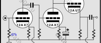
Many people recognize tube phono stages as one of the ideal preamplifier options for vinyl. Of course, the use of tube systems intentionally devoid of semiconductors creates a unique sound picture filled with even-numbered harmonics. The tube circuit will give the sound expressiveness and brightness. An equally wide and deep stage coupled with a clear warm sound, expressive lows and rich, slightly elevated mids does not leave many indifferent. But alas, this solution is not suitable for everyone. To fully experience the benefits and features of this type of preamplifier, you need an appropriate (tube!) amplifier.
Like any other technology, tube phono preamps have their drawbacks.
Compared to digital or hybrid systems, the equalization accuracy of an analog device will likely be lower. The functionality of lamp systems is also usually inferior. To reduce the level of distortion and achieve “pure analogue” sound, the design of tube phono stages is deliberately simplified. Probably the most serious disadvantage of tube preamp devices is their cost; sometimes they can cost an order of magnitude more than other types, especially for top models from well-known brands. Moreover, it is worth considering the service life of the lamps and the need for their periodic replacement after several years. The amount turns out to be very impressive. The cost of the device itself often significantly exceeds 60,000 rubles.
The myth of the cheap lamp
Today, there is a lot of budget lamp equipment - these are the so-called self-propelled or custom devices, among others, phono preamps. I would like to note that choosing a truly high-quality homemade device is difficult; this requires experience. Manufacturers, or sellers of such devices, can be subtle psychologists; as a result, an inexperienced novice audiophile can pay quite a large sum for a device that is not worth it, and it is not clear when it will fail. If you intend to purchase “homemade”, try to conduct a preliminary test, taking with you an experienced and competent person.
I won’t hide that there are truly reliable custom workshops and craftsmen who create unique and high-quality devices, but there are few of them and their products are not much cheaper, and in some cases more expensive, than factory ones. Almost everything that I have heard from artisans in one way or another does not reach the average figure, either the scene does not shine, or the averages are too low, or some strange background appears, or there is a crackling sound when you turn the resistor knob. Friends have had cases when (I emphasize, with proper operation and switching) an expensive amplifier and high-frequency speakers in no less expensive acoustics burned out. The artisan did not bear responsibility for his creation and said that the device was “misused,” which seems to hint at “high responsibility” and “firm warranty obligations.” Therefore, be careful.
Digital phono stages
One of the most common types of devices for pre-amplifying a vinyl player. We cannot talk about the uniqueness of the sound of digital phono stages, but their main advantage is the predictable result, at the expected level. Digital is more stable than analog delights. Expensive digital devices sound very decent. Many who can afford a lamp often choose the top series of digital and hybrid devices. This is especially typical for oldfags who gravitate toward clean, cold sound, happy owners of old transistor amplifiers with a dualmono circuit.
High functionality, often good clarity, sufficient low depth, excellent dynamics and a wide stage are the main advantages of digital phono stages.
There are very successful systems that can compete with a lamp in terms of stage depth and sound richness, but such devices rarely cost less than 15–20,000 rubles, and usually more. Main disadvantages:
• It’s not uncommon to get “sandy” when trying to seriously enhance the highs; • In budget models the sound is flat and trivial, there is not enough volume; • Almost everyone overestimates the average;
Hybrids – eat a digital one and play on a lamp
Some phono preamp manufacturers have followed the path taken by guitar equipment manufacturers before them. They attempted to combine tube amplification with the functionality and tuning precision of digital systems. Actually, get a warm tube sound with sniper-precise equalization and processing.
Phono stages created using a similar circuit can have both all the advantages and all the disadvantages of the systems described above. “True” adherents of tube sound consider the use of hybrids to kill the “correct” sound. I have heard several samples from the 60K+ price category and I can note that I did not find anything dead in this sound - they are very decent devices. The prices for these phono stages, as you probably guessed, range from simply high to exorbitant (over 100K).
Criterias of choice
For many, the criterion is price, which is not surprising - more about prices later in the text. The second important factor is the attitude towards music and the pretentiousness of the ears. If even minor distortions make you cringe, you’ve listened to classical music live all your life or are accustomed to studio conditions, get ready to shell out a hefty sum, and not just for a phono preamplifier. Let me remind you once again about the type of head - be sure to pay attention to what type of pickup head you have. Next, you will be faced with the question of choosing a circuit. If you have tube amplification and you feel a significant difference, a tube or a hybrid is your choice. If you need a relatively budget option and you won’t be sick of the “dead” sound, choose the number that suits you.
You may be satisfied with the built-in phono preamplifier; if you have not yet purchased an amplifier and player, pay attention to combined devices.
Regarding the choice of handicraft devices, it is difficult to advise anything significant, most of them are unpredictable and each is unique in its own way, but sometimes uniqueness is not for the better. Subjective assessment is the most important criterion. The perception of sound is a strictly individual process; we all hear differently. You need to go to the showroom or evaluate a similar device by listening to your friends. Ideally, the test listening will be carried out with the same player, main amplification and acoustics. For me, the ideal phono stage opens up a wide, spacious soundstage, has a rich, expressive sound, allows you to precisely set the equalizer settings (equipped with four equalization bands), gives a clearly distinguishable and dynamic sound, deep lows and balanced highs and mids. And also, I like the rather warm sound. You will understand what you like - the main thing is to listen.
Prices
Let's face it, in this type of technology, often the quality, detail, depth, stage and sound balance are directly proportional to the price. Accordingly, it makes sense to choose from devices in the price range from 7,000 rubles. Of course, there are several modest devices that have the right to exist for 3500 - 5000, but for a picky and demanding ear they will clearly not be enough. The sound of almost all budget phono stages is quite trivial; as a rule, there is not enough detail and depth of the sound stage. It should be noted that a cheap phono stage may well have a wide stage, deep lows and more than tolerable dynamics.
Main difficulties
Players from “reputable” and well-known companies, as a rule, do not contain any pre-amplifiers, at least I come across just such ones. They simply have direct output from the pickup. Some explain this by saying that all preliminary amplification stages should be located as far as possible from sources of strong interference and interference, such as, for example, electric motors and transformers. Good turntables often use small, low-voltage DC motors with a power supply in the form of a remote “adapter.”
This apparently makes sense. In any case, the preamplifier-corrector must be placed in a shielding metal case connected to the “Common” wire of the circuit (!) and it is also advisable to take the power supply for it outside (make it in the form of an “adapter”), or also carefully shield it.
