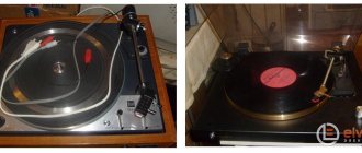
A vinyl corrector is an essential component of any vinyl disc player. The quality of playback directly depends on its quality. Today we will consider proven and repeatedly tested schemes according to which you can assemble a vinyl corrector.
I have already told you what RIAA correction is and why it is needed . Today we’ll look at a couple of op-amp-based vinyl corrector circuits. Both circuits were assembled and tested personally, and have been working perfectly for more than 5 years.
Vinyl corrector, circuit from datasheet on TDA2320A
The circuit is borrowed from the datasheet for the TDA2320A chip. It is essentially just a dual op-amp that can be replaced with any other dual op-amp without changing the circuit.
Operation with a unipolar supply voltage is ensured by supplying half the supply voltage to the non-inverting inputs (3 and 5) through the use of voltage dividers R1-R2-R5 and R3-R4-R6.
Capacitances C1, C2 and C14, C15 at the inputs and outputs of each channel are needed to cut off the DC voltage. It is advisable to place the 0.1 µF capacitor C13, which is necessary for filtering RF interference from the power supply, as close as possible to the pin of the microcircuit; in parallel with it, you can connect a capacitor with a capacity of 10-100 µF
↑ Housing
I made the sides from plywood and covered them with stain. I screwed the base to the sides using a wooden bead.
What is interesting about the TDA 2320A itself?
The feature of this microcircuit is that it is a class A amplifier. This means that both half-waves of the signal are amplified by one stage. In the case of class B, positive and negative half-waves are amplified by different cascades inside the chip.
A class A amplifier guarantees less nonlinear distortion. This microcircuit can operate both with a unipolar supply voltage from 3 to 36 volts and with a bipolar supply voltage from +-1.5 to +-18 volts, respectively. The pinout of the microcircuit is standard for operational amplifiers:
This chip is designed specifically for use in audio circuits, and the ability to operate at such a low supply voltage of 3 volts allows it to be used for portable devices, such as a cassette player. The datasheet provides examples of other filter and corrector circuits.
Main difficulties
Players from “reputable” and well-known companies, as a rule, do not contain any pre-amplifiers, at least I come across just such ones. They simply have direct output from the pickup. Some explain this by saying that all preliminary amplification stages should be located as far as possible from sources of strong interference and interference, such as, for example, electric motors and transformers. Good turntables often use small, low-voltage DC motors with a power supply in the form of a remote “adapter.”
This apparently makes sense. In any case, the preamplifier-corrector must be placed in a shielding metal case connected to the “Common” wire of the circuit (!) and it is also advisable to take the power supply for it outside (make it in the form of an “adapter”), or also carefully shield it.
Vinyl corrector with bipolar power supply
The following circuit was found in the book “The Art of Circuit Design” - P. Horowitz, W. Hill (p. 167). The diagram shows one channel of the vinyl corrector:
Essentially this is the same scheme. But now bipolar power supply is already used, and the ratings of the frequency-setting circuits are calculated differently. The use of bipolar power allows you to abandon both the use of dividers to form half the supply voltage and the output capacitor. The input capacitor should be left to cut off possible DC voltage from the previous stage, as well as an element of the input RC circuit.
In this circuit, as in the previous one, you should install power supply capacitances of 10-100 μF and 0.1 μF as close as possible to the power legs of the op-amp. A grounded 47 µF capacitor reduces the DC gain to unity.
The graph represents the frequency response of the playback amplifier plotted relative to a gain value of 0 dB at a frequency of 1 kHz.
TL062, TL072 can also be used as operational amplifiers, but it is better to give preference to TDA2320, L4558, LM833 and other op-amps intended for audio circuits, or those with high input impedance (>1MOhm), low noise level and high signal slew rate.
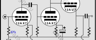
Tube phono stage
Phono stage assembly.
A phono preamplifier is an amplifier that restores the original spectrum of the audio signal recorded on a record, amplifying the output voltage of the pickup head to a typical line output level. I’m posting this mainly so that photos of the process don’t get lost and maybe someone will be interested in such a case.
Scheme:
Everything is distributed on two printed circuit boards. For opponents of printed circuit boards: you can grind the tracks, use a board with ready-made holes, with silk-screen printing, and with twist soldering. I ordered the transformer from Tortrans according to the specifications 220/130v 0.03A/22v 0.5A. Buying other radio components is not a problem.
Stainless steel case 3mm thick. The parts are laser cut.
Then I still had to turn to professional welders to eliminate the defects
After welding and cleaning the seams, there were several options for further processing: paint (but then you didn’t have to bother with stainless steel), matte or satin. I decided to try sandblasting.
The hole in the middle is threaded for attaching the transformer. Then it was welded and polished.
The outside was then polished to a mirror, it was not easy after sandblasting.
The front panel remains matte on one side.
I also experimented with glass for the front panel
I agree that the flower on top is a rather controversial decision. This is my first experience with stained glass, it didn’t work out the first time and required a lot of labor.
If you have questions about the scheme, you can find answers on the forum; there is a lot of useful information there that will help you avoid my mistakes. If necessary, I’ll post a printout later, after successful tests, but to be honest, I don’t think I’ll continue to work on it.
The files for cutting need to be adjusted a little, but now I understand that it can be done much simpler. There is most likely no practicality in the screen; the body should have been made a little longer so that there was 20cm between the lamps and the transformer. The flower can probably be removed. And we need to reconsider the mounting for the front panel; we had to drill holes for reliability.
For me this was the first and probably the last phono stage. First experience with stained glass, welding and polishing stainless steel. Perhaps, if I have some free time, I’ll work on a tube amplifier with this design, but that’s not certain). Overall I'm happy with the result, but I don't think it's worth the cost. insta And a few more photos.
↑ Assembly, PP
I won’t dwell on the description of the circuit - read in “Radio”, but I’ll tell you more about the implementation.
I did not install power on the board, I simply connected the wires to the existing stabilizers on the standard input selector board. I mounted the board itself on improvised stands above the selector pushers. Instead of KT3102/3107, modern transistors were used. After all, 30 years have passed (at the time of assembly), everything is developing and the element base is no exception.
Examples of finished structures
All metal parts should be connected to the "Common" wire (GND) at one point, usually at the input of the preamp board.
Especially for the site Electrical Schemes - Andrey Vladimirovich Baryshev
The presence of a certain number of acquaintances who are music lovers and musicians forces us to constantly repair, restore and refine various kinds of miracle technology, both from the “past, tube” times, and the present, digital ones. This business is not very profitable, and sometimes even unprofitable. but it is quite creative and always threatens with surprises and even new discoveries for oneself)) Since I am forced to deal with vinyl players simply ALWAYS, then, accordingly, I have already accumulated some experience in interfering with the insides of various Arcturus, Grundik, Duals, etc. And quite You can share some not-so-secret (!) moments with yourself))
All plugins and products - Plugin Alliance
All plugins and products - Plugin Alliance
NEW AND TODAY!
- $ 199
- ADPTR AUDIO
- Streamliner
- ★★★★★
- Featuring codec listening, automatic level matching and status measurement of volume and dynamics art.
- Mastering
- NEW!
- Secret Weapon
- $ 99 $ 49,99
- 149 99 dollars.99
- ★ ★★★ 349 $ 299,99
Monthly packages | Cash back up to $249.99 in vouchers!
- $ 10
- PA
- ESSENTIAL Bundle | monthly
- ★★★★★
- 40 plugins + 40 modular effects for only $10 per month! And a $99.99 voucher back after a year. A little EVERYTHING! Education prices for everyone. Includes 16 of our iconic brands!
- Prices for Education for All (EDU)
- NEW!
- 24 dollars.
99
- $ 19,99 $ 14,99
- $ 14.
99 $ 10
Annual packages | Cash back up to $249.99 in vouchers!
- $ 99,99
- PA
- ESSENTIAL Bundle | annually
- 40 plugins + 40 modular FX for only $99.99 per year! And receive your $99.99 voucher instantly by email. A little EVERYTHING! Education prices for everyone. Includes 16 of our iconic brands!
- Prices for Education for All (EDU)
- NEW!
- $ 199,99 $ 149,99
- $ 249
- Brainworx
- bx_oberhausen
- ★★★★★TM
Synt The World! Our bx_oberhausen synthesizer is a virtual instrument unlike any other.
Includes patented TMT&M/S features and offers a powerful suite of effects modules.
- Hardware emulations
- ★ ★ 199
- DS Audio Thorn
- ★
- Thorn is a virtual instrument that was designed to be easy to use and create truly modern sounds. And it will take you there in just a few clicks.
- $ 299
- $ 199
- $ 199
