Contents
- 1 Background
- 2 Phono stage circuit by John Broskie
- 3 Listening
- 4 New background corrector
- 5 Lamp selection
- 6 Transistor selection
- 7 Organization of bias of the first stage
- 8 Output transformers
- 9 Power supply
- 10 Delay of filament voltage and anode voltage
- 11 Corrector body
- 12 Parameters of my phono stage assembly
- 13 Results
- 14 Literature and sources mentioned
- 15 tracks digitized by my proofreader for listening
- 16 Projects of modules for EAGLE CAD
- 17 After what was written
↑ Background
The experience gained in the manufacture of my first phono stage was useful in the work. Tube preamplifier RIAA-phono stage.
First experience. The topic is the same - making a phono stage for your loved one. The birth of the brainchild was somehow difficult and took a very long time; the work on making a new corrector stretched out over time, flaring up and then dying out under the weight of everyday worries. Several times I stopped doing it altogether, pushing it into the far corner for a month, two, three and devoting myself to more important and urgent matters. Finally, the proofreader was completed and put into operation.
The reason for the manufacture of a new phono stage was the search for a circuit diagram of a Chinese clone of the Marantz 7 phono stage. Unlike the original, all stages of the clone were made on a 12AX7 lamp.
Rice.
1. Marantz 7 diagram
Rice. 2.
Scheme of the Chinese clone Marantz 7
RIAA correction is carried out in a frequency-dependent general feedback loop. Somewhere on the forum I came across that such circuits give a “rotten” sound. I cannot say categorically either. Personally, I didn’t like the following: strange male vocals, unnatural drums, no attack, no real punch, and the sound is inexpressive, it doesn’t take away. It seems to be playing, but somehow without a soul.
Rice. 3.
THD in percent
Fig.
4. Anti-RIAA
Rice. 5.
Dependence of THD on signal level
Rice. 6.
Clone's own noise
Rice. 7.
Noises by octaves
I don’t know what load this corrector is designed for. The capacity of the output coupling capacitor (in the device is 1 uF, although according to the circuit it is 2 uF) is not enough to work with an audio card with an input impedance of 20 kOm. The low-frequency rollover is equal to -3 dB already at a frequency of 60 Hz and -5 dB at a frequency of 20 Hz. Corrector lamps V1b and V2a operate in anode microcurrent mode. The coefficient of nonlinear distortion at low signal levels reaches 4%.
Vinyl corrector, circuit from datasheet on TDA2320A
Operation with a unipolar supply voltage is ensured by supplying half the supply voltage to the non-inverting inputs (3 and 5) through the use of voltage dividers R1-R2-R5 and R3-R4-R6.
Capacitances C1, C2 and C14, C15 at the inputs and outputs of each channel are needed to cut off the DC voltage. It is advisable to place the 0.1 µF capacitor C13, which is necessary for filtering RF interference from the power supply, as close as possible to the pin of the microcircuit; in parallel with it, you can connect a capacitor with a capacity of 10-100 µF
↑ Phono stage diagram from John Broskie
Why am I telling all this?
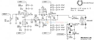
During my search, I noticed a phono circuit diagram on the TubeCad Journal website. Rice. 8.
Phono stage circuit
The scheme seemed interesting, I got excited and decided to repeat it. As they say, hunting is worse than bondage. I modeled the phono stage in an electronic simulator by replacing the 6JD8 tube with a 6N23P, the circuit is working, the parameters promise to be good. I wrote a letter to the author (John Broskie) to clarify the values of capacitors C1 and C2. I received a response with an attachment of a modified circuit and capacitor values for this modified circuit with another lamp in a cathode-coupled cascade. By introducing capacitor C1, the author proposes to reduce the background from anode voltage pulsation using a compensation method.
V. B. Grigorov “Reducing the noise level in low-frequency amplifiers” Mass Radio Library, 1956
“...An effective method of combating background is the use of various compensation schemes. The essence of this method is that a voltage at the background frequency is applied to the grid or cathode of any pre-amplifier tube (usually the first tube), and the phase and amplitude of this voltage are selected so as to ensure complete elimination of the background at the amplifier output. It should be noted, however, that the amplifier in this case must have a “normal” background level, that is, it must have a normally operating filter, since otherwise the application of too large compensating voltages to the grid or cathode of the amplifier tube may cause the operating point of the tube to transition to nonlinear section of the characteristic, which will increase nonlinear distortions..."
Rice. 9.
Compensation for 100 Hz ripple and harmonics
For this circuit, the values were selected in an electronic simulator.
For a 6N23P lamp Ku = 34, C1 from 10.7 to 11.7 nF. For a 6N23P-EV lamp Ku = 32.5, C1 from 11.6 to 12.6 nF, C2 = 1 uF. I think that this implementation of compensation for anode voltage pulsations is not very correct. It can be seen that the compensation efficiency depends on the gain of the lamp (for a 6N23P lamp a spread of +/-9 is allowed) and capacitance C1. It is necessary to select the capacitor value; there is no possibility of adjustment during operation when the lamp parameters change (aging, replacement). When using an anode supply stabilizer, this capacitor is not needed. The author recommends installing a diode between the anode of the first and cathode of the second lamp if a power source without a delay in the supply of anode voltage is used.
This time I decided to make the control units in separate modules and on printed circuit boards. The boards were laid out in the Eagle program, the free version of Light, which imposes restrictions on the size of the boards and the number of components on the board. I assembled a layout of one channel and started listening.
Rice. 10.
Photo of the module
Fig.
11. Anti-RIAA layout
Rice. 12.
THD layout
I would like to draw your attention to the fact that the M-Audio 2496 audio card cannot drive a low-impedance load, and the input impedance of the anti-RIAA circuit drops at high frequencies. The integrated audio card can operate at a resistance of 32 Ohms, but has parameters that are insufficient to use it as a measuring tool.
Below are images of the frequency response of the same module and the anti-RIAA chain, tested with different audio cards.
Rice. 13.
M-Audio 24/96
Rice.
14. Integrated audio card
↑ A little about details and training of capacitors
I would like to draw your attention to the fact that used parts must be carefully checked before being installed in the circuit.
Everyone has a tester; with its help you can select the necessary resistors with sufficient accuracy. If the measurement accuracy needs to be improved, then two testers, a stabilized power supply and Ohm's law can be used. It is advisable to train capacitors that have not been used for a long time, especially high-voltage ones. For training, you need a transformer with several windings, by switching which you can change the output voltage, a high-voltage diode and a resistor connected in series with the diode. You need to start training with 1/4 - 1/3 of the rated voltage, increasing it every other day. It is enough to keep the capacitor under voltage for 3 - 4 days. After training, the parameters of the capacitors improve.
You need to have a supply of lamps; you can select them based on the identity of the halves and noise after assembling the circuit.
The use of chokes or transistor filters in the power supply is at your discretion. I had chokes available, and I like the sound with chokes in the anti-aliasing filter more than with transistor anti-aliasing filters.
I do not discuss the types and brands of parts used; you will find a lot of material on this issue. I consider it appropriate to use what is available in my first design. Having gained invaluable experience, you will subsequently be able to assemble a super phono preamplifier from the most worthy parts.
↑ Listening
The perception of mono sound is very different from stereo, you need to get used to it.
I expected more from the circuit, I thought, I’ll turn it on and here it is, nirvana. But it didn't happen. I changed records, changed the phono stage, and connected mine in mono mode to compare the sound. First impressions are contradictory. The new circuit has a high resolution, as my friend said, “lays out the instruments on the shelves,” but the sound did not seem “comfortable.” I digitized several tracks using my phono stage in mono mode and a prototype of a new circuit, recorded the tracks on a CD and asked two of my fellow music lovers to listen and give their opinion. The tracks on the disc were arranged in random order; those listening did not know through which phono stage the recording was made.
As a result of blind listening, the first listener was unable to give preference to any of the devices. The second divided by genre, giving preference in rock music to the first (let’s call it old) corrector, noting that it “blurs” the sound, and in classical and instrumental music - to the second (new) phono preamplifier.
I, knowing where what was playing, also could not finally decide, although the second phono preamplifier was more “accurate”, but the “hard” and somewhat “tiring” sound did not give me rest.
I would like to note that all my home-grown definitions of sound, such as “precise”, “blurred”, “uncomfortable”, “hard”, “tiring”, etc., are very arbitrary and hardly perceptible when listening. Perhaps they are a consequence of self-hypnosis and do not deserve the attention of a serious reader.
↑ Impressions about the sound
Well, everything is assembled, correctly connected and turned on.
What happened? The phono stage's own noises begin to be heard when the ULF volume control is at 3 o'clock. No microphone effect was noticed. Tapping on the phono preamplifier body is not transmitted to the amplifier; in order to hear anything, you need to tap on the lamp cylinder. The output signal level is comparable to a CD player. The sound is good for my taste. You can hear the difference in the recording quality on the records, the sound is not tiring, you can listen for a long time. But we’ve already gotten out of the habit of cleaning off dust and turning over disks. Playing sound from a tape recorder through the line outputs is also not bad. If the recording quality is good, it plays great. Despite the more modest technical parameters than those of digital sources, vinyl players and tape recorders reproduce sound very well and it’s too early to bury them. There is something about analog audio sources that just doesn't let go. Maybe it's nostalgia for youth? Don't know. But this is all lyrics. Below are the technical parameters of my device that were measured.
↑ New background corrector
Nevertheless, searching, thinking, reading material, and so on began.
Since the circuit had attractive aspects - direct connection of the cascades, the absence of electrolytic capacitors in the cathode circuit, the capacitors of the correction circuit are under polarizing voltage, accessible parts, I still decided to find an acceptable solution for myself. I simulated the options in an electronic simulator; I really wanted to preserve the direct connection of the cascades. As a result, I settled on the following circuit: the first stage is a beta follower on a pnp transistor with LED bias, the second stage with cathode coupling remains unchanged.
Rice. 15.
Phono stage circuit.
↑ Lamp selection
In their article “RIAA amplifiers - corrections on vacuum triodes for “high-speed” (electrodynamic) pickups” E. Babichenko and I. Gaponov do not recommend using the 6N23P lamp in phono stages.
“...The two-stage 6N23P crunches disgustingly...” Apparently this means the use of this lamp in resistive cascades with a common cathode. Many negative reviews about the use of this lamp can be found on the Internet. In general, reviews about the sound of the 6N23P are very contradictory.
“LIFE IN A VACUUM” Bulletin of the Association of Russian Audiophiles. “...6922/6N23P-EV is perhaps the most “debated” lamp among signal lamps. As soon as someone criticizes her, someone else will immediately come to her defense. Glass Audio has two major articles with opinions on the suitability of the 6922 in audio circuits - “Suitability of the 6DJ8 for Audio”; GA 1995/3, R. Modjesky and “Is the 6DJ8 suitable for audio?” D. Danner. GA 2/93.
If readers are interested in this technical and musical debate, we will translate and publish it. Below is data obtained by Rickard Berglund (Sweden), published in GA 1995/6. Distortion values are given for an output voltage of 1 V (RMS).... Data were obtained on several circuits, for the “honesty” of the results, including a conventional amplification circuit (with a common cathode) with and without a shunted cathode resistor, a mu - follower (with a current generator in anode), SRPP with and without cathode resistor shunt, cathode follower and load-sharing inverter..."
Rice. 16.
From the data provided by Rick Berglund, it can be seen that the 6922 lamp manufactured by Sovtek has higher gain and lower distortion relative to its more famous analogues. I can’t say whether the 6N23P-EV lamp is a complete analogue of the 6922 Sovtek lamp.
I decided to use what was available. In the first stage, you could try 6N24P, which has a different pinout, is available and they ask for it several times less, but I still wired the board for a 6N23P lamp. Let it be possible, on occasion, to test lamps from different manufacturers (6922, 6DJ8, ECC88, E88CC, etc.) without remaking the board.
In the bins there were 23 6N23P lamps and 6 6N23P-EV lamps, new and used. A preliminary selection of lamps was carried out for the identity of the halves, based on noise and compliance with passport characteristics, and candidates for the project were selected.
In addition, I would like to quote E. Karpov: “The high linearity of the cascade with a current source and the improvement in the spectrum of the output signal significantly expands the range of tubes suitable for use in high-quality low-frequency amplifiers. Such traditionally maligned tubes as 6N2P, 6N3P, 6N23P show excellent results in linearity and sound quality.”
Rice. 17.
Single channel module
Resistor R11 is made up of two two-watt resistors of 10 kOm +/- 10%. A pair of resistors 9.1 and 12 kOm looks more promising. Resistors are placed above the board on stands due to decent heat dissipation. After raising the resistors above the board level, the temperature on capacitor C5 dropped to 52, and on C6 to 49 degrees. The temperature on the C 10 capacitor does not exceed 50 degrees, despite the proximity of the lamp. The temperature at the condenser C1 is 32, at C2 - 35, at C4 - 35 and at C8 - 30 degrees. It makes sense to replace two-watt resistors (R11, R12, R13, R14) with three-watt ones to reduce heat generation. The temperature on three-watt resistors in operating mode does not exceed 60 degrees, and on two-watt resistors it reaches 90 - 95 degrees. The temperature at the lamp cylinders is about 78 degrees, all measurements were carried out on an open structure. In a closed case the temperature will naturally be higher.
What is interesting about the TDA 2320A itself?
A class A amplifier guarantees less nonlinear distortion. This microcircuit can operate both with a unipolar supply voltage from 3 to 36 volts and with a bipolar supply voltage from +-1.5 to +-18 volts, respectively. The pinout of the microcircuit is standard for operational amplifiers:
This chip is designed specifically for use in audio circuits, and the ability to operate at such a low supply voltage of 3 volts allows it to be used for portable devices, such as a cassette player. The datasheet provides examples of other filter and corrector circuits.
↑ Transistor selection
Lecture No. 13. “Current sources on bipolar and field-effect transistors. Stabilizers."
“...In the circuit of a current source on a bipolar transistor, the latter must operate in the active mode, and its operating point will lie on a flat section of the current-voltage characteristic; the constructed load characteristic at the intersection with the static current-voltage characteristic should ensure the position of the RT on a flat section (DE)..."
Rice. 18.
It is clear that two volts is not enough for the transistor to operate at least in the initial section of the linear part of its current-voltage characteristic. Most likely, you need low-power transistors designed to amplify weak signals, with a low collector-to-emitter voltage drop and high gain. First I turned my attention to germanium transistors of the P401-402 series. But only transistors from older releases were available, which, according to their data sheet, have a maximum emitter current of 10 mA, and the measured gain turned out to be no more than 110. As a result of searches, tests and measurements, I settled on the next pair of candidates. These are a high-frequency low-power germanium transistor P416B and a silicon transistor for amplifying small signals STS1980. For the P416B, a spread of β is provided from 90 to 250, for the STS1980N from 120 to 240. It is advisable to select transistors with the maximum gain, because we count every “parrot”.
Morgan Jones “Tube Amplifiers” DMK Moscow 2007, p. 240
“...The equivalent resistance of the lamp on the anode side is defined as the product of Rk by β, that is, the lamp, as it were, multiplies Rk by β.
Likewise, a bipolar transistor multiplies any resistance in the emitter circuit by β or h21. Thus, the output characteristics of the transistor can be equalized by adding a resistor to the emitter circuit. Since h21 of a low-power transistor is approximately ~400, a 100 Ohm resistor in the emitter circuit gives an output resistance of ~40 kOm. The cathode follower multiplies this resistance by its β, for example 20. As a result, we obtain Rн ~8 MOm (the author was “ slightly
” mistaken, 40,000 × 20 = 800,000 kOm), which is even better than what can be achieved in a conventional β-follower. A β-follower can easily provide an equivalent output impedance of Rн>50Ra, even with a low β of the upper lamp..."
Operating mode of transistor P416B:
R5 = 75 Om, R6 = 18 kOm, Uce ~ 1.25 V, I = 10 mA.
Rice. 19.
P416B
The module parameters and sound are decent, the transistor can be used. There is one drawback, this is a large spread in the parameters of the transistors. You need a pair with similar parameters with a maximum gain; perhaps, several dozen transistors will be needed for selection. Of the 16 P416B pieces available, one had β=195, the closest ones had β=150 and 145, the rest had β from 88 to 115. The measurements were carried out with transistors that had β=195 and β=150.
Rice. 20.
THD with transistor P416B with β=195 in percent
Rice.
21. THD with transistor P416B with β=195 depending on the signal frequency
Rice. 22.
THD with transistor P416B with β=195 depending on the signal level
Rice. 23.
Internal noise of the module with transistor P416B with β=195
When trying to use a transistor with β=150, the total harmonic distortion increased uncritically from 0.012% to 0.015%, but the harmonic spectrum changed and the module’s own noise increased slightly (by 3 dB). The parameters also changed for the worse at low signal levels; at -40 dB, THD more than doubled. The increase in the second harmonic was insignificant, but the higher harmonics grew faster, which is not very good.
Rice. 24.
THD with transistor P416B with β=150 in percent
Rice.
25. THD with transistor P416B with β=150 depending on the signal level
Rice. 26.
Internal noise of the module with transistor P416B with β=150
Operating mode of the STS1980 transistor:
R5 = 75 Om, R6 = 9.1 kOm, Uce ~ 1.25 V, I = 10 mA.
Rice. 27.
STS1980
Of the four pieces, two transistors turned out to be with β=225. The parameters of the cascade are practically no different from the cascade with a germanium transistor P416B with β = 195. During the measurements, the same module and power supply were used, only the transistor current source was replaced. The values of multiple measurements turned out to be very close, both in terms of distortion and noise. It is clear that during the measurements there was a certain scatter of parameters; average values are given.
Next, I recorded several tracks using different transistors in the current source and recorded an audio CD with pairs of identical tracks. When listening, I did not hear any differences; everything played smoothly, naturally and pleasantly. A big plus is the presence of a pair of transistors with similar parameters and high β. In general, I settled on STS1980.
Rice. 28.
THD with transistor STS1980 in percent
Fig.
29. THD with transistor STS1980 depending on signal frequency
Rice. thirty.
THD with STS1980 transistor depending on signal level
Rice. 31.
Internal noise of the module with transistor STS1980
↑ Organization of bias of the first stage
I looked at LED bias and automatic bias with a large capacitor bridging the resistor.
Automatic offset allows the use of lamps with a greater spread of halves, although it does not exclude the selection of lamps. Unfortunately, the measurement results of the module with automatic bias and LED bias were not saved. There are only two screenshots left, with automatic bias in the first stage and an output level of 250 mV 1 kHz (-12 dB) and with LED bias in the first stage and an output level of 315 mV 1 kHz (-10 dB). In both cases, the level of the second harmonic is 70 dB lower than the first (~0.03%), the remaining harmonics are lost in noise. Automatic bias, 250 mV input signal. Rice. 32.
LED bias, 315 mV input signal
Repeated THD measurements were carried out on the assembled device with an output transformer stage and noise levels were measured. When performing THD measurements of an auto-biased and LED-biased phono stage, the parameters are very close (same channel with R3 and C2 replaced by an LED).
Rice. 33.
Auto offset
Rice.
34. Same module, LED bias
There is a difference in the level of intrinsic noise and interference when using different types of bias in the first stage of a given phono stage. When measuring parameters with different types of bias, it turned out that with LED bias the noise level is 3 dB lower and has a slightly different spectrum. I think that this depends on the different sensitivity of the LED and the resistor to electromagnetic interference from the transformer.
When biased by the LED, the stage noise has its greatest amplitude in the range from 20 to 40 Hz, then begins to gradually decrease. With a real amp and speakers (at maximum volume), it's like a steady blowing sound, soft and not annoying.
With automatic shifting, the noise spectrum is dominated by the frequency of 50 Hertz and its harmonics, 100, 150, 200 Hertz, etc. The nature of noise and interference with automatic shifting is perceived as louder and more unpleasant.
Rice. 35.
Left channel with auto shift, right channel with LED shift
Rice.
36. Both channels with LED bias
This is not critical, since no one will listen at full volume. On the other hand, selecting lamps for the first stage with automatic bias will be less problematic. If you place the phono preamplifier and power supply in different housings and separate them at some distance, then using automatic bias seems more preferable.
When listening to musical material, differences are at the level of “impression” and “appearance”. I think that during blind listening it will be extremely difficult or simply impossible to distinguish.
As a result, the module board is wired for automatic bias, but in the final version I used bias with an LED installed in the seat of the electrolytic capacitor C2. I continued to listen to the layout for some time, changing the musical material and making sure (convincing myself?) that this was the final version.
If the input sensitivity of your ULF is up to 500 mV, then an additional stage may not be needed; you will only need to reconsider the value of the output coupling capacitor C11. In my case, the capacitance of 0.47 uF is designed for the input resistance of the third stage of 166 kOm.
Module parameters:
gain at a frequency of 1 kHz ~68 (depending on the gain of the tubes used, in my case the spread was from 60 to 68). With an input signal of 2.5 mV, the output will be ~170 mV. THD 0.012%, unweighted noise 72 dB, measured under such “field” conditions.
Rice. 37.
Measuring the parameters of the phono stage module.
The power transformer is simplified; a second high-voltage anode supply stabilizer is not needed. But the nominal sensitivity of my ULF is 1 V and 170 mV at the input is not enough, you need to make a third stage. I haven't come up with anything better than a transformer stage with a gain of 3. The gain headroom is good, because when I got an MC head with a high output of 1.6 mV, I was able to listen to music without changing anything.
Hi-Fi, Hi-End phono stage from any built-in Soviet
Using the example of 2 phono preamplifiers, I will show how ANY (correctly calculated) phono preamplifier can be easily raised to the level of the super cool, well-promoted KREK, NIKITIN and the like.
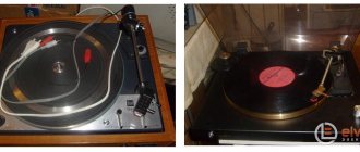
About 2 weeks ago they gave me an Arcturus 006. He restored the mechanics (it was never used or what? - the hitchhiking system worked immediately due to a manufacturing defect! The device was made in 1986). The GZM105MD head seems to be new. What about the phono stage? There is no good...
I restored it before - they are on the shelf Elektronika-012 (but need a new belt) and there is no built-in phono stage, and Radiotekhnika EP-101-stereo with a built-in phono stage, but the class is a bit low. Try to assemble circuits of 4 amplification stages, and the project was postponed for 2 years.
Analysis of the circuits showed 3 differences between the “cool” ones and the usual ones:
How to calculate a resistor?
For Brig-001, R27 = 113 kOhm, R28 = 16.2 kOhm = 16.2 kOhm → 113/16.2 = 6.975 kOhm.
Therefore, RHF correction → 16.2/6.975 = 2.32 kOhm.
Arcturus-006 is even simpler → 330 kOhm and 33 kOhm, respectively RHF correction = 3.3 kOhm:
The values should be taken to be smaller. So for Brig 2.2 kOhm, for Arcturus 2.7 kOhm with a difference in channels of less than 5%.
There will be no self-excitation - in BRIG C2, C5 are responsible for this; and Arcturus has C1, C2, C7 and C8.
At the beginning, it was planned to place the emitter follower after the output capacitor, but then a more elegant solution was found with fewer elements (it is precisely such solutions that are called engineering - reducing the number of parts while improving characteristics).
With Brig-001 there was generally good luck - the sound became at the level of the best rips of records made on equipment that cost 1000 bucks (the cost of only the player, head and phono stage). But Arcturus, although he began to play very well (in terms of transparency and low frequencies, is not inferior to Brig, but the background is too big. I redid the power supply, found that the KT814 rings correctly, but does not have a gain! I changed it, but the background remained - maybe the KT815 has it too equal to 10? I listened to Arcturus working through the Brig phono stage - the background is at the noise level! I assume the interference comes through a transformer from the pulse control of the engine. It’s hard to believe in the propagation of radio waves at 5.5 kHz (especially in their effective radiation). Or due to the lack of a capacitor at the entrance, or... But finding the background is a completely different story...
↑ Output transformers
Rice. 38.
“Rubin 106”
“Rubin 106” produced in 1964 worked out all conceivable and inconceivable terms and became the donor of two transformers, TVZ and TVK on the same hardware Ш16×32.
Rice. 39.
Since the main distortion is introduced by the final stage, I decided to use a cathode winding in the output transformer. In the electronic simulator, an output stage was simulated with an additional cathode winding having 5% of the turns of the primary winding. The cascade gain is reduced by approximately two times, the ratio of the primary and secondary windings is 3:1. The calculation of the transformer was carried out in the online program “Online calculator of output transformers” (the resource is currently not available). During the calculation, satisfactory frequency characteristics of the transformer were obtained with a primary winding current of 20 mA, so the operating mode of the 6N6P lamp was chosen as follows: Ua = 135 V, Ia = 20 mA, Ug = -4 V, which differs from the recommended specifications for this lamp mode Ua = 120V, Ia = 30 mA, Ug = -2V.
Transformer parameters
The primary winding contains 3960 turns, the secondary winding 1386 turns and the cathode winding 198 turns.
All windings are wound with PEV-2 0.13 mm wire. Sectioning of the coil:
→ primary winding - 990 turns (5 layers of 198 turns), → secondary winding - 1386 turns (7 layers of 198 turns), → cathode winding - 198 turns, → primary winding - 1980 turns (10 layers of 198 turns ), → cathode winding -198 turns, → secondary winding - 1386 turns (7 layers of 198 turns), → primary winding - 990 turns (5 layers of 198 turns). Parts of the primary winding are connected in series, the secondary and cathode windings are connected in parallel. Non-magnetic gap 0.05mm, one layer of capacitor paper. The iron cores are divided equally between the transformers.
As a result, the output stage has the following parameters:
Rice. 40.
THD of the output stage
Fig.
41. Frequency response of the output stage
Rice. 42.
Internal noise of the output stage
Rice. 43.
External view of the output stage module
Rice. 44.
Output stage measurements
↑ Measurements
In order to evaluate how correctly the RIAA correction is performed, I compiled an anti-RIAA chain. SoundEX has discussed this issue and has links to other resources. I adapted the diagram a bit to fit the parts I had on hand. I selected the part values in an electronic simulator, the deviation was about +/-0.05 dB. The ratings of 5200 pF and 610 kOhm may not seem very convenient, but I had +/-1% capacitors of 2200 pF and 2x1500 pF. A 610 kOhm resistor can be selected from 620 kOhm resistors or made up of 510 kOhm and 100 kOhm resistors.
Using this anti-RIAA correction chain, the DSSF3 program, and the M-Audio Audiophile 2496 sound card, I carried out measurements of the phono stage I made and, for comparison, the phono stage built into the Amphiton 002 ULF.
Parameters of the manufactured phono stage
Parameters of the ULF phono stage "Amfiton 002"
Using the same program, the phono stage's own noise and nonlinear distortions were measured.
Phono stage TDH in %, output voltage 1 V.
Phono stage TDH in dB, output voltage 1 V.
The phono stage's own noise.
The readings were taken with the audio card input control at 0 dB.
I suggest you listen to it - this is a fragment of the song “I am Fantomas” (about 2 minutes) from the concert performance of the group “Brigade S” in 1987. Recorded from a phono stage onto an audio card, the sound was not processed.
↑ Power supply
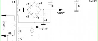
For anode power supply of the phono preamplifier, a transformer with a midpoint on the secondary winding is used, which allows you to obtain two voltages - 175V and 350 V.
Fig. 45.
Power transformer connection diagram
The stabilizer described in the article by E. Karpov “High-voltage stabilizer with a low ripple level” was used as voltage stabilizers.
Rice. 46.
Stabilizer circuit 150V
Rice.
47. 300V stabilizer circuit
Rice. 48.
Appearance of the 150V stabilizer module
In the topic Simple high-voltage stabilizer, the author provides a link to the electronic model of this stabilizer for the MicroCap simulator. The article “High Voltage Low Ripple Regulator” provides recommendations for changing circuit ratings for the required output voltage. The filament stabilizer is made according to the scheme of the author US5MSQ.
In my case, the transformer voltage is 2×8 V. A 5v1 zener diode is used, a 100 kOm variable resistor allows you to change the output voltage within a few tenths of a volt, the adjustment range depends on the input voltage.
If a transistor other than the IRF510 is used, it may be necessary to change the value of resistor R2 or use a zener diode for a different voltage. The power source for incandescent lamps does not have a galvanic connection with a common ground.
Rice. 49.
Filament stabilizer circuit
Fig.
50. Appearance of the filament stabilizer module
Smoothing the filament current ripples turned out to be insufficient for this circuit. In order not to remake the transformer and filament stabilizer, a simple compensation scheme for combating the background was used. An artificial midpoint is created at the output of the stabilizer using two 30 Ohm resistors. This midpoint is connected to common ground by a 2x2.2 uF film capacitor.
↑ Delay in supply of filament voltage and anode voltage
Since the phono preamplifier uses direct coupling, it is very desirable to delay the supply of the anode voltage, and to extend the life of such expensive lamps today, also smoothly supply the filament voltage.
The design uses a delay timer by V. Timofeev, described in the magazine “Amateur Radio” No. 1 for 2013, pages No. 8-11. Rice. 51.
Delay timer in standard form
Fig.
52. Modification to suit my needs
May the author forgive me, but I made some changes. I changed the module’s power supply to 12 V, since my relay is not 27, but 12 V. To do this, I removed one electrolytic capacitor and installed a three-terminal stabilizer in its place. I increased the capacity of the second capacitor and placed it on its side, away from the stabilizer radiator. Film capacitors of 330 and 100 nF are soldered to the legs of the stabilizer on the reverse side of the board.
I also abandoned the two trip relays and powered the delay unit from the filament windings, rather than from a separate transformer. I always place protective resistors in parallel with the power filter capacitors. I did not turn them off while the device was operating and reduce the voltage on the relay windings after they were activated.
After assembling all the blocks into the case, it turned out that in order to reduce interference, it was necessary to remake the board with relays and powerful resistors and change the location of the filament stabilizer board.
It turned out to be convenient to observe changes in noise and interference on the circuit in the Realtime Analyzer
. You can quickly move modules, change the location of the transformer, while observing changes in the readings of the device’s own noise. As a result, the relay for switching the anode circuits with resistors had to be placed on a separate board to the power filter, the smooth filament supply relay with resistors, the delay module blocking relay, the filament midpoint resistors and the non-polar capacitor were left on the board installed above the delay block. The delay unit swapped places with the filament stabilizer. The network cable is placed in an additional screen.
↑ Corrector housing
I did the same with the body as last time. I looked on the Internet and bought it. The requirements for the case were not strict, it had to be no more than a certain size in order for all the equipment to fit on my “audiophile” chest of drawers, accommodate all the modules, and have an acceptable appearance. As a result, I received the proud inscription “Dun Mei Audio” on the front and rear panels.
Ventilation holes are provided only in the top cover. All boards, transformers and capacitors will be attached to the bottom, plus the ventilation holes had to be drilled a little. And then, when rearranging, drill a little more.
The phono stage boards and power supply are housed in one housing. The inputs of the boards are connected to the input connectors by shielded wires, the low-current ground is connected to the common ground at the grid of the first lamp, the input and output connectors are isolated from the case. To dampen the phono stage boards, I used rubber shock absorbers from old CD-ROMs; the rest of the boards were placed on regular stands. Next to the phono stage boards there is an output stage with two transformers. The power supply is separated by a steel screen. Next come anode supply stabilizers, a delay unit and a filament stabilizer.
Above the block for delaying the supply of anode voltage and filament on the second floor, relays and powerful resistors are located. The anode supply diode bridge is mounted under the transformer casing. The power filter capacitors are mounted next to the stabilizers. In both cases, a CRC filter is used.
The common ground is the minuses of the first capacitors (47 uF), connected by 1.5 mm tinned wire; all ground wires of the device come here. The transformer is toroidal, attached to the housing through a vibration-isolating rubber gasket, covered with a steel casing; ventilation holes are made in the upper wall and in the casing wall facing the front panel.
Homemade phono stage
The device is very minimalistic, on its front panel there are two input tulips, a switch for separating the common wire from the ground and a three-pin output jack:
Everything inside is also quite simple. Bipolar power supply:
And the phono stage itself:
Zoran.Velinov made the boards with LUT as follows: printing on glossy paper, transferring to heated foil by rolling on top with a stainless steel pipe, etching with a composition of 12% peroxide and 15-20% hydrochloric acid, the rest is water.
Boards after assembly:
For some reason, the master decided to solder the terminal blocks into the boards only for the duration of the test, and then unsolder them and solder all the wires directly into the boards. A matter of taste.
The master disassembles a computer power supply:
Flips over the power connector:
Places stickers on the body:
Places its boards inside (an insulating gasket between the case and the printed circuit conductors is required), connects them to power, connects the input cables:
Connects the power connector via a switch to the power supply board (CAUTION! You should also add a fuse here):
Connects input tulips:
Switch for separating the common wire and grounding:
On the back side:
Connects the three-pin output jack:
Isolates it from the reverse side like this:
Well, now you can connect everything and listen:
If you are interested in this phono stage, download all the files necessary for its manufacture in one archive.
Source
↑ Parameters of my assembled phono stage
With the same gain of the channels (2% difference), the noise in the left channel is 2 dB higher than in the right.
The noise level parameters below correspond to the left channel. Gain (1kHz) 210 Input impedance 47 kΩ Total harmonic distortion (1kHz, Uout=0.75V) 0.04% Unweighted noise level - 63 dB Type C weighted - 66 dB Type A weighted - 78 dB Output impedance - 560Ω Characteristic deviation from standard RIAA (20Hz - 20 kHz) - 0.5 dB Power consumption - 70 W Set-up time 38.5 sec Dimensions 230 x 390 x 90 mm Weight 6.9 kg
Rice.
53. THD phono stage
Rice.
54. Anti-RIAA phono stage
Rice. 55.
Phono stage's own noise
Rice. 56.
Own noise of the phono preamplifier by octaves
Rice. 57.
Phono stage self-noise (C-weighted)
Rice. 58.
Phono self-noise (A-weighted)
Vinyl corrector with bipolar power supply
The following circuit was found in the book “The Art of Circuit Design” - P. Horowitz, W. Hill (p. 167). The diagram shows one channel of the vinyl corrector:
Essentially this is the same scheme. But now bipolar power supply is already used, and the ratings of the frequency-setting circuits are calculated differently. The use of bipolar power allows you to abandon both the use of dividers to form half the supply voltage and the output capacitor. The input capacitor should be left to cut off possible DC voltage from the previous stage, as well as an element of the input RC circuit.
The graph represents the frequency response of the playback amplifier plotted relative to a gain value of 0 dB at a frequency of 1 kHz.
TL062, TL072 can also be used as operational amplifiers, but it is better to give preference to TDA2320, L4558, LM833 and other op-amps intended for audio circuits, or those with high input impedance (>1MOhm), low noise level and high signal slew rate.
↑ Results
I am completely satisfied with the sound of the new phono stage.
No, I expressed it incorrectly. The music that I hear with the help of the new phono preamplifier completely suits me. If time permits, I can listen for hours and still get great pleasure. I think that there won’t be a third article about the phono stage for a long time. Among the shortcomings of the new phono stage, I can note its high power consumption and, as a result, decent heat generation, the presence of an output transformer stage, which somewhat complicates and makes the design heavier and the need to select lamps for the first stage.
Thank you for your attention and patience!
Further there will be only links to audio files and projects of individual phono stage modules for the EAGLE CAD program, including the John Broskie TubeCad Journal phono stage board project. If there are people who want to repeat a particular module or even the entire project, they will be able to use the parts they have, rather than looking for what I had. If necessary, you can change the arrangement of parts or the dimensions of the board for optimal layout, etc. Happy creativity everyone!
↑ Literature and sources mentioned
1. “Tube Phono Preamps Several topologies & tricks Part 1 of 2” www.tubecad.com Copyright © 2001 GlassWare 2. V. B. Grigorov “Reducing the noise level in low-frequency amplifiers.” Mass radio library 1956 3. E. Babichenko, I. Gaponov. “RIAA Amplifiers – Vacuum Triode Corrections for “High-Speed” (Electrodynamic) Pickups.” 4. E. Karpov “SPECTRA - II”. 5. Lecture No. 13. Current sources on bipolar and field-effect transistors. Stabilizers. 6. M. Jones “Tube amplifiers” DMK Moscow 2007 7. E. Karpov “High-voltage stabilizer with a low ripple level.”
Vinyl corrector, proven simple schemes
A vinyl corrector is an essential component of any vinyl disc player. The quality of playback directly depends on its quality. Today we will consider proven and repeatedly tested schemes according to which you can assemble a vinyl corrector.
I have already told you what RIAA correction is and why it is needed . Today we’ll look at a couple of op-amp-based vinyl corrector circuits. Both circuits were assembled and tested personally, and have been working perfectly for more than 5 years.
↑ After what was written
The operation of the phono stage revealed my mistakes.
I had to improve ventilation using additional holes in the top cover. Now it looks like this. PPS A person is driven by curiosity, and discussions about the difference in sound (advantages over 6N23P and 6N23P-EV) of 6DJ8, 6922, ECC88, E88CC, etc. lamps from different manufacturers only fuel it, this is curiosity itself. Since I had not yet earned money for new 6DJ8s, I bought myself a pair of used 6DJ8 lamps from Matsushita on Japanese Yahoo.
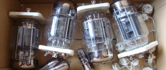
6DJ8 lamps
The seller reported that the lamps were checked for serviceability. Considering that a pair was being sold, there were timid hopes that the lamps would have similar parameters. I received it, installed it in the phono stage and started listening. The lamps fit within the passport specifications, with Ua = 100 V, Ug = - 1.95 V, Ia = 10 mA for the first and 12 mA for the second. But with increased internal noise, they apparently did a good job and therefore retired. I have several similar used 6N23P lamps, with very close halves, which are also noisy.
In the left channel the first lamp is 6DJ8, in the right 6N23P-EV
When installing the first tube, the self-noise in the left channel increased by 10 dB, and the gain decreased by 3 dB. Given this circumstance, I did not carry out other measurements.
One of the lamps with very close halves, the second one has a larger spread, is not very suitable for the first stage of my product. I started listening to music, “closing my eyes” to the noise. I listened, I listened honestly. Maybe there is something wrong with my ears or the system does not have the proper level of resolution? But “I got the impression” (it seemed) that the sound is more influenced by the operating modes of the lamp, the organization of bias and the circuit design of the first stage than by the manufacturer of the lamp itself.
Used lamps are the wrong solution; they can be used at the first stage to check the functionality of the project. In the future, it is better to buy new lamps and select suitable ones from them. I returned the 6N23P-EV back. I decided to postpone the experiment until the moment when the money simply has nowhere to go, but for now I’ll just listen to music.
↑ Idea
The desire to make a tube preamplifier-phono preamplifier has been brewing for a long time. In the garage there was a record player “Electronics” 060, forgotten by everyone and in need of repair, donated as a useless gift by a workmate. There was a stack of CDs languishing, which I started buying as a student, in the hope that someday I would buy myself a player. And finally, the desire turned into a decision. Everything is decided, I will do it. The agony of choice began. Which scheme to choose, which layout to prefer? Should I make a full preamplifier or a phono preamplifier? Reading articles on the Internet and smart books only added doubts; there was no experience in manufacturing such devices. In order to somehow organize the thoughts swarming in my head, I drew up a kind of technical assignment for myself.
- An easy-to-implement scheme.
- Preamp parts available to me.
- The output signal level is 1 Volt (the nominal sensitivity of my ULF).
- Low output impedance.
- Possibility to connect a cassette recorder with an output signal level of 0.5 Volts to the amplifier.
- The housing must match the design of my bass amplifier.
For the project, we purchased a housing, a power transformer and RCA connectors. I had all the other parts, either new or used.